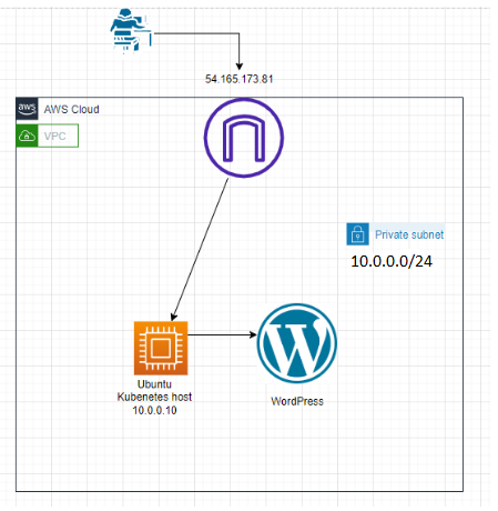
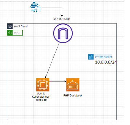
I have used the following link to deploy the PHP Guestbook application with Redis (https://kubernetes.io/docs/tutorials/stateless-application/guestbook/)
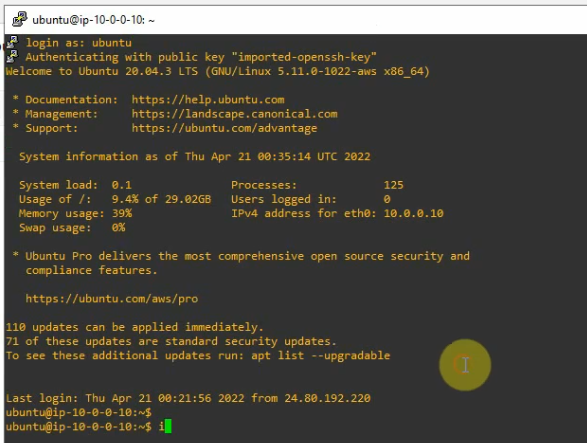
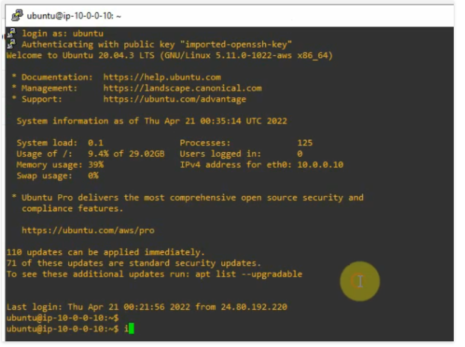
Set up an Ubuntu Linux with 2GB RAM and 30GB storage for the Kubernetes host. Allow SSH and HTTP from anywhere to the Linux instance on Security Group.
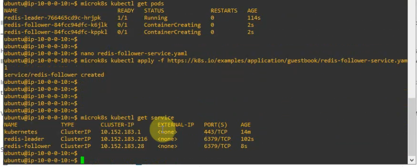
#nano redis-follower-service.yaml
# SOURCE: https://cloud.google.com/kubernetes-engine/docs/tutorials/guestbook
apiVersion: v1
kind: Service
metadata:
  name: redis-follower
  labels:
    app: redis
    role: follower
    tier: backend
spec:
  ports:
    # the port that this service should serve on
  - port: 6379
  selector:
    app: redis
    role: follower
    tier: backend
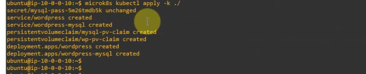
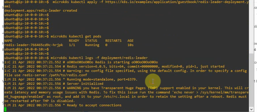
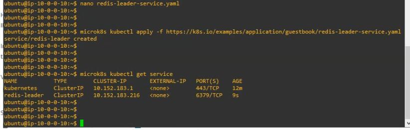
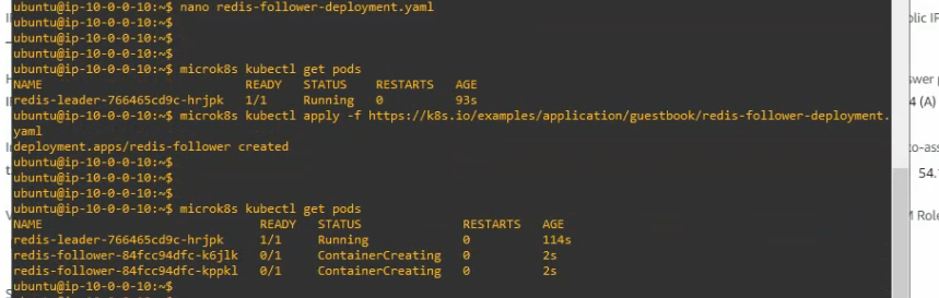
#Apply the Redis Service with the deployment file.
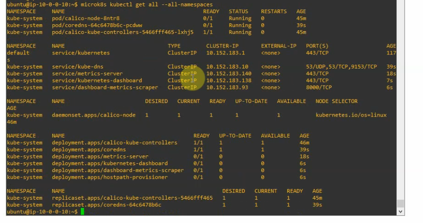
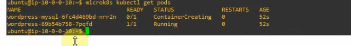
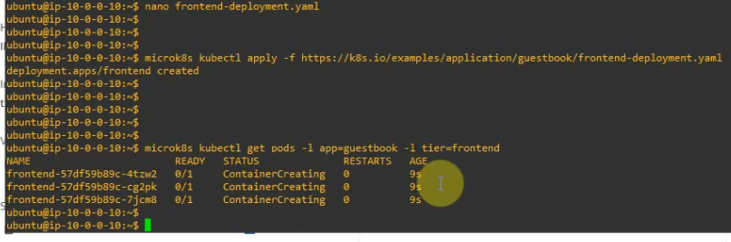
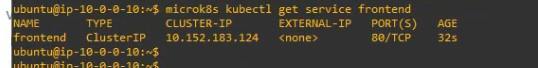
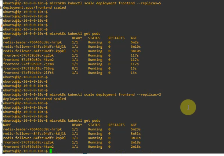
microk8s kubectl get pods -l app=guestbook -l tier=frontend
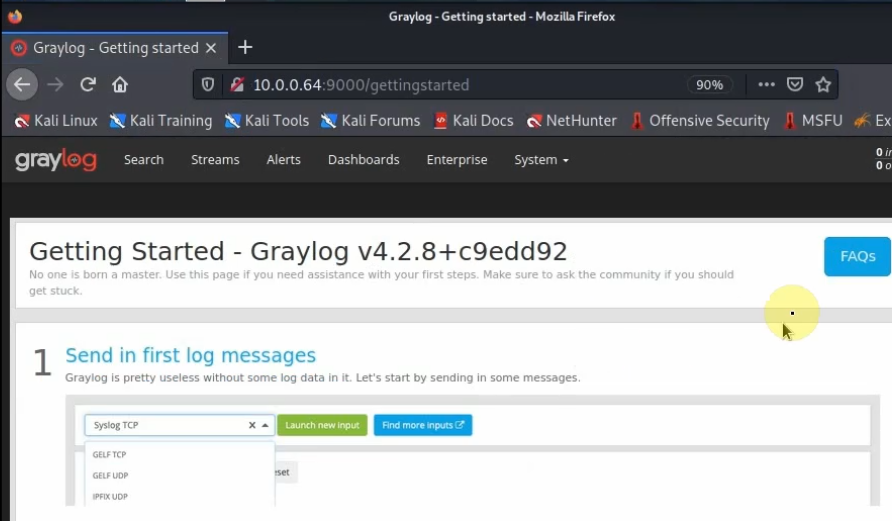
+ Creating the Frontend Service.
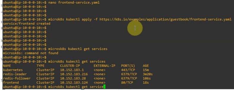
#nano frontend-service.yaml
# SOURCE: https://cloud.google.com/kubernetes-engine/docs/tutorials/guestbook
apiVersion: v1
kind: Service
metadata:
  name: frontend
  labels:
    app: guestbook
    tier: frontend
spec:
  # if your cluster supports it, uncomment the following to automatically create
  # an external load-balanced IP for the frontend service.
  # type: LoadBalancer
  #type: LoadBalancer
  ports:
    # the port that this service should serve on
  - port: 80
  selector:
    app: guestbook
    tier: frontend
#Apply the frontend Service with the deployment file.
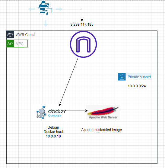
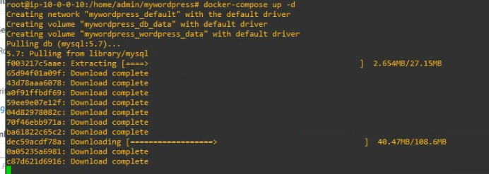
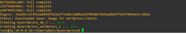
I have explained how to build a customized Docker image using Docker compose on-prem (https://tungle.ca/?p=2486). In this post, I will build a customized Docker image using Docker compose on AWS, then deploy WordPress via this docker container.
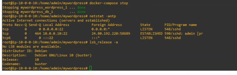
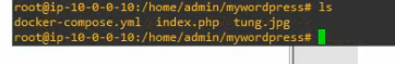
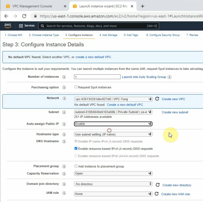
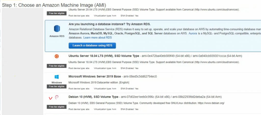
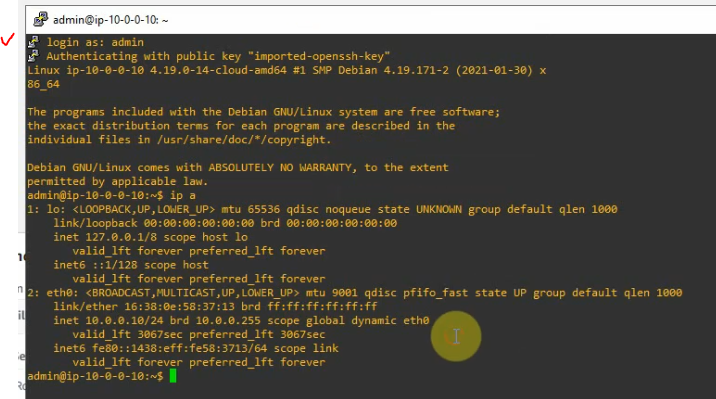
+ Create a new Debian Linux instance on AWS. Then, SSH to the instance and check Debian’s host version.
lsb_release -a
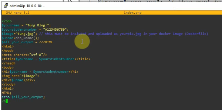
+ Create an index.php file with your customized information.
nano index.php
<?php
$yourname = "Tung Blog!";
$yourstudentnumber = "A123456789";
$image="tung.jpg"; // this must be included and uploaded as yourpic.jpg in your docker image (Dockerfile)
$uname=php_uname();
$all_your_output = <<<HTML
<html>
<head>
<meta charset="utf-8"/>
<title>$yourname - $yourstudentnumber</title>
</head>
<body>
<h1>$yourname - $yourstudentnumber</h1>
<img src="/$image">
<div>$uname</div>
</body>
<html>
HTML;
echo $all_your_output;
?>
Download a free .jpg image from the Internet and change it to tung.jpg
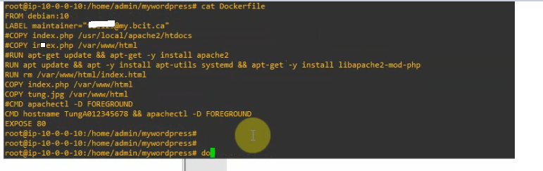
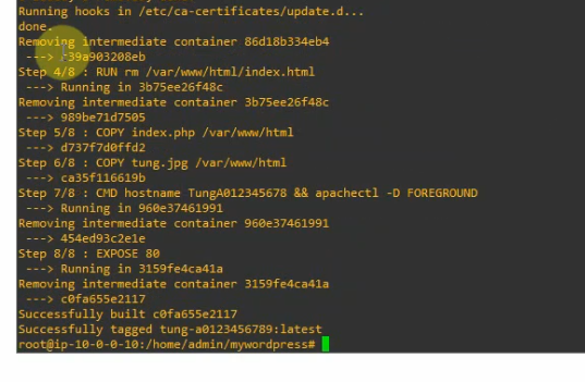
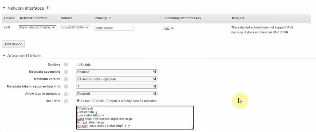
Create your sample docker file.
This tells Docker to: – Build an image starting with the Debian 10 image. – Label the container with your email address. – Install Apache web service and PHP module. – Remove the default index.html on the Apache web server document root directory. – Copy a new index.php file and your customized image to the Apache document root directory on the docker container. – Run the command hostname and apachectl -DFOREGROUND runs in the foreground. – Image to describe that the container is listening on port 80.
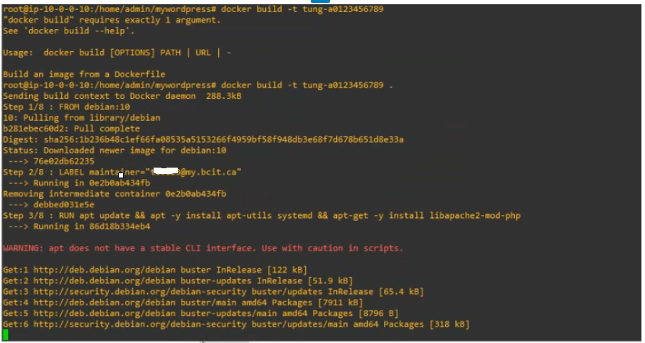
docker run -d -p 80:80 --cap-add sys_admin -dit tung-a0123456789
---
-- -d starts docker in daemon mode, in the foreground.
-- -d p 80:80 listening the port 80 on docker container
-- -cap-add sys_admin: basically root access to the host.
-- -dit: it is used for getting access to terminal inside a docker container. In this example is tung-a0123456789.
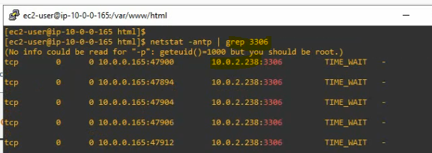
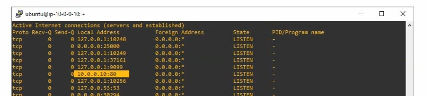
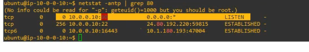
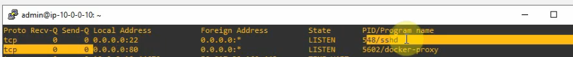
Check that port 80 is running on the docker container.
netstat -antp | grep 80
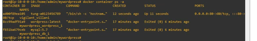
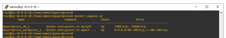
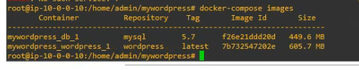
+ Check your application is running on a Docker container.
docker container ps -a
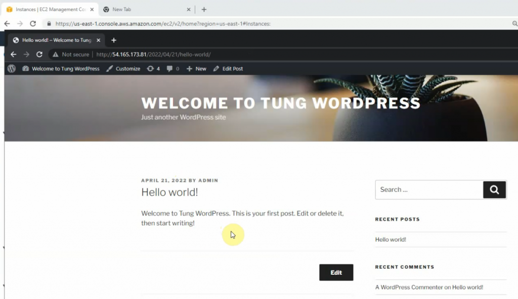
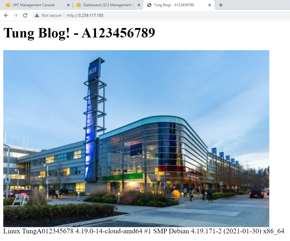
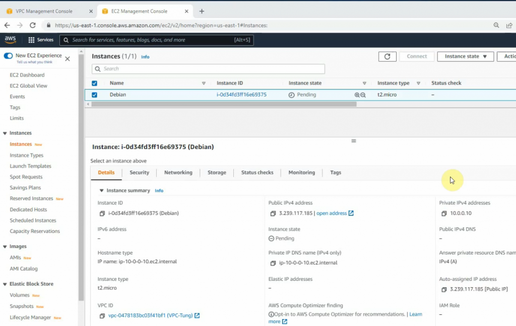
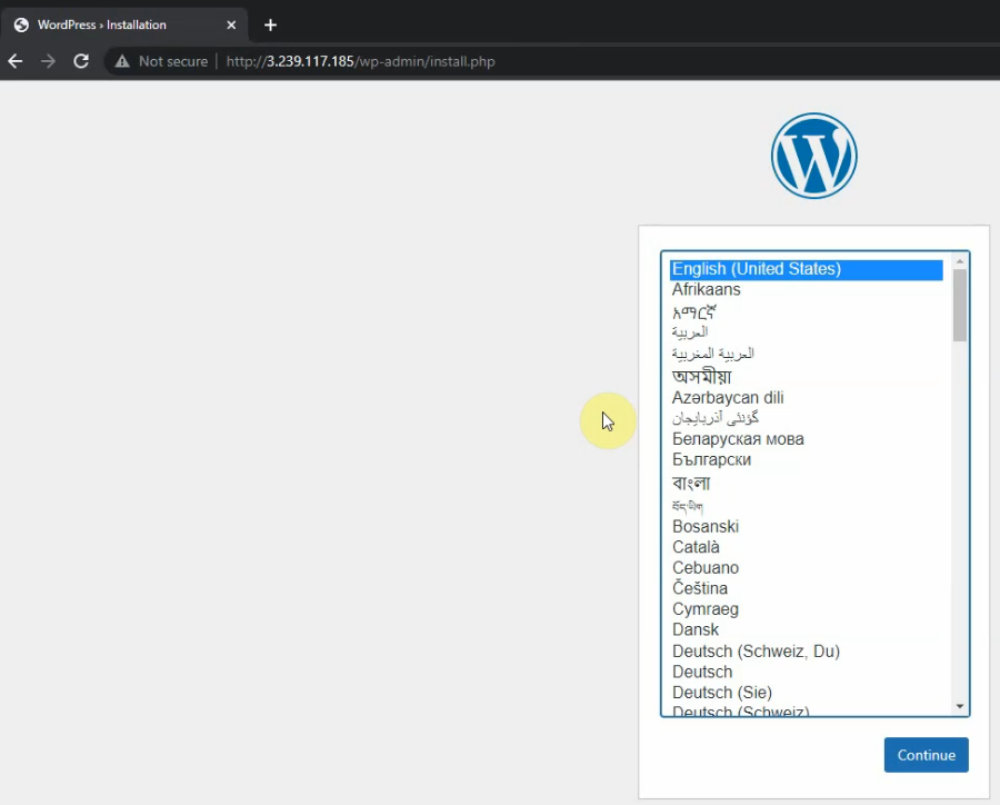
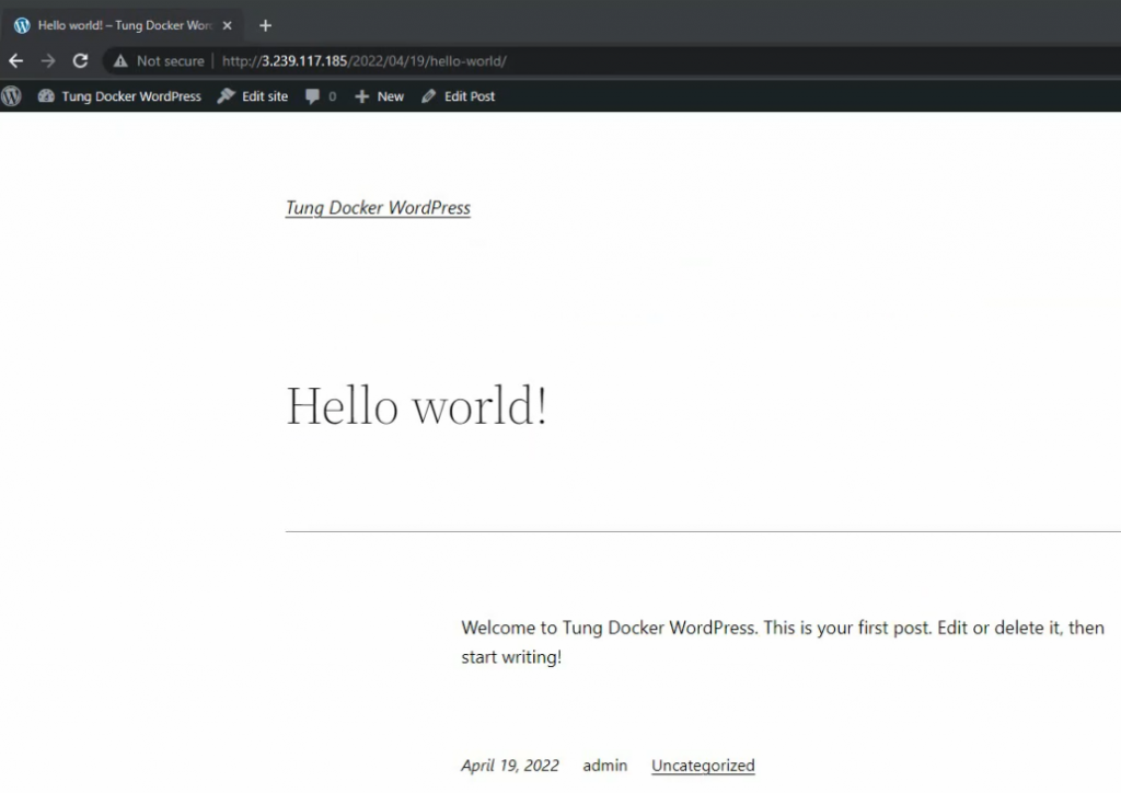
Connect to the Apache website with the PHP module on the docker container (http://3.239.117.185)
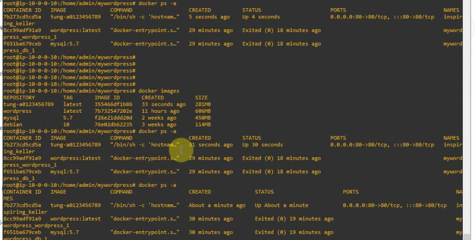
A few commands to use for checking the docker container.
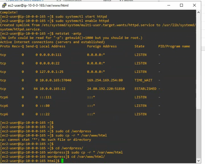
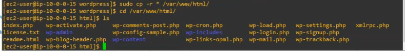
Copy all files on WordPress directory to /var/www/html
cd /wordpress
sudo cp -r * /var/www/html
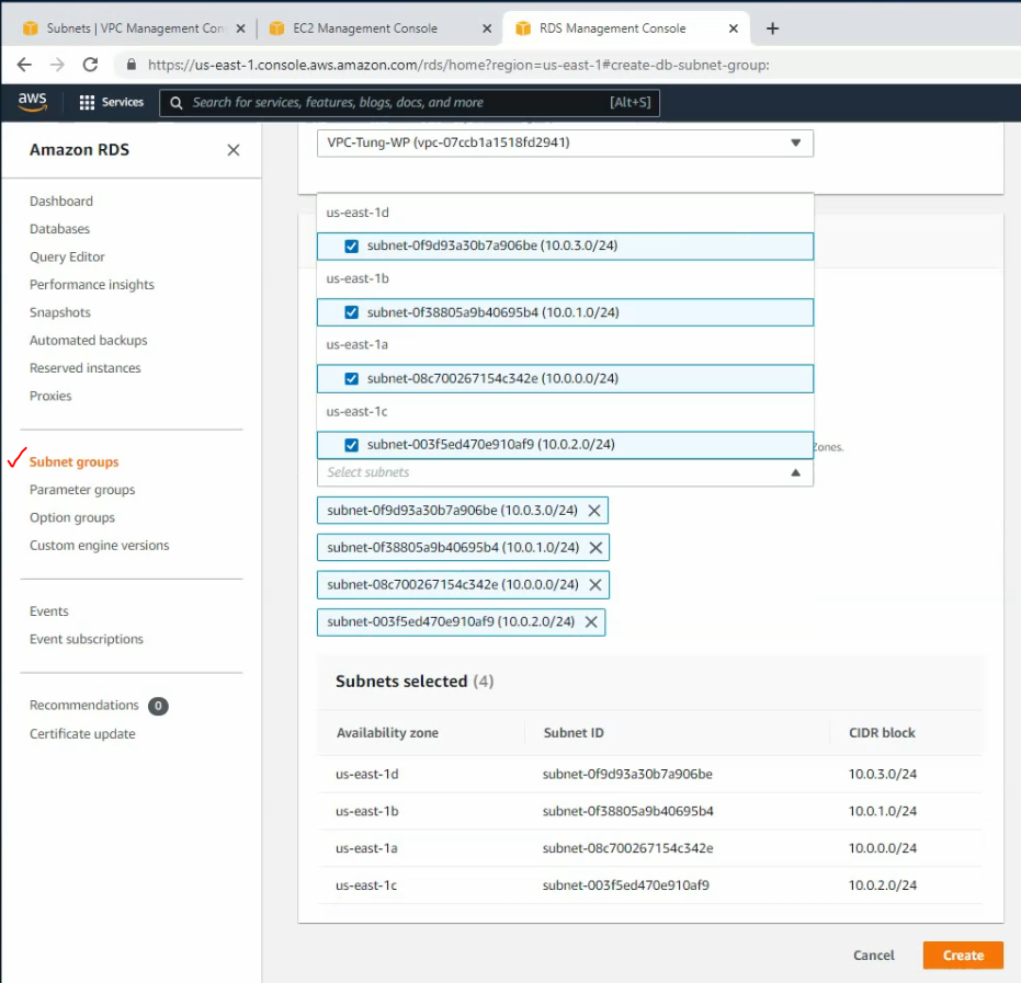
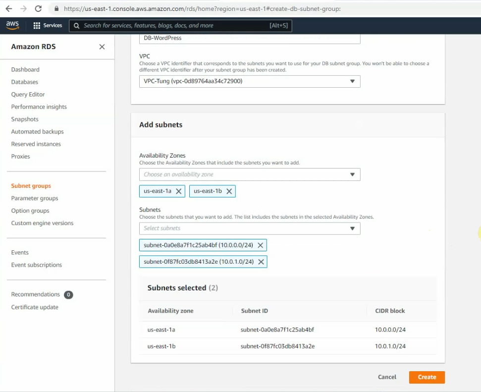
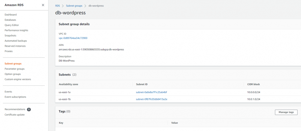
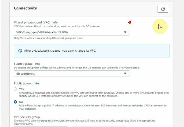
Go to Amazon RDS, create subnet groups on Amazon RDS.
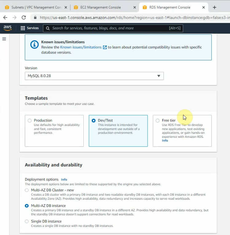
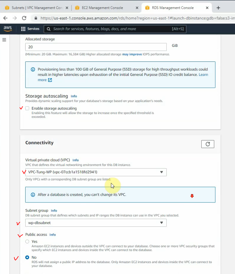
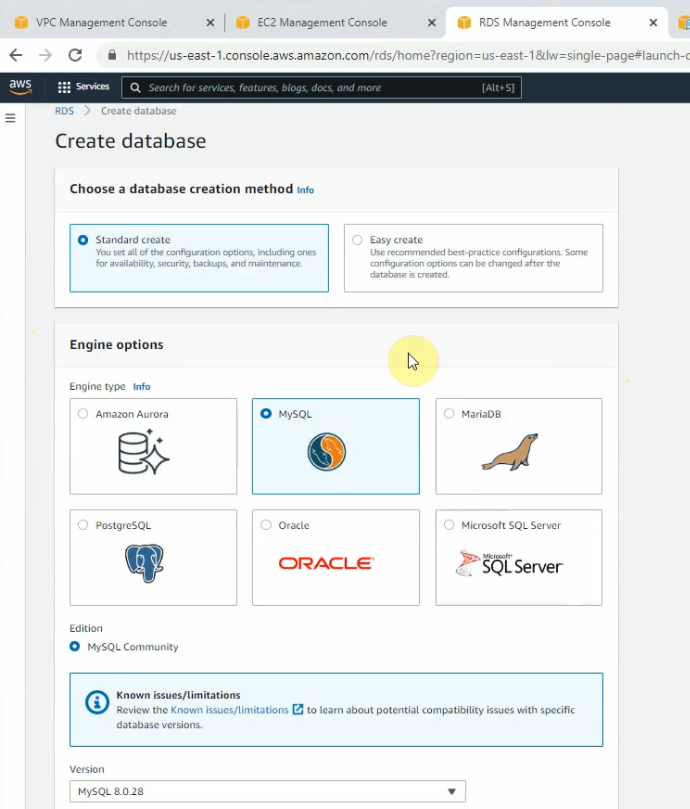
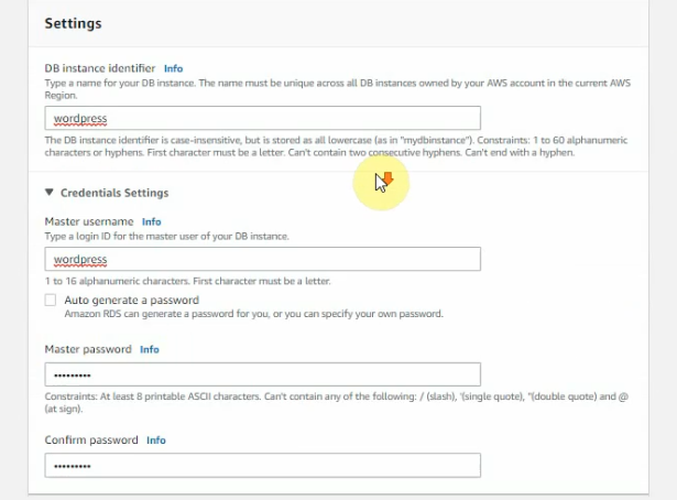
Create a new Database instance on AWS.
Choose the Free tier.
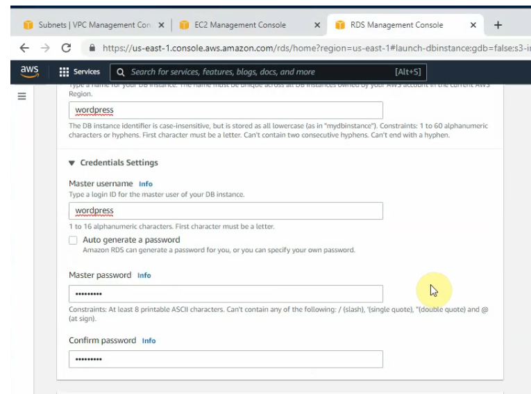
Enter wordpress on “DB instance identifier”, “master user name and password”
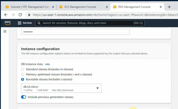
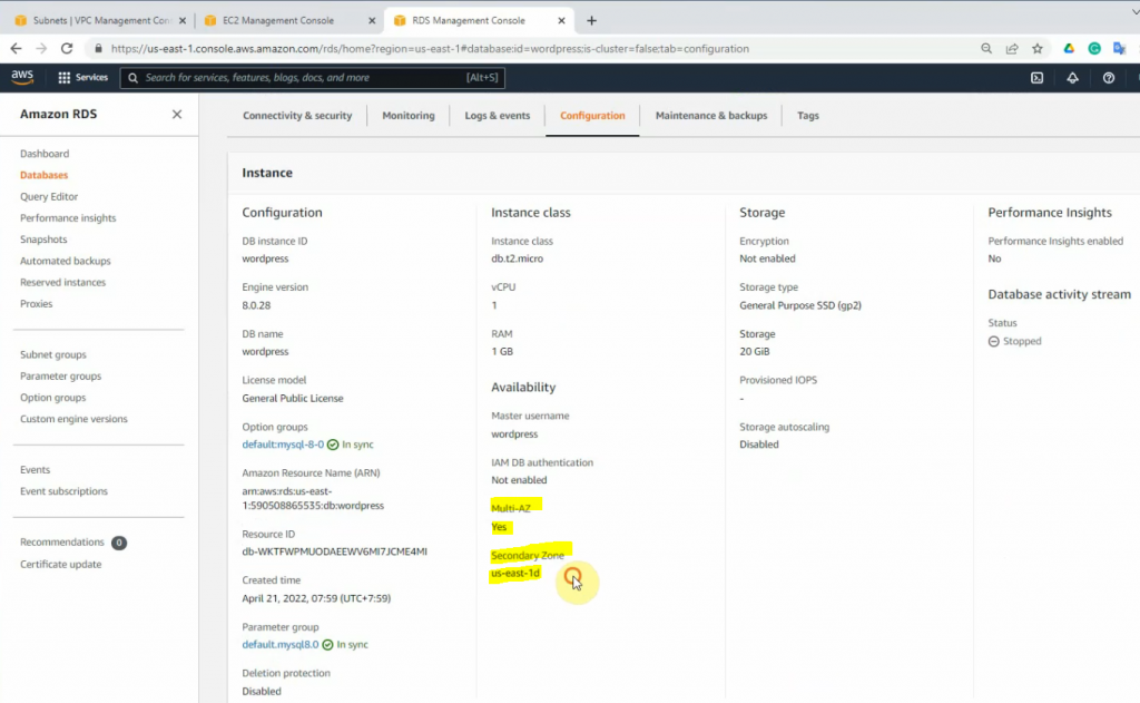
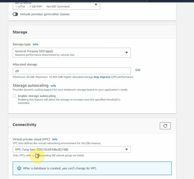
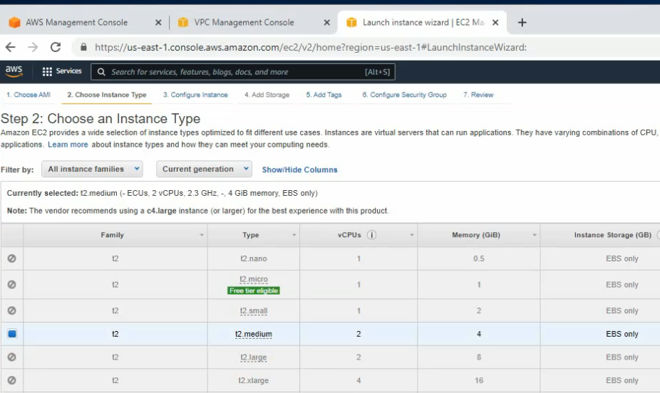
DB instance class is d2.t2.micro.
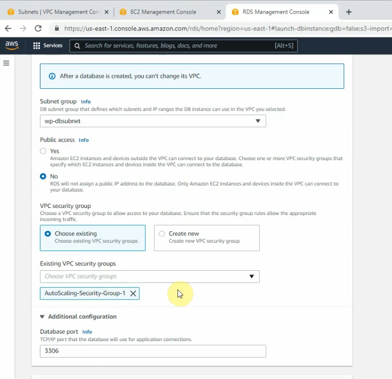
Public access is No.
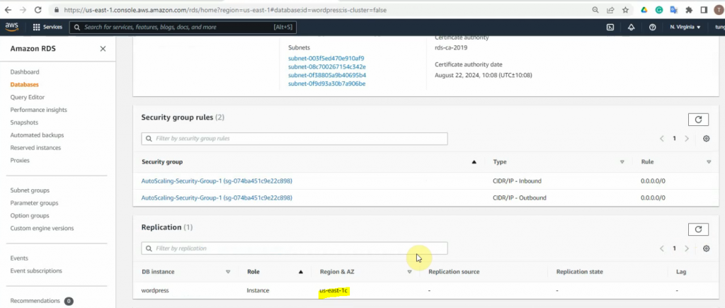
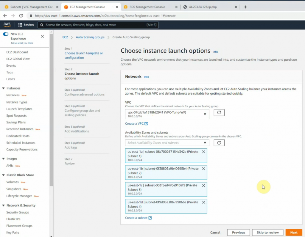
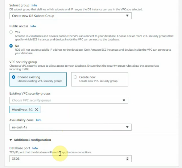
Choose the Availability zone as the following screenshot.
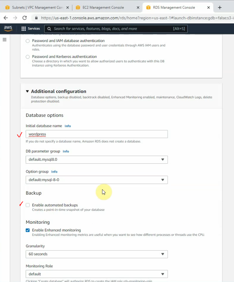
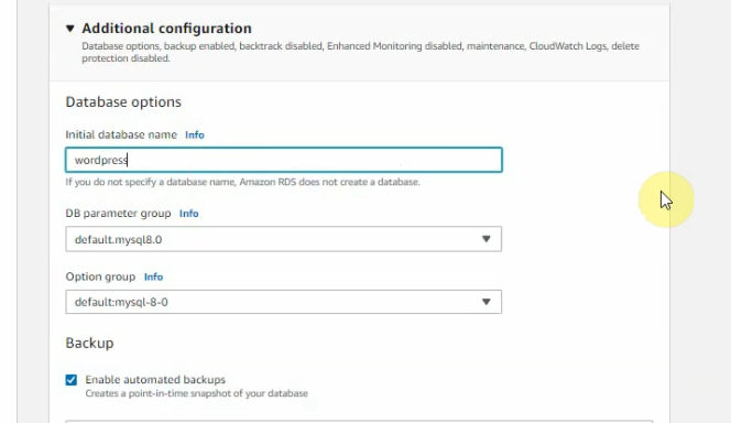
Enter “wordpress” on the initial database name.
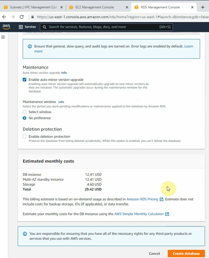
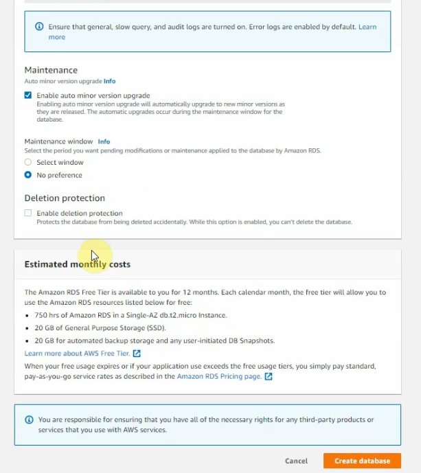
Backup retiontion period: 0, then click “Create database”.
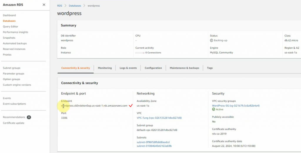
Wait a couple of minutes to completely create the database instance.
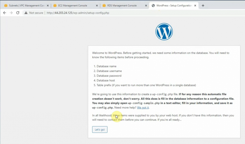
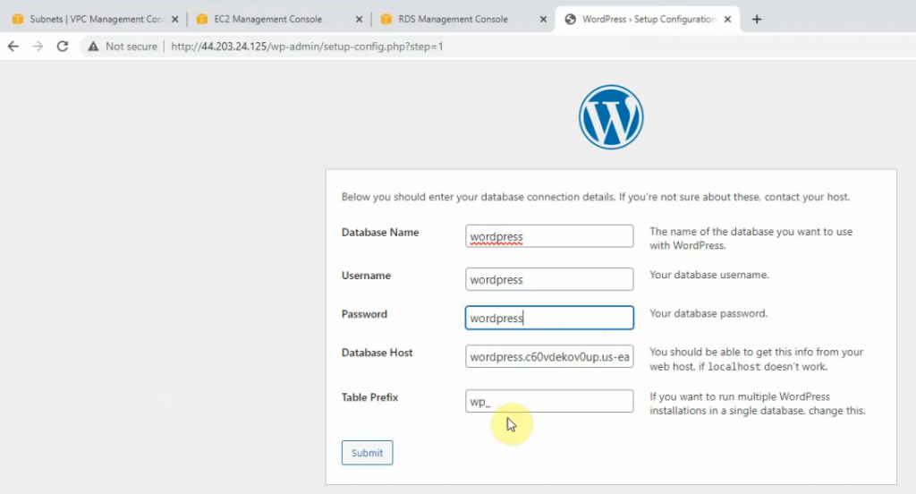
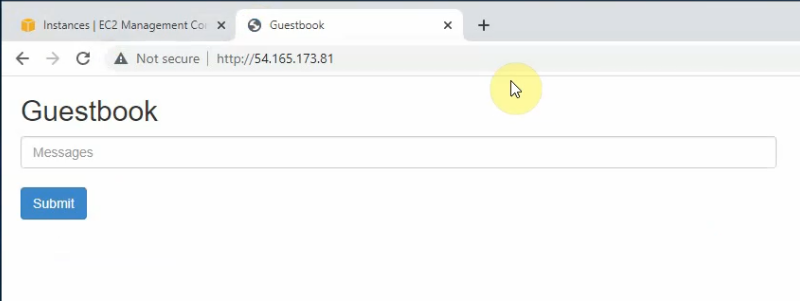
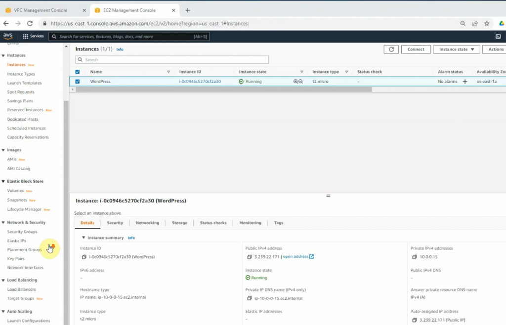
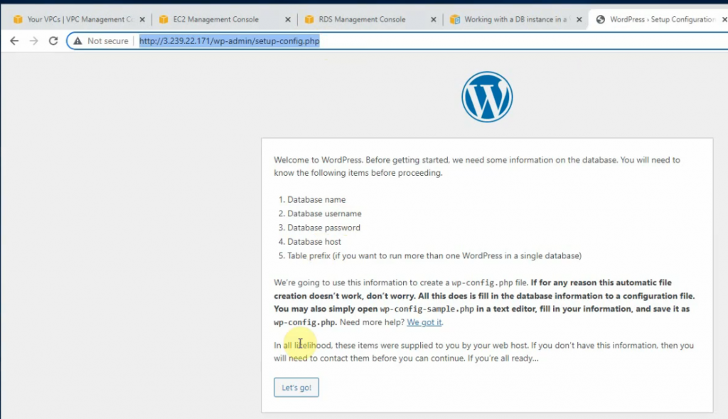
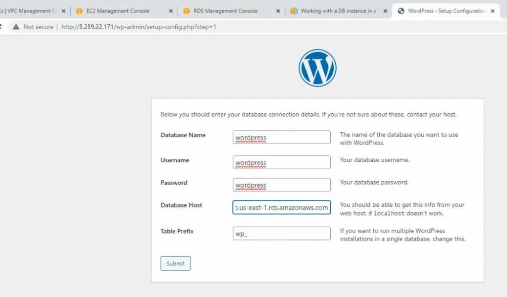
Access WordPress site via the public IP address of WP.
Database, username, password is wordpress.
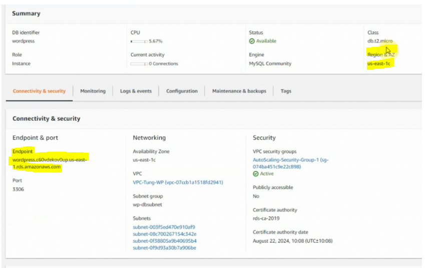
Database Host is the endpoint address of the RDS database on AWS on the previous screenshot.
Click Submit.
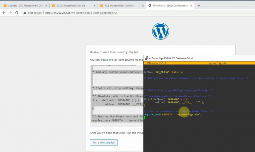
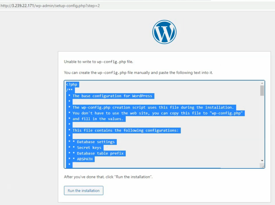
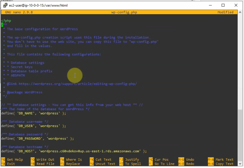
Copy entire content, open SSH shell on Linux instance. Create a new wp-config.php under /var/www/html.
sudo nano wp-config.php
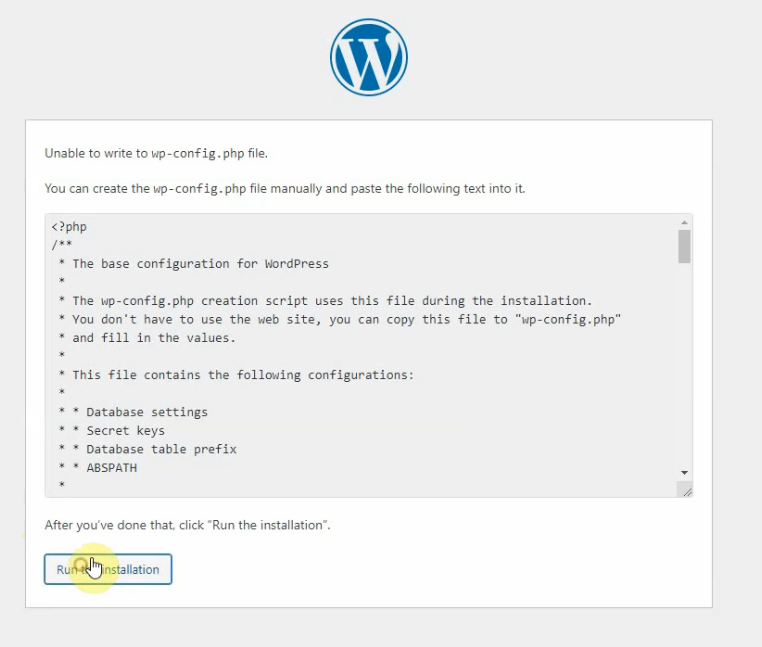
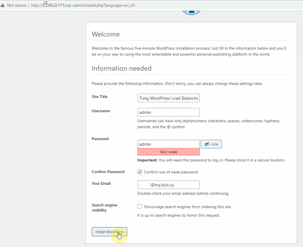
Back to WP web interface set up, click “Run the installation”.
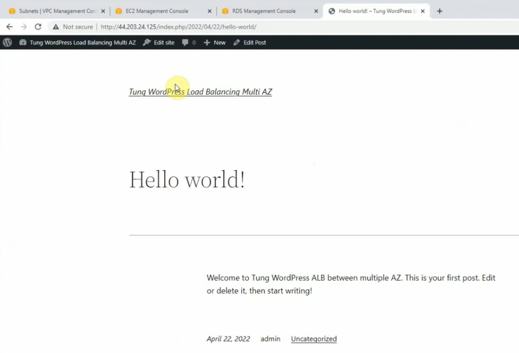
Click “Install WordPress”.
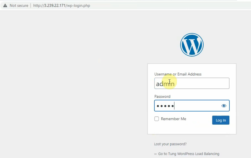
Log in WP.
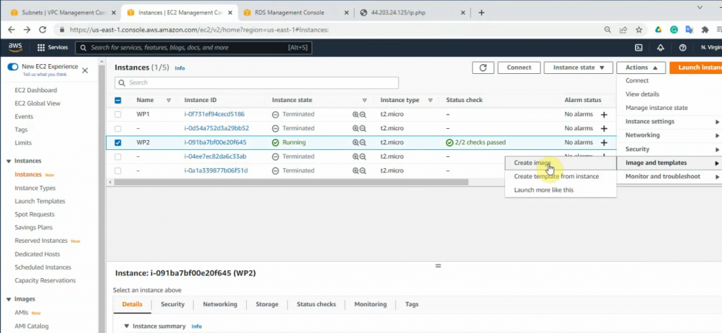
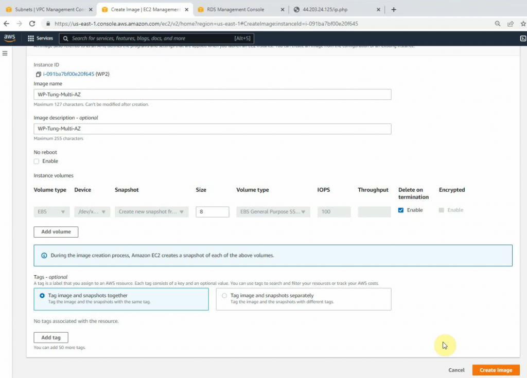
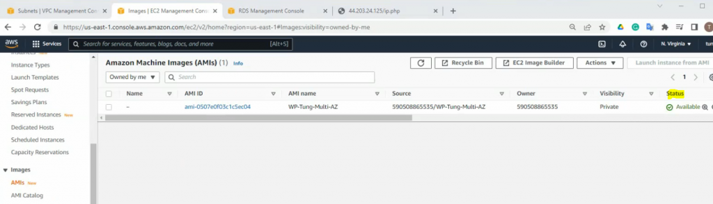
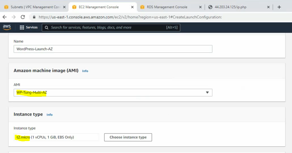
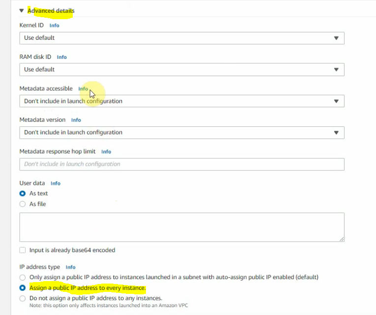
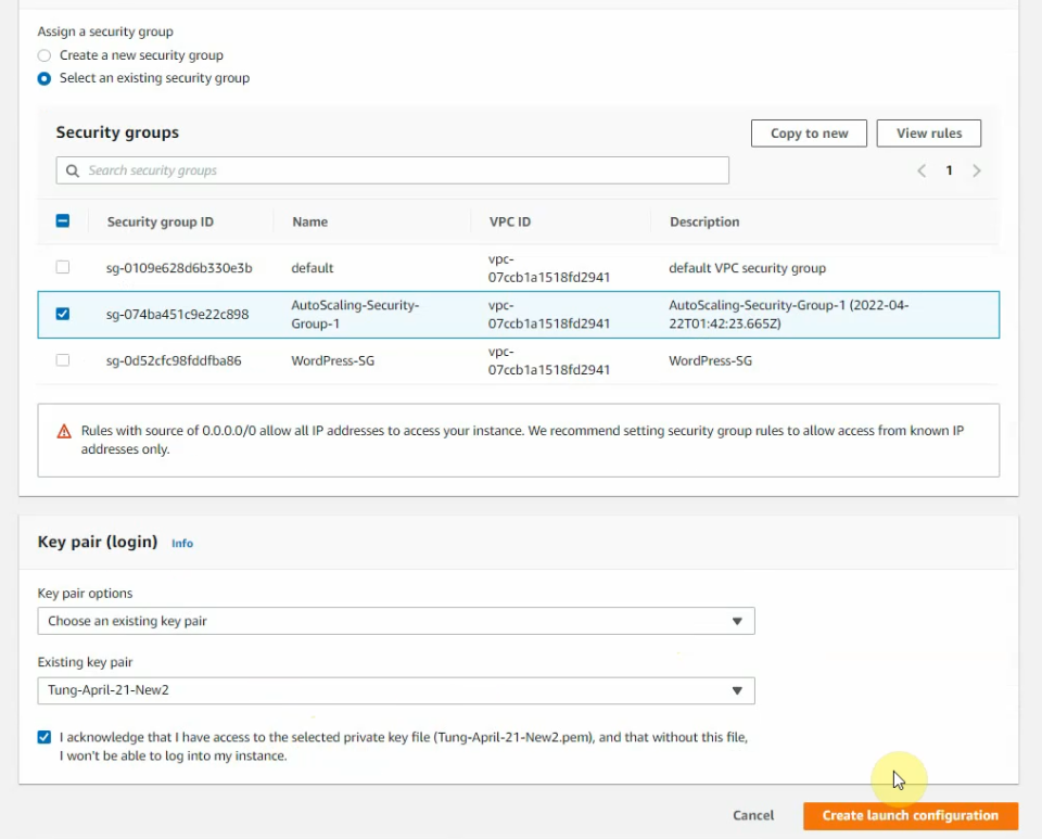
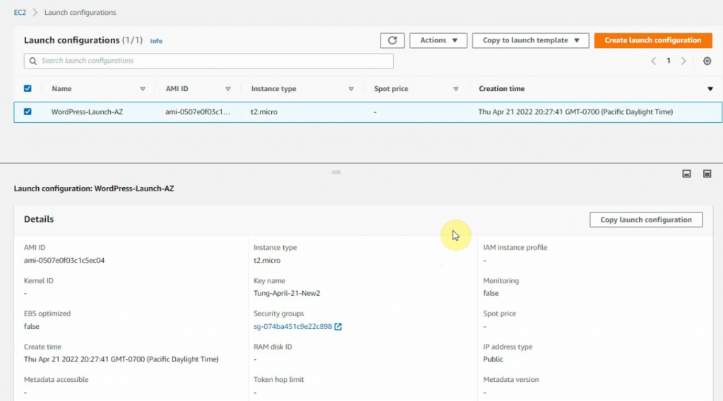
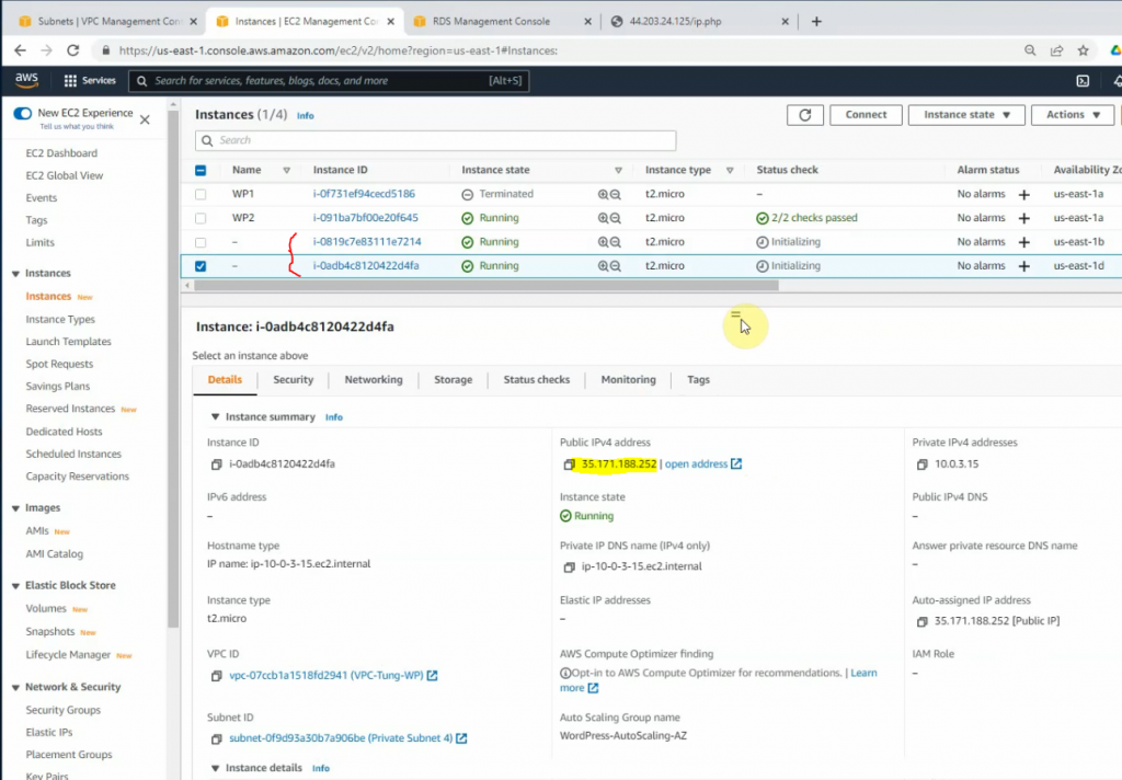
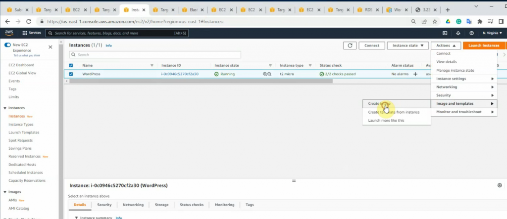
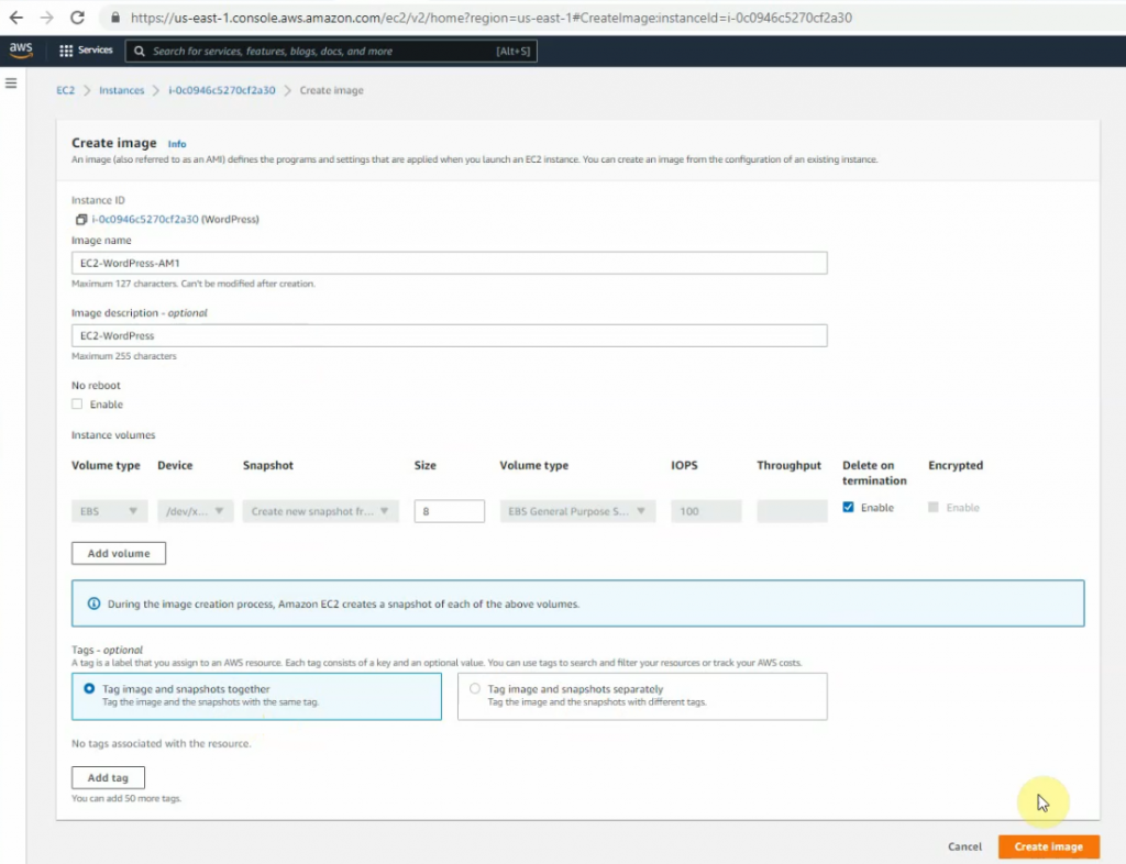
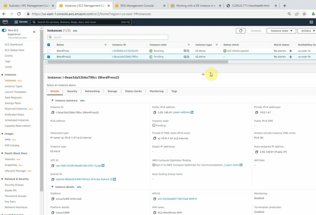
Now, create a new AMI image for this WP. Right-click the WP instance, on Actions – Image and templates – Create image.
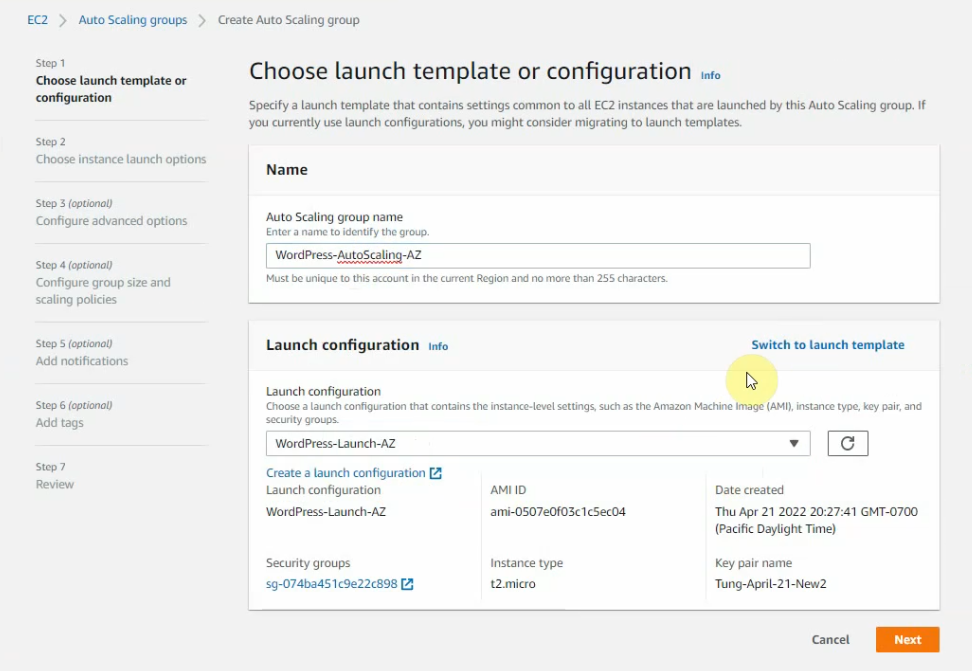
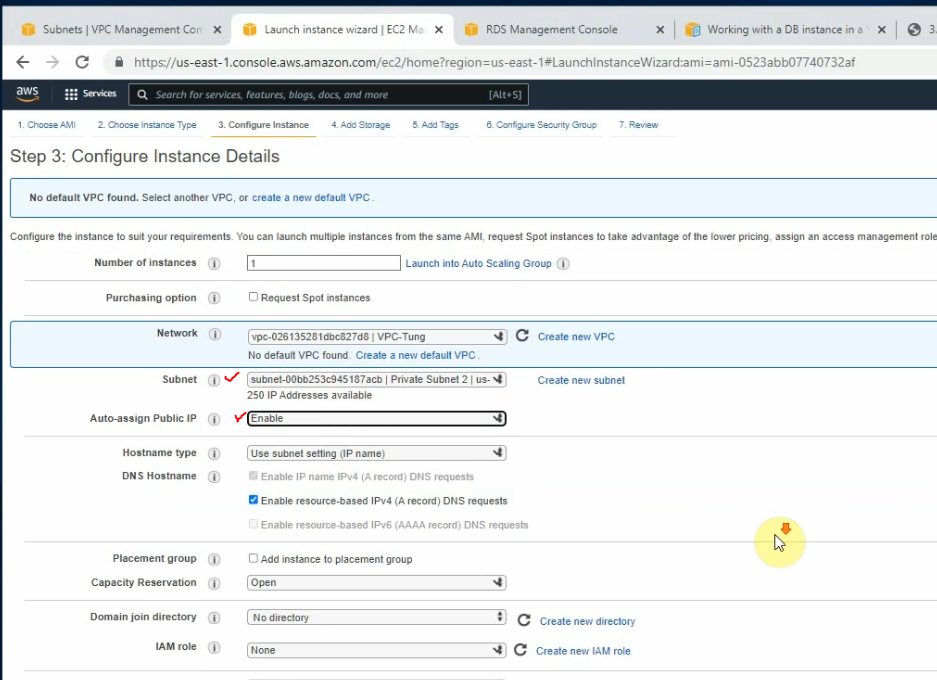
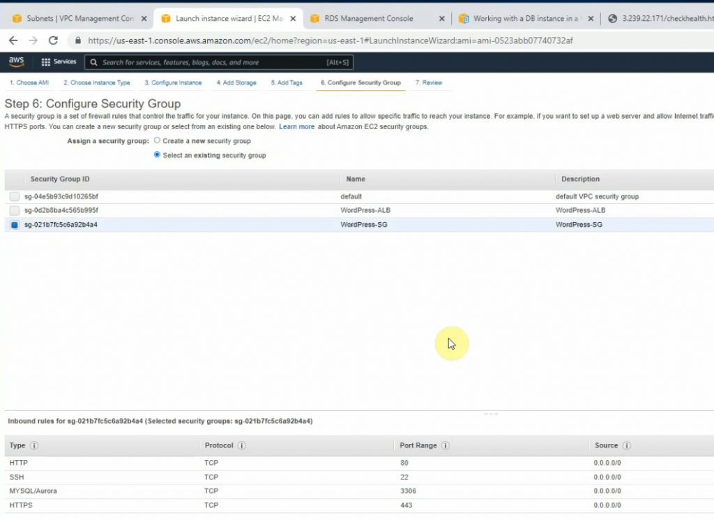
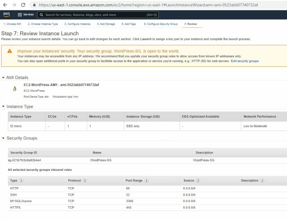
Right-click AMI. Click Actions – Launch an instance from AMI.
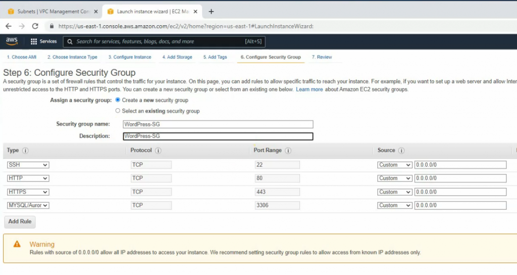
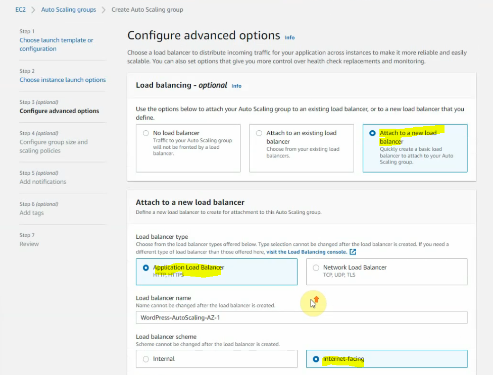
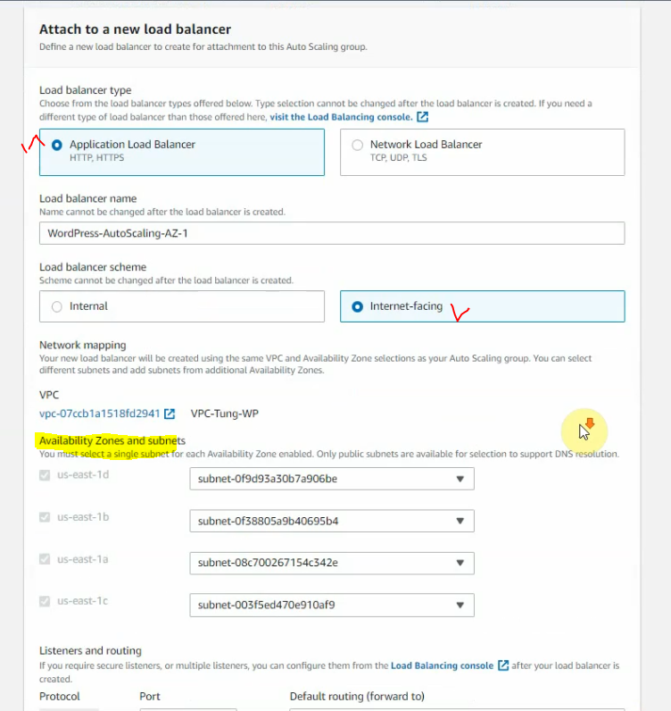
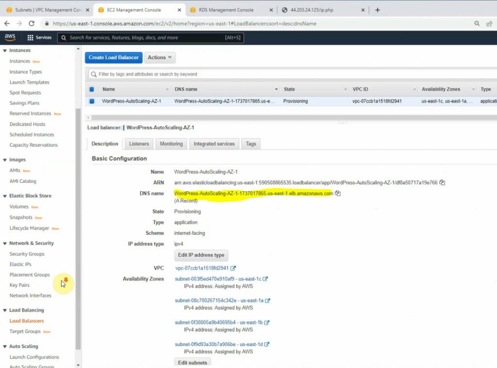
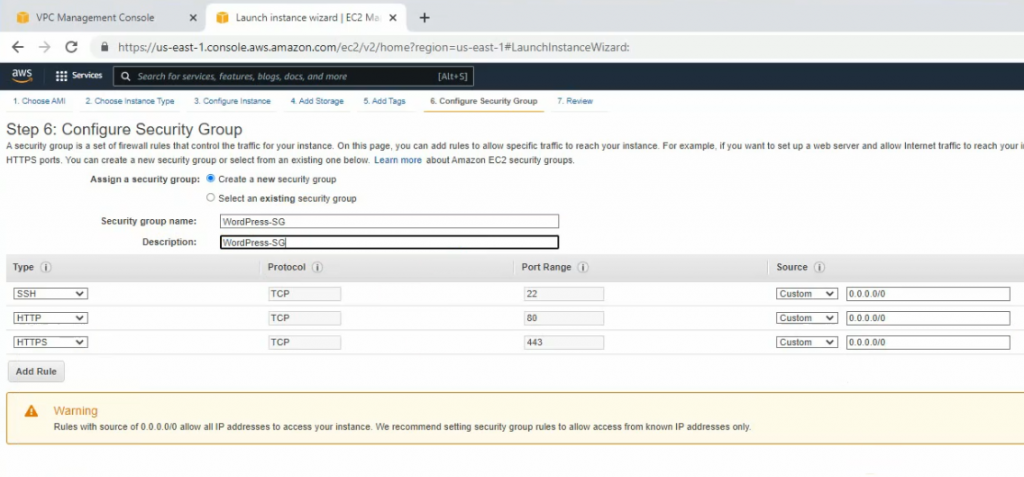
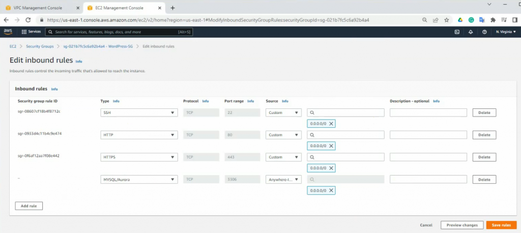
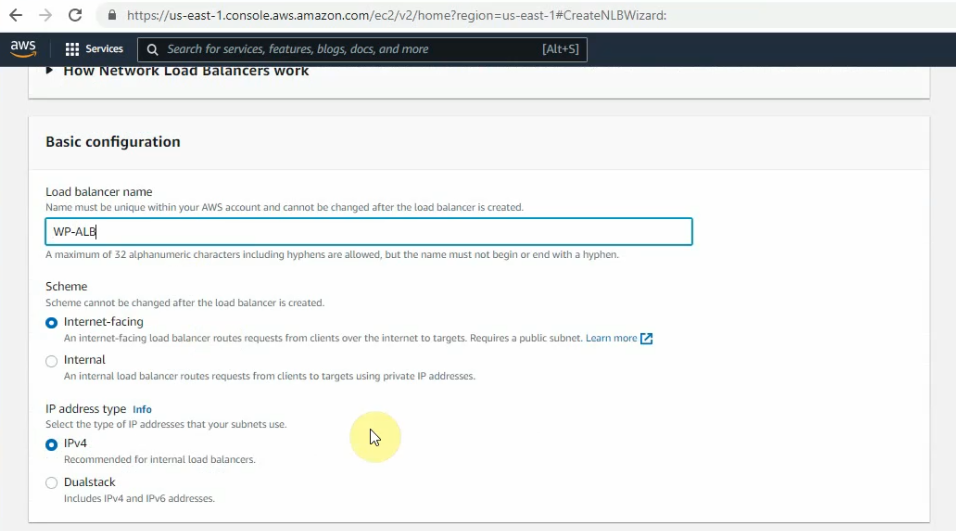
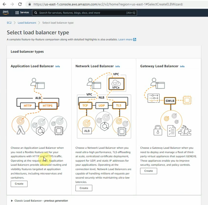
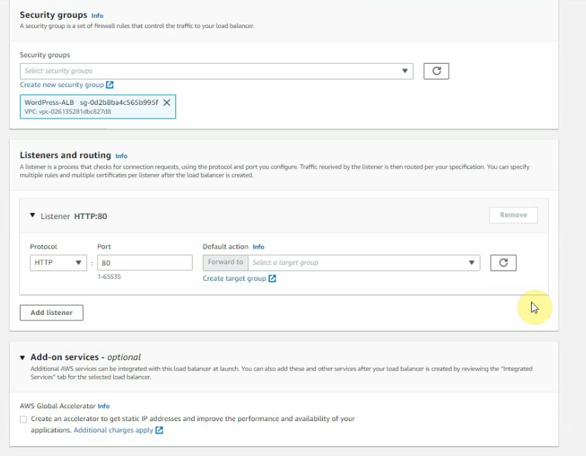
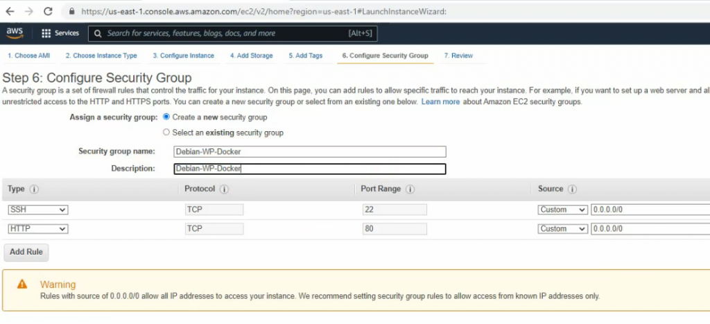
Go to the load balancer, and create a new application load balancer.
Create a new WordPress ALB SG. Allow HTTP from 0.0.0.0/0 on this Security Group.
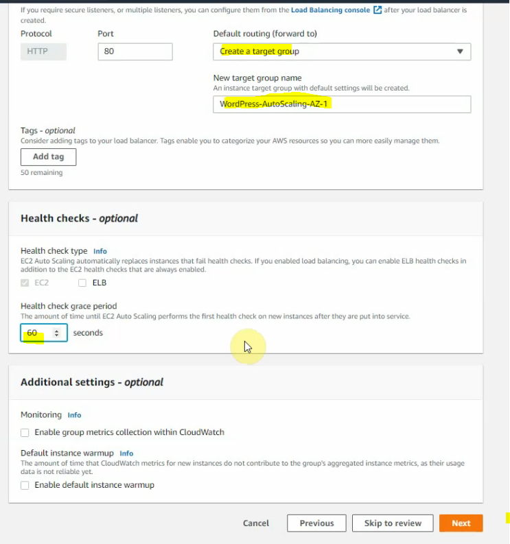
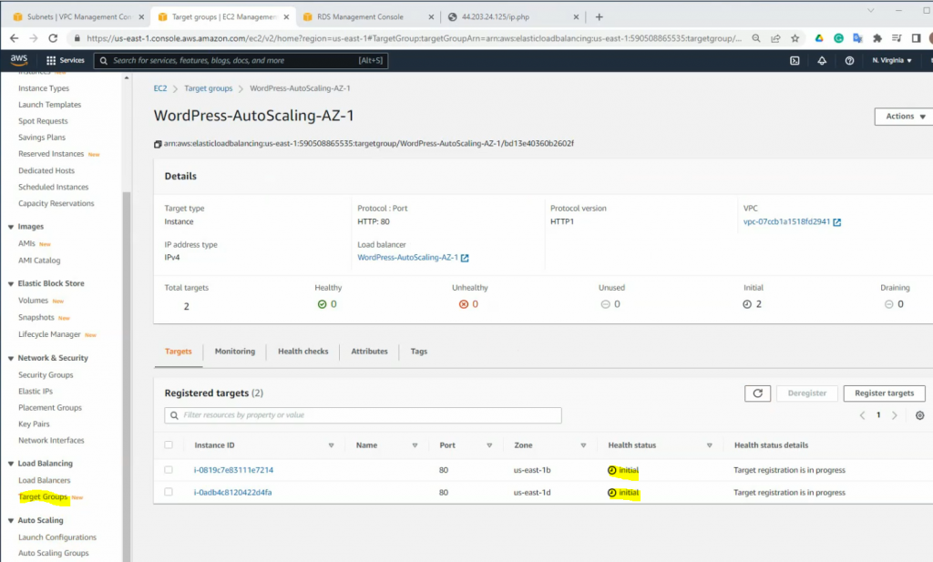
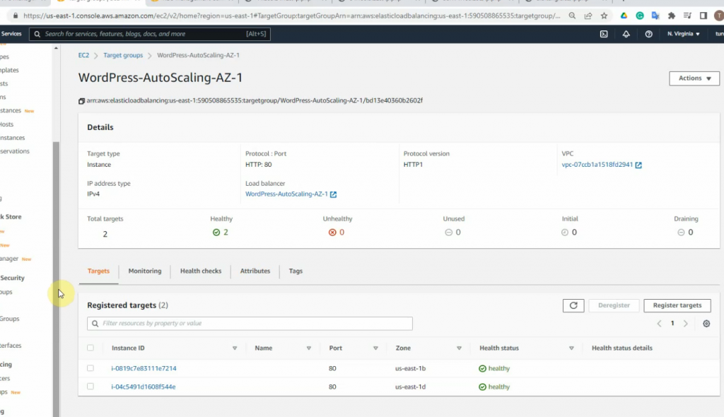
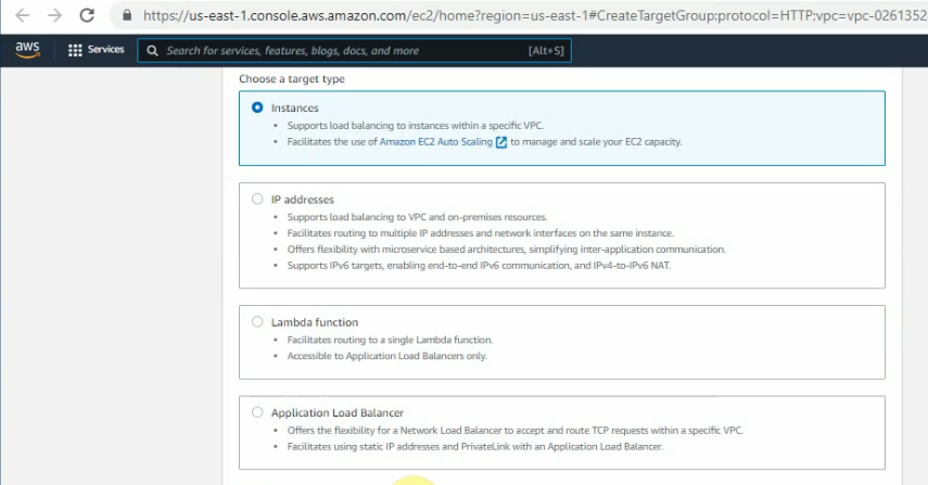
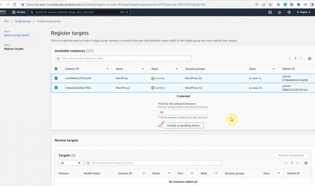
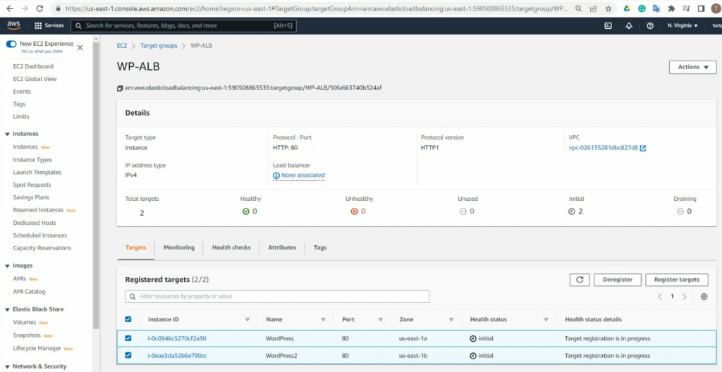
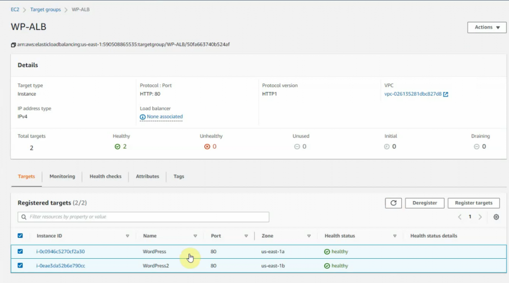
Create a target group.
Select “Instances”.
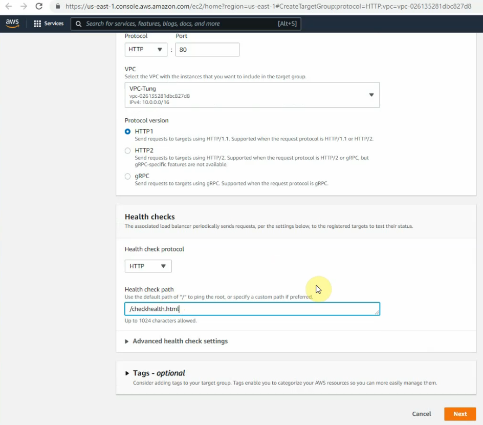
Enter “AP-ALB” on the target group name and checkhealth.html for the health check WP instance.
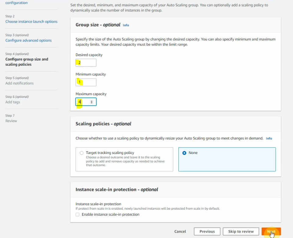
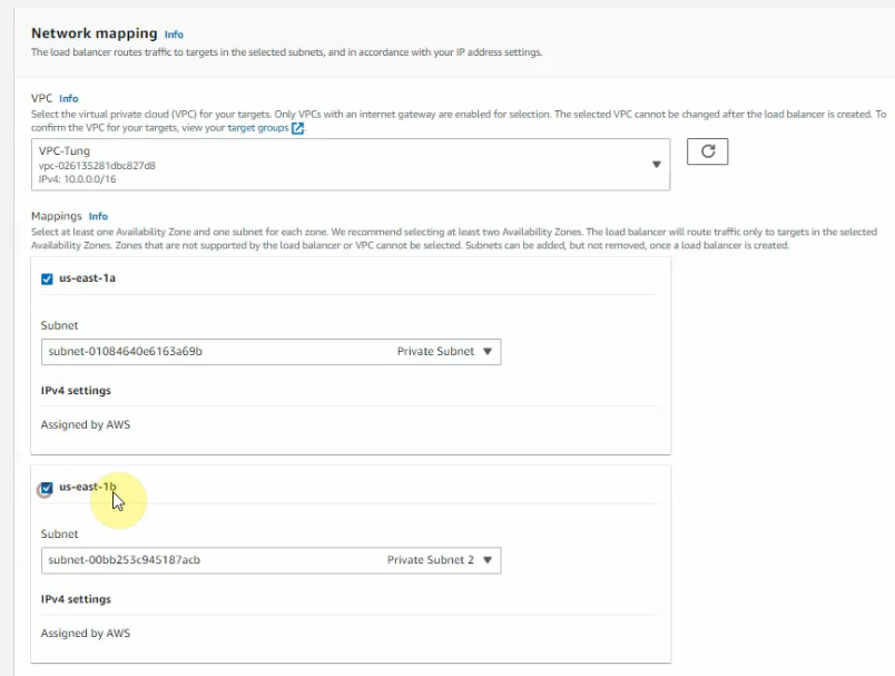
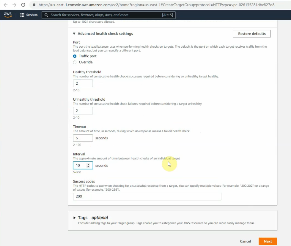
Change the settings as the screenshot below. Click Next.
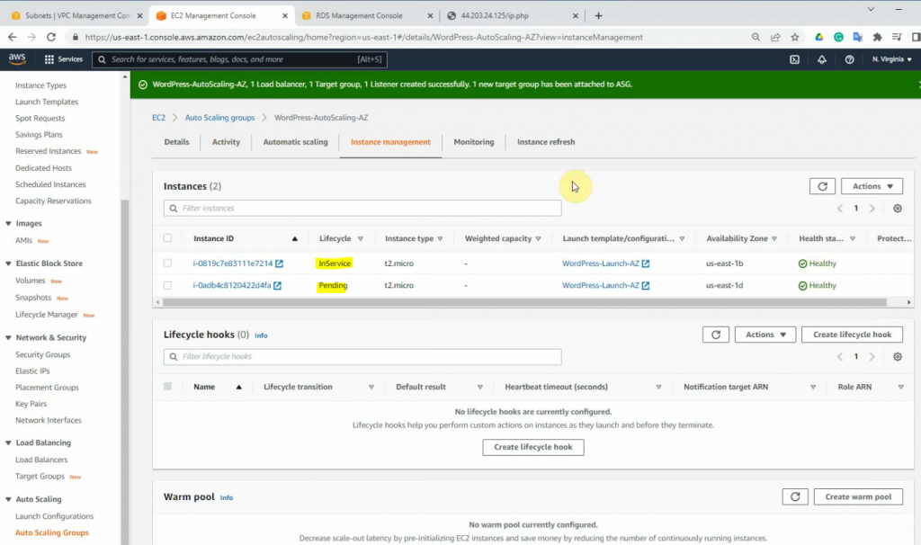
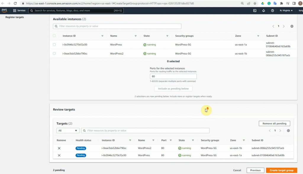
Select both instance IDs and click “Include as pending below”.
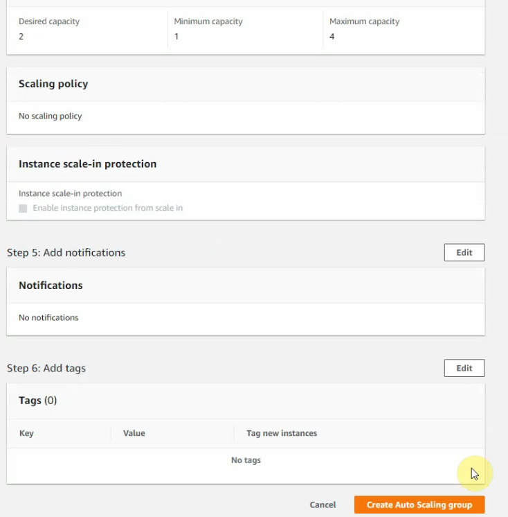
Create a target group.
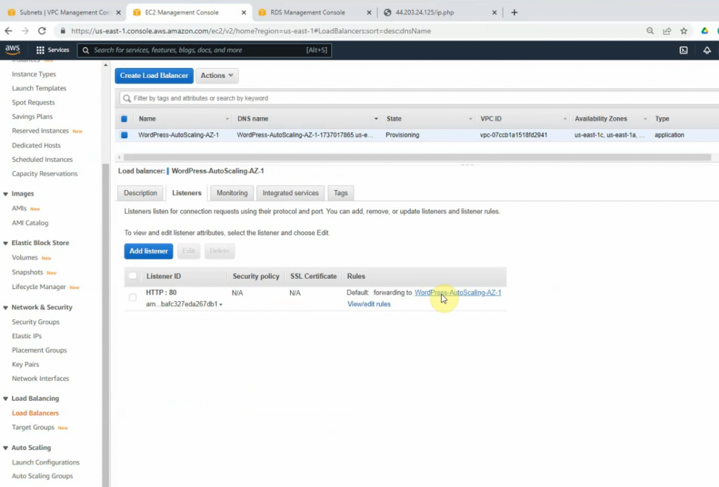
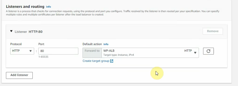
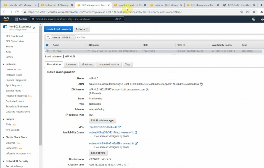
Back to the Application Load Balancer setup, choose the “WP-ALB” on the target group.
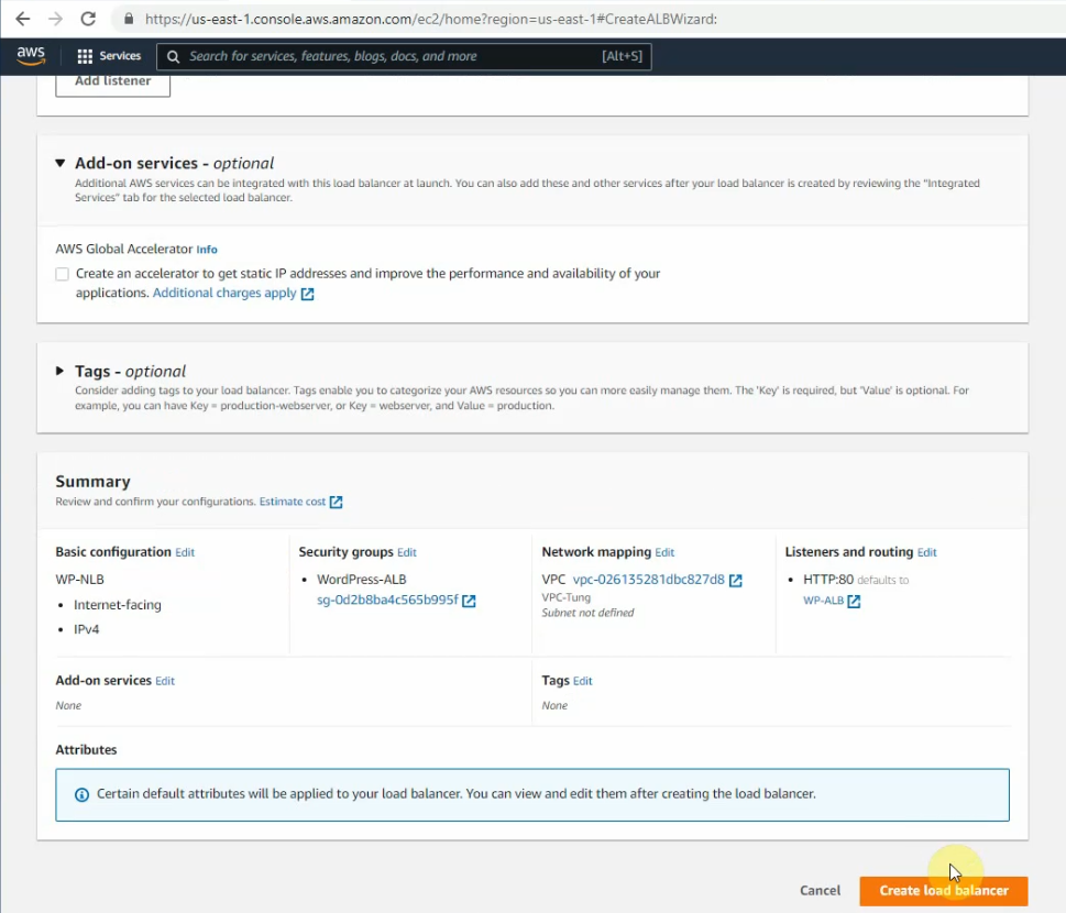
Create a load balancer.
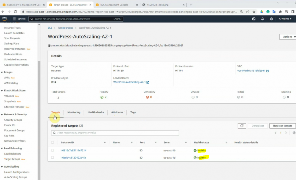
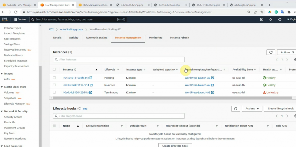
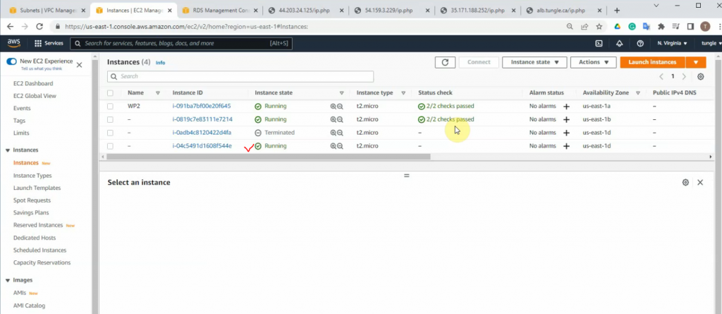
Wait a few minutes to see “Health status” is Healthy.
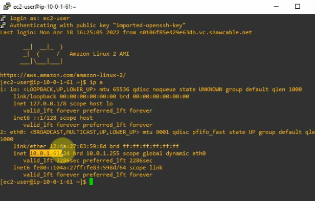
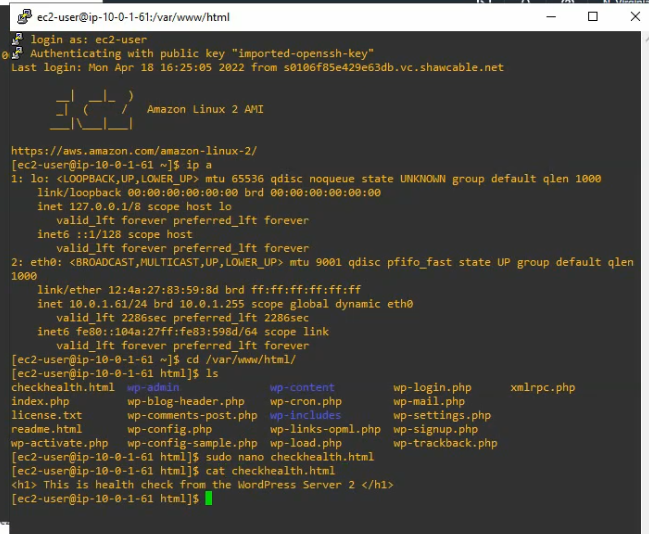
SSH to Linux instance on WordPress server 2.
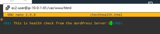
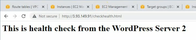
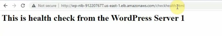
Change the checkhealth.html to make the difference between WP1 and WP2.
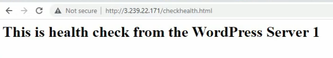
On WP1.
<h1> This is health check from the WordPress Server 1 </h1>
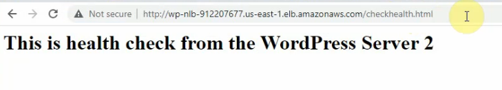
On WP server 2.
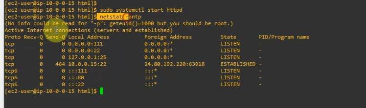
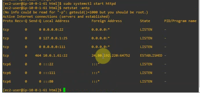
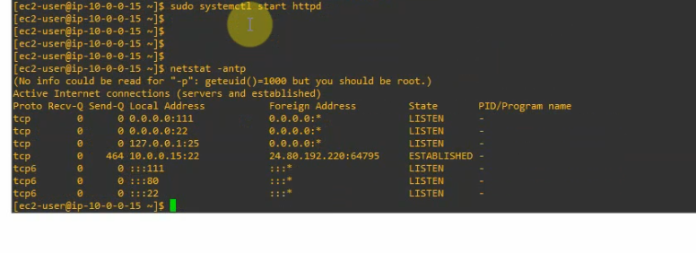
Start the httpd daemon.
sudo systemctl start httpd
Do the same on WP1 to make sure the httpd daemon is running after making the AMI template.
Access WP health check on WP server 1.
Make sure both WP servers have Healthy status on WP-ALB.
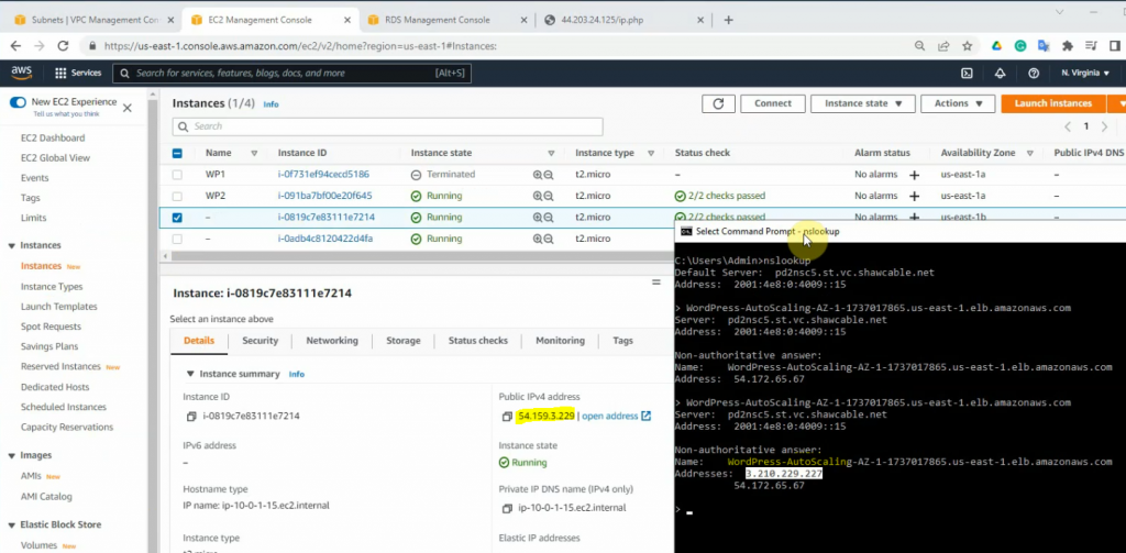
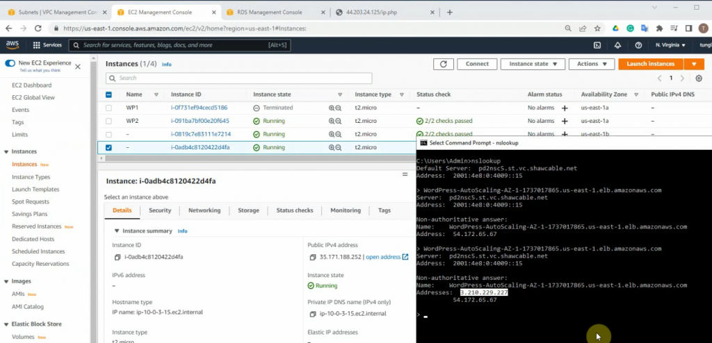
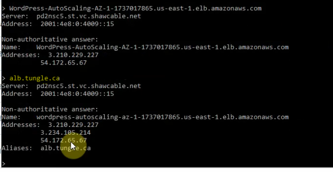
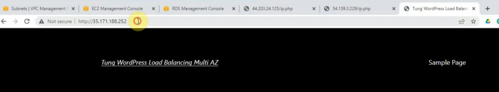
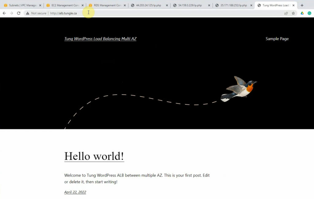
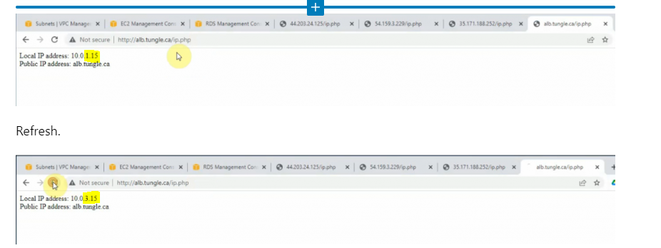
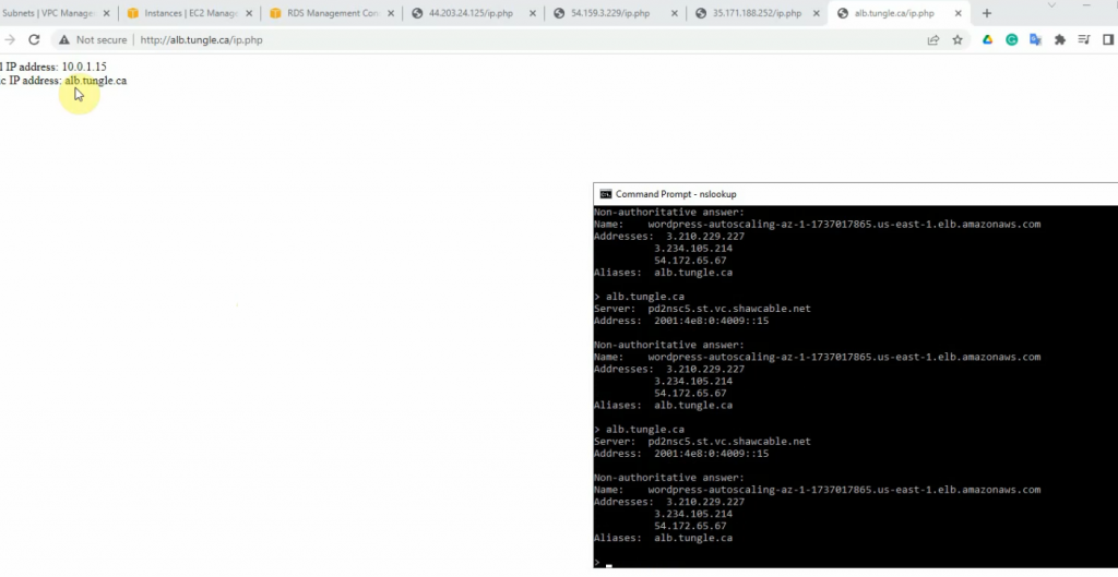
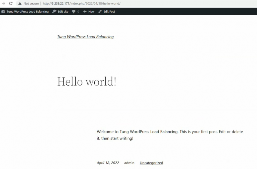
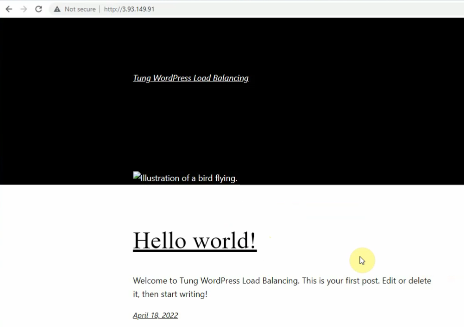
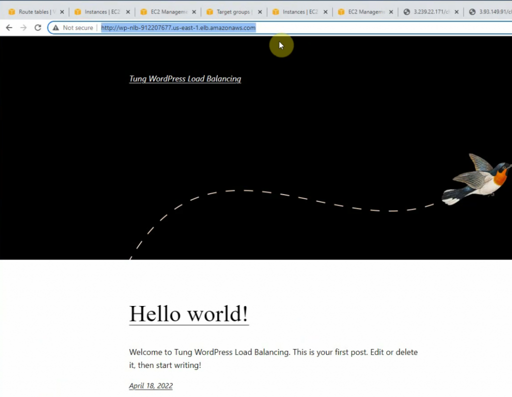
Copy the Amazon ALB link into your web browser.
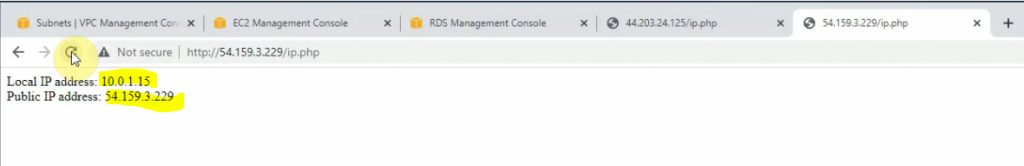
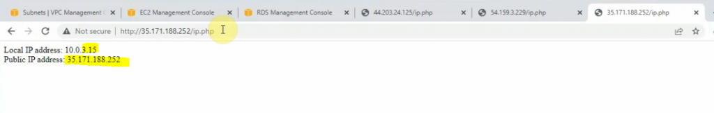
Refresh, it can be seen that the web traffic is loaded balancing on the WP server 2.
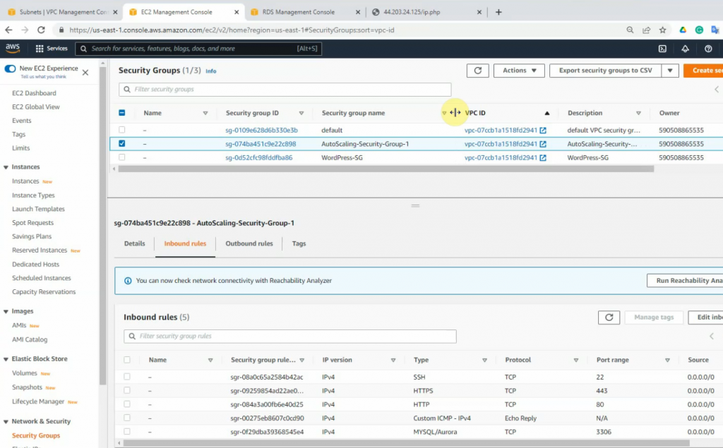
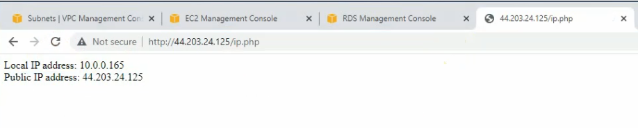
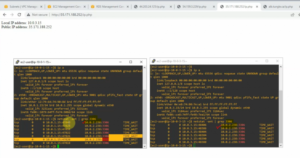
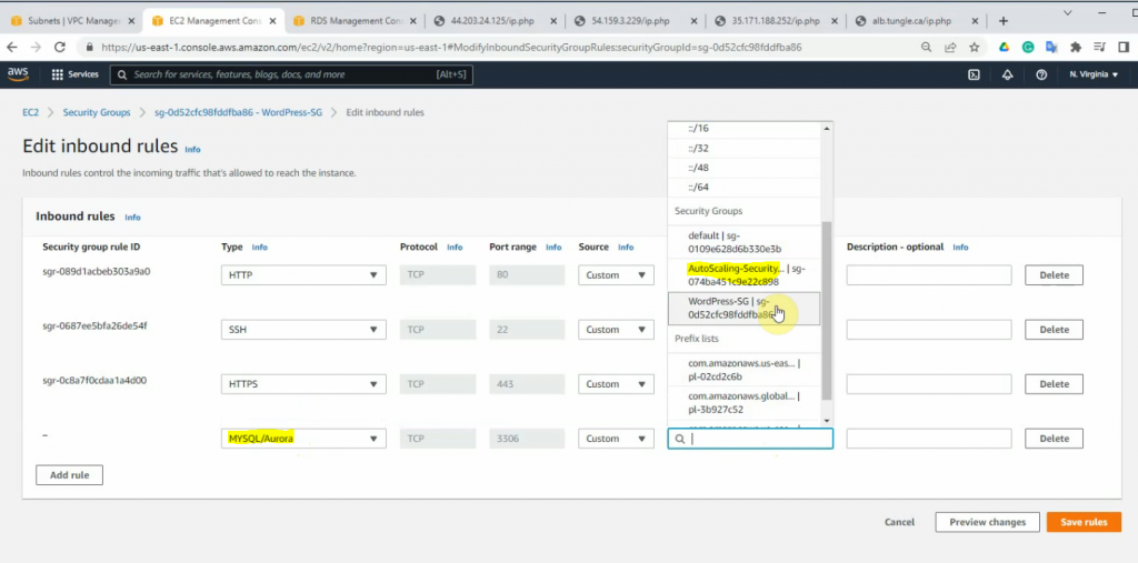
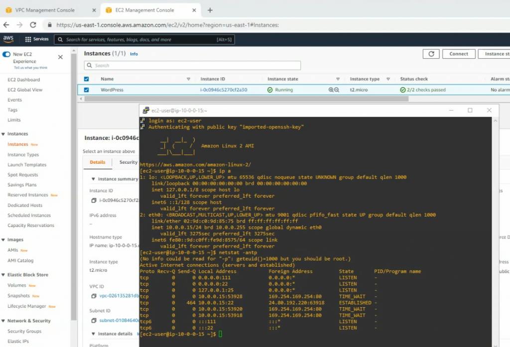
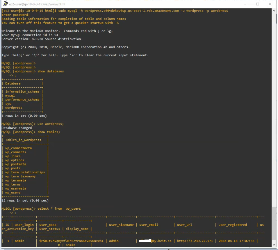
Check the connection from WP instances to the Amazon RDS database.
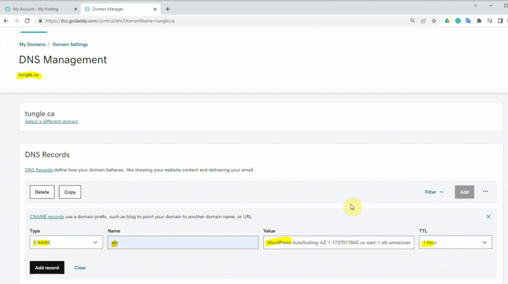
I will set up Amazon Route 53, Amazon CloudFront with a real domain name such as awsbigfan.ca, and load balancing via HTTPS (WordPress SSL certificate will be issued by Amazon), not HTTP. Also. I will configure a strict Security Group policy to strengthen security from WordPress to the Amazon RSD database in the next labs.
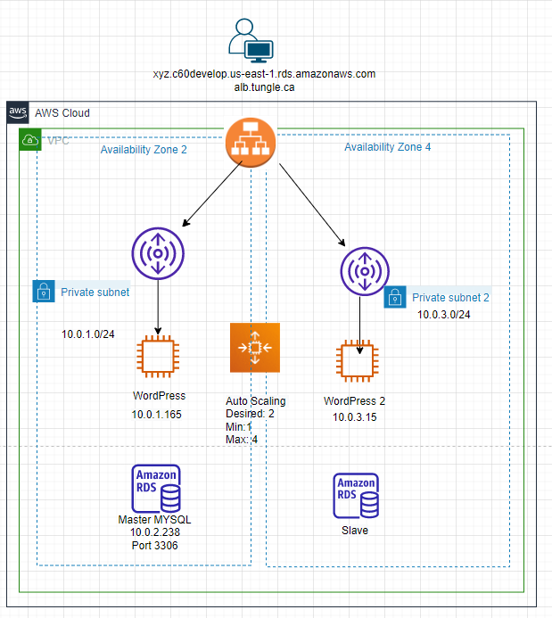
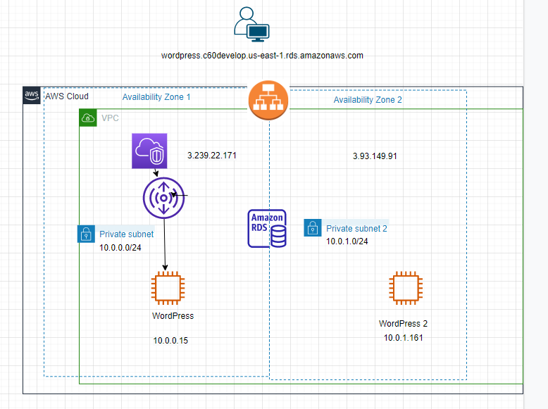
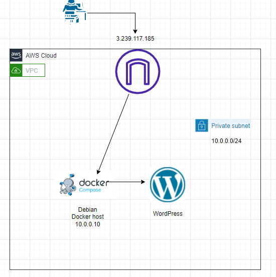
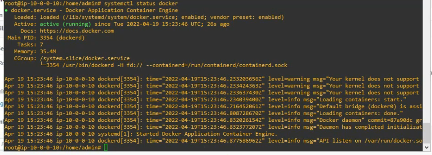
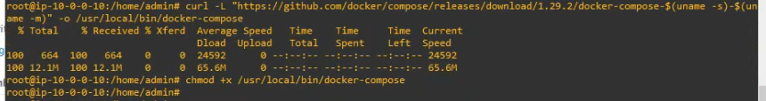
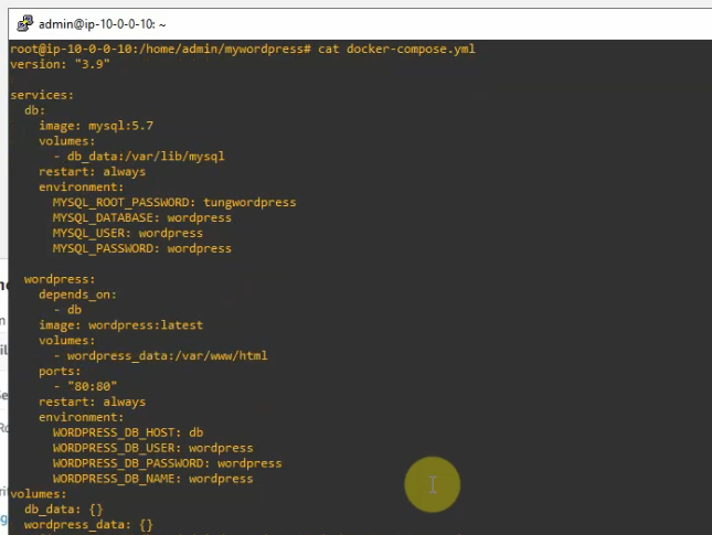
I have explained how to use Docker compose to deploy WordPress on-prem (https://tungle.ca/?p=2381). In this article, I will install docker on the Debian Linux instance on AWS, then deploy WordPress via this docker.
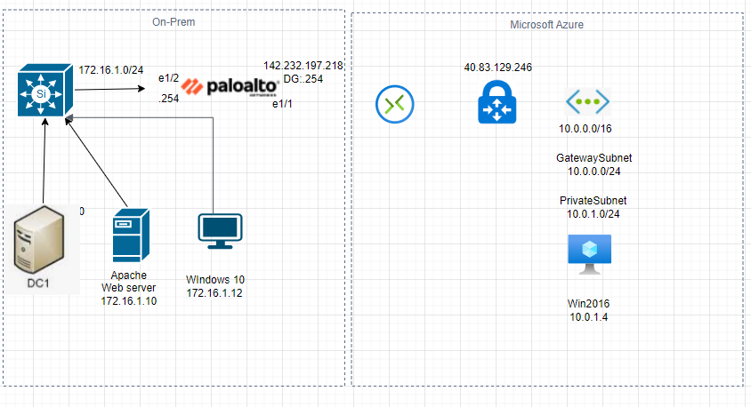
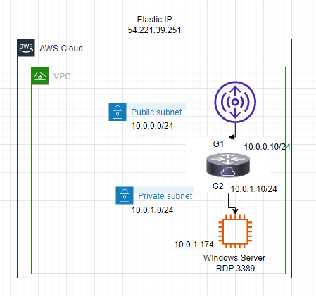
Below is a diagram that I have used to deploy this lab.
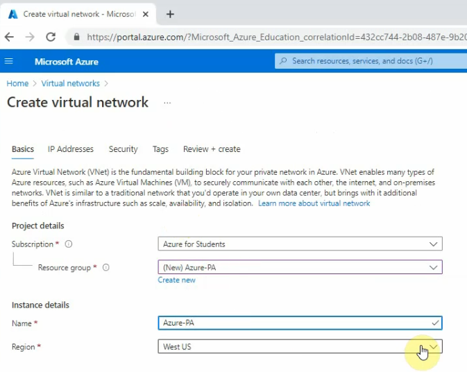
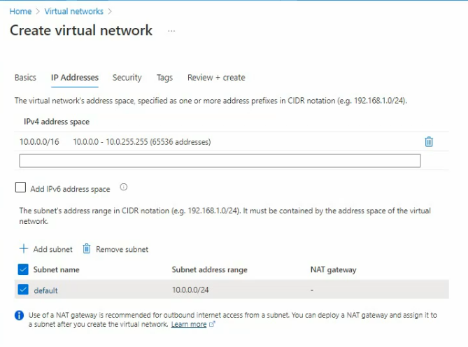
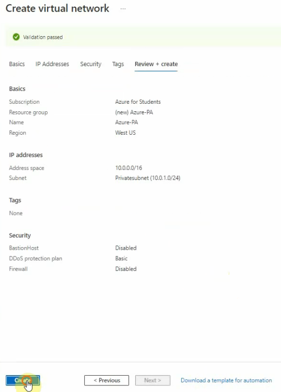
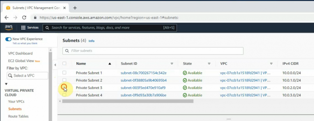
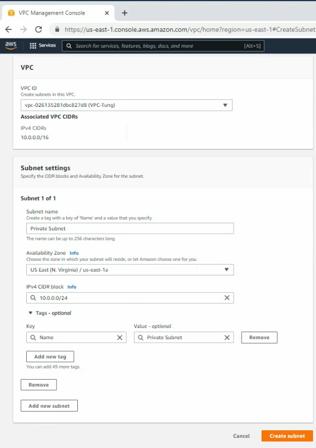
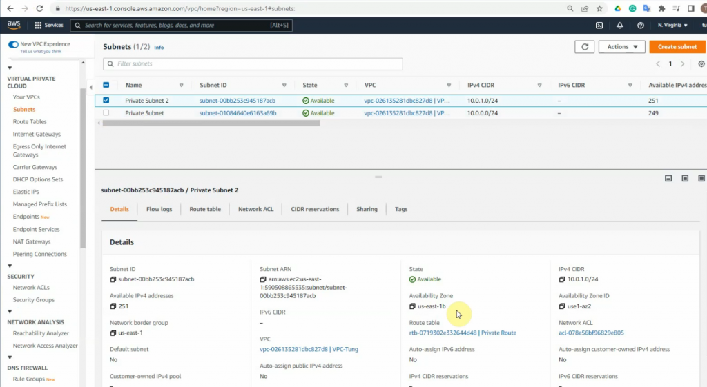
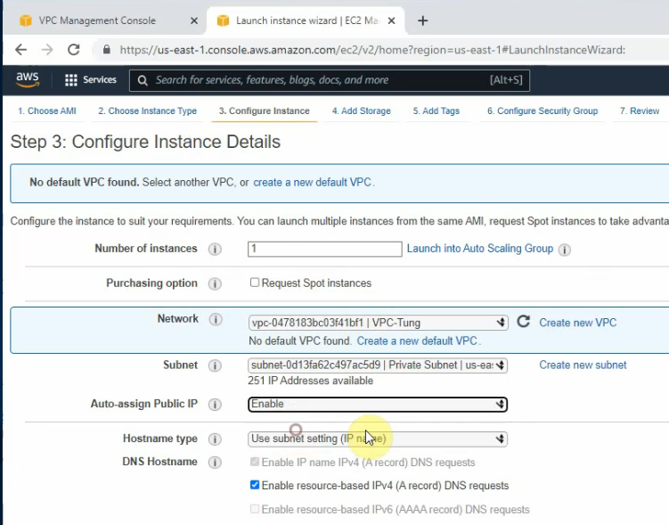
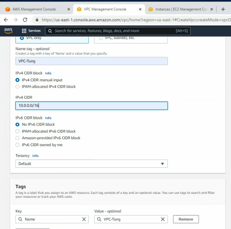
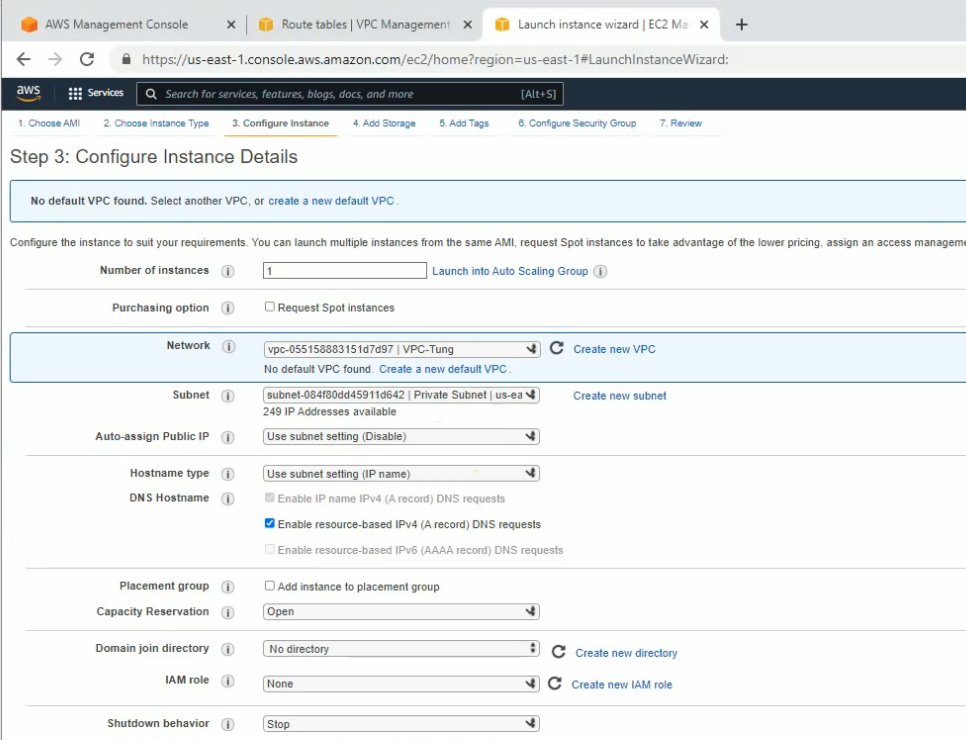
Create a new VPC.
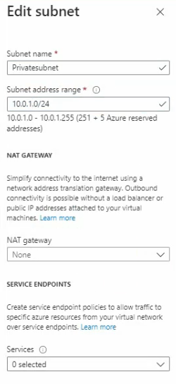
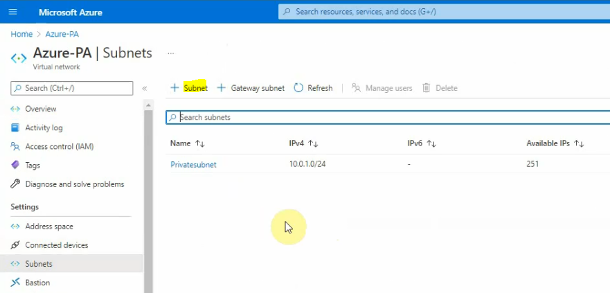
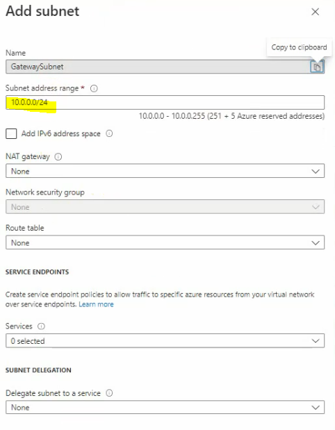
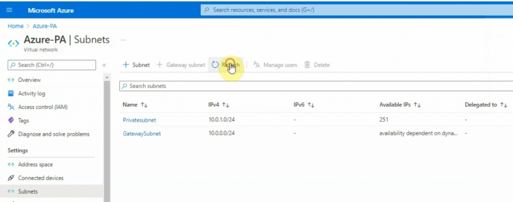
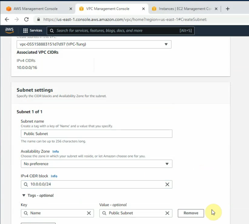
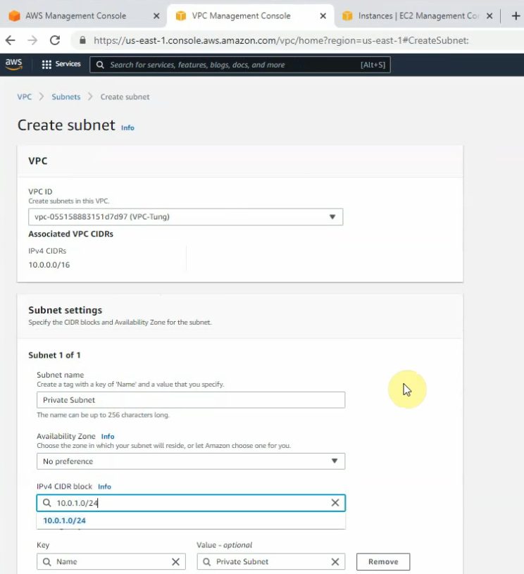
New Public subnet and Private subnet.
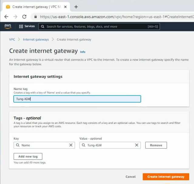
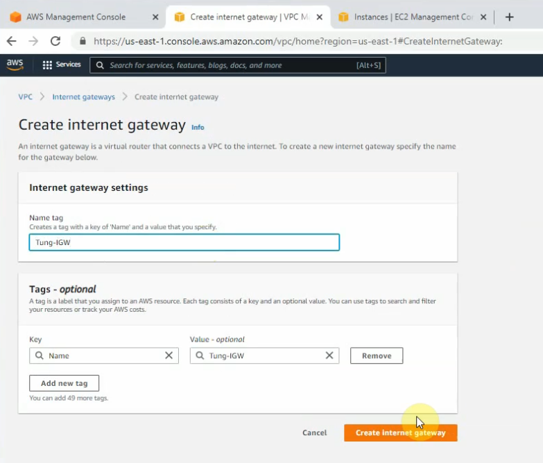
Create and attach a new Internet gateway to your VPC.
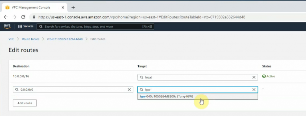
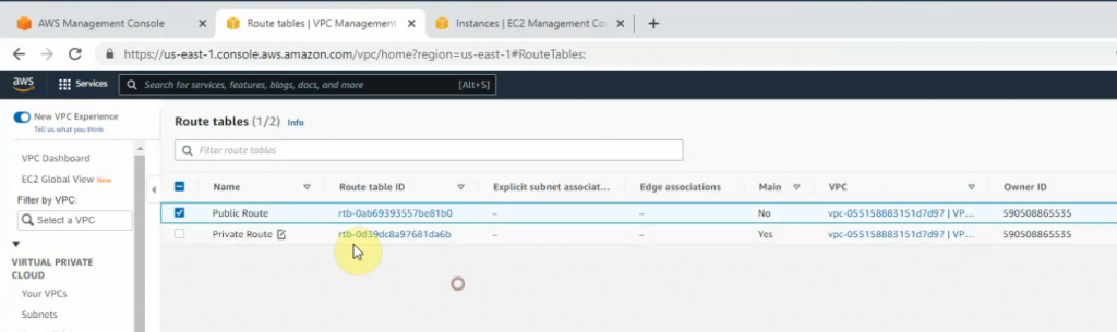
Create a new Public Route table.
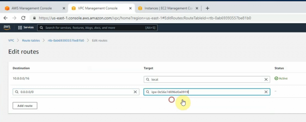
Create a new route to 0.0.0.0/0 to your Internet gateway.
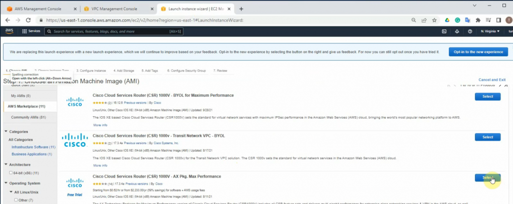
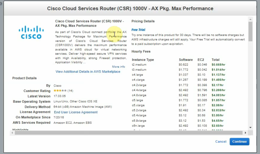
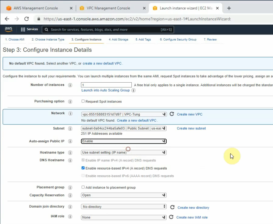
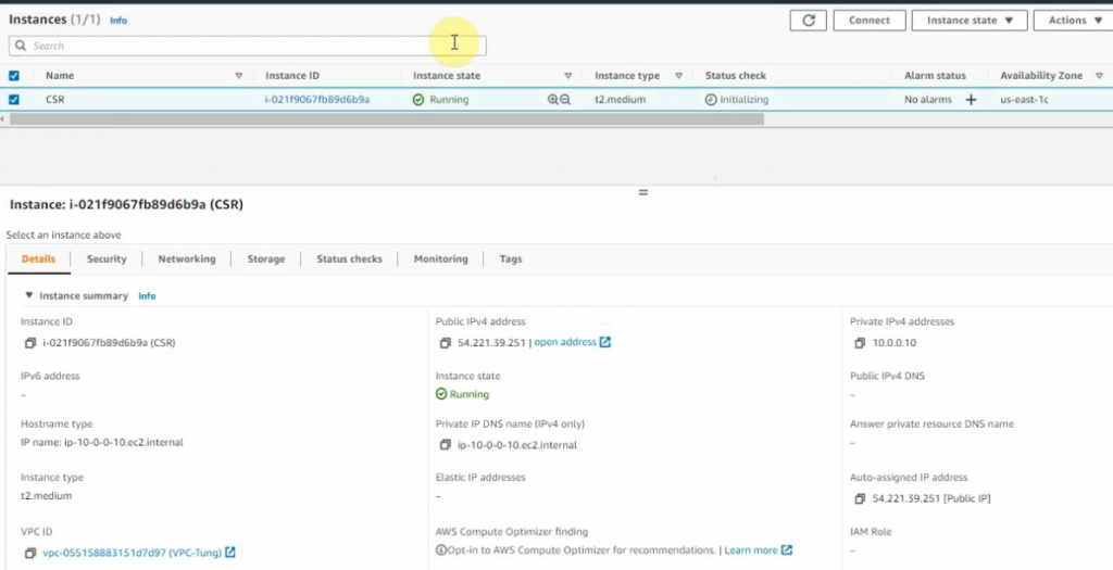
Launches a new CSR instance.
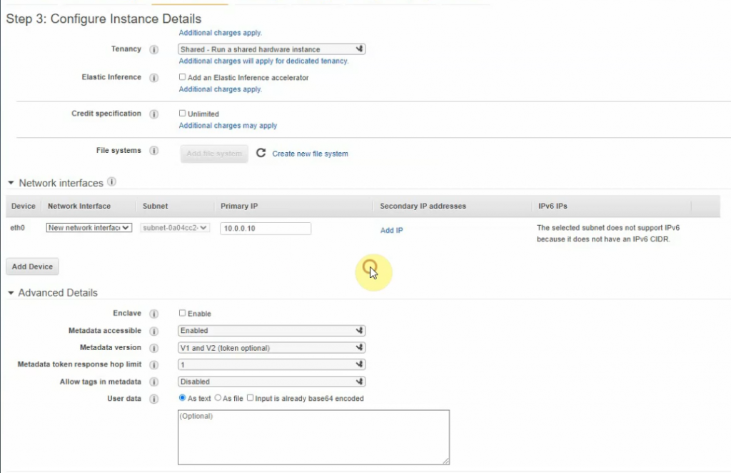
Enter 10.0.0.10 on Primary IP setting.
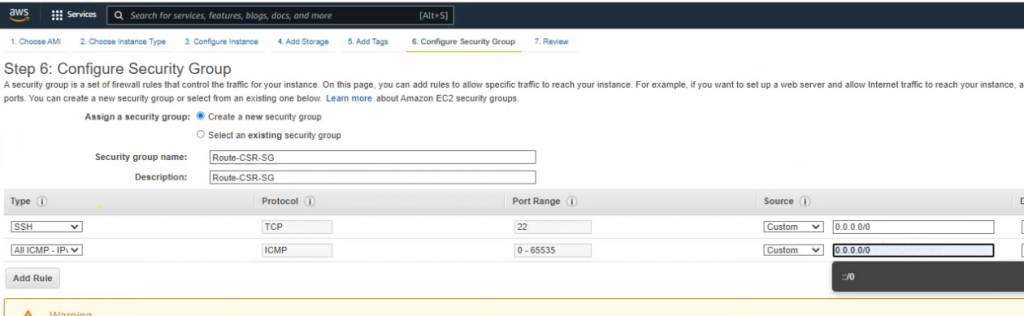
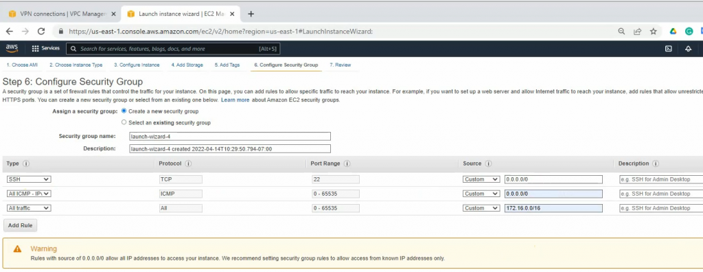
Security Group.
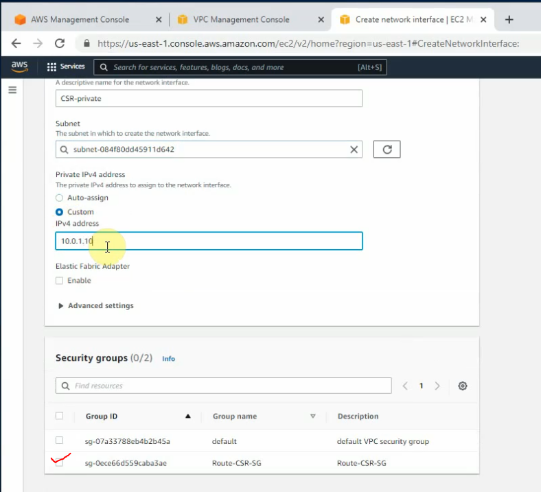
Go to Network interfaces, and create a new network interface for Router CSR.
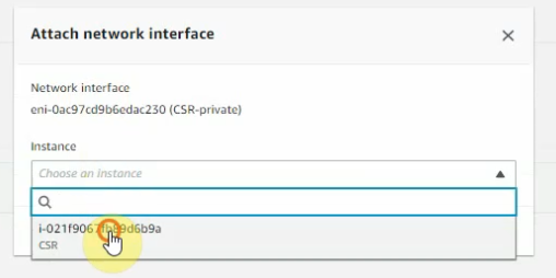
Then attach this network to Router CSR.
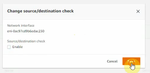
Disable “Change/source/dest check” for both Cisco CSR interfaces.
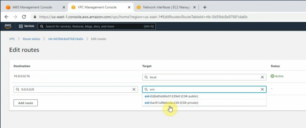
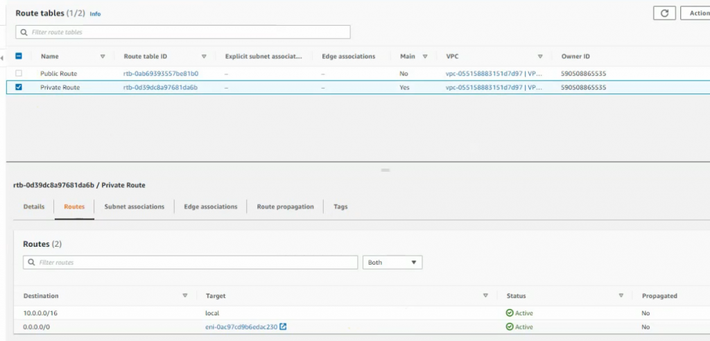
Back to route tables, configure the new route to the private Cisco CSR interface.
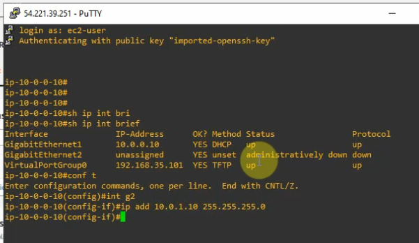
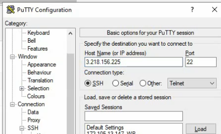
SSH from putty to Cisco Router.
conf t
int g2
ip add 10.0.1.10 255.255.255.0
no shut
exit
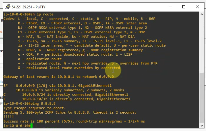
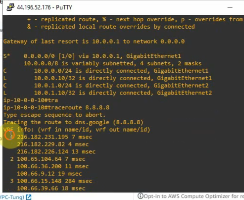
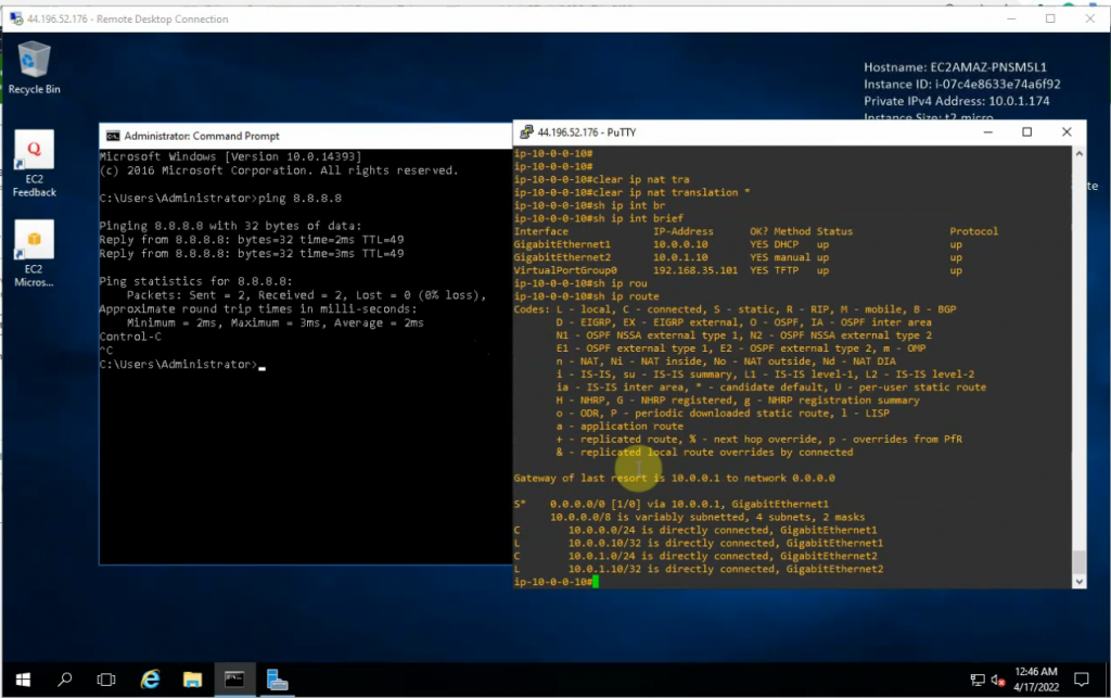
ping 8.8.8.8
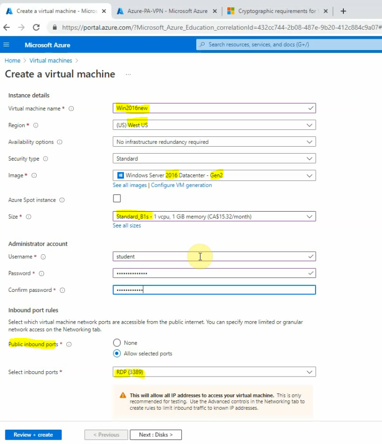
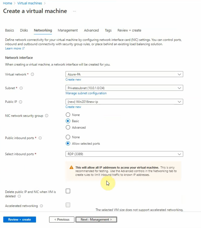
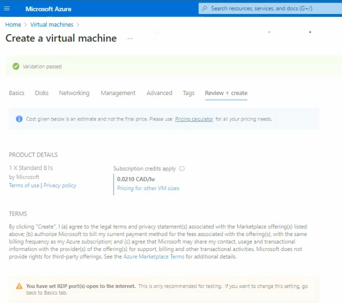
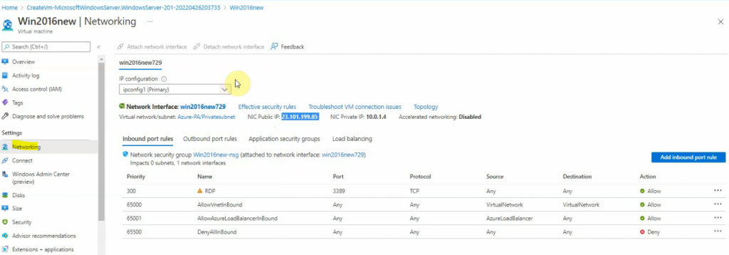
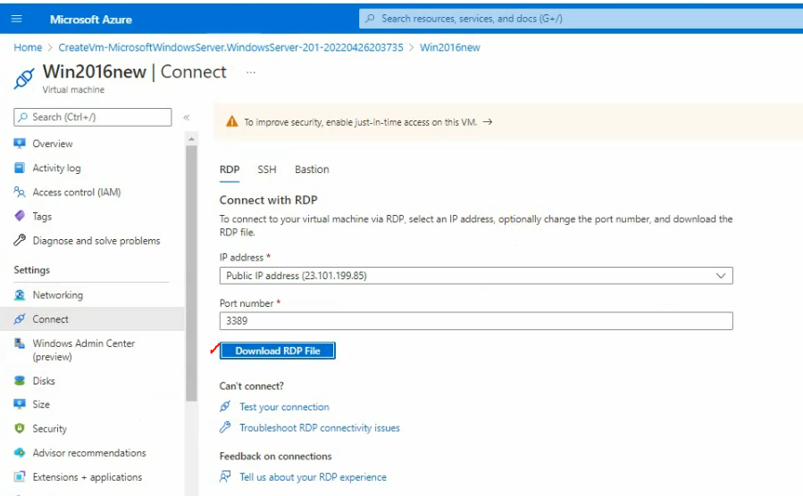
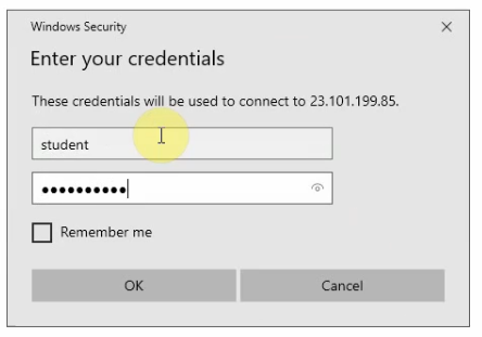
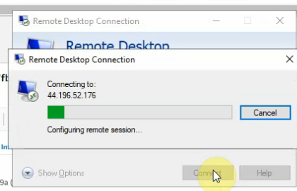
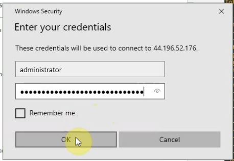
Launches a new Windows 2016 machine to test RDP traffic from the Internet.
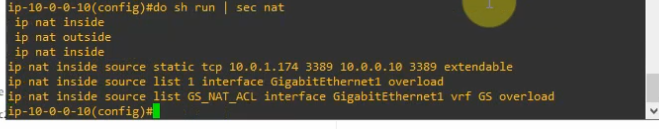
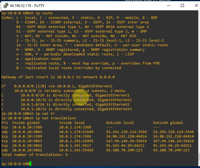
Enable SNAT and DNAT on the Router.
conf t
access-list 1 permit any
# Allow inside to outside
ip nat inside source list 1 interface g1 overload
# Allow outside to Windows server via the RDP service
ip nat inside source static tcp 10.0.1.174 3389 10.0.0.10 3389
int g1
ip nat outside
int g2
ip nat inside
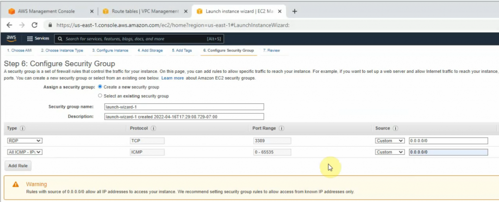
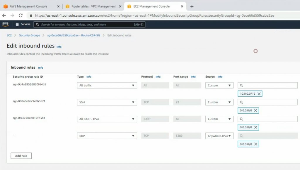
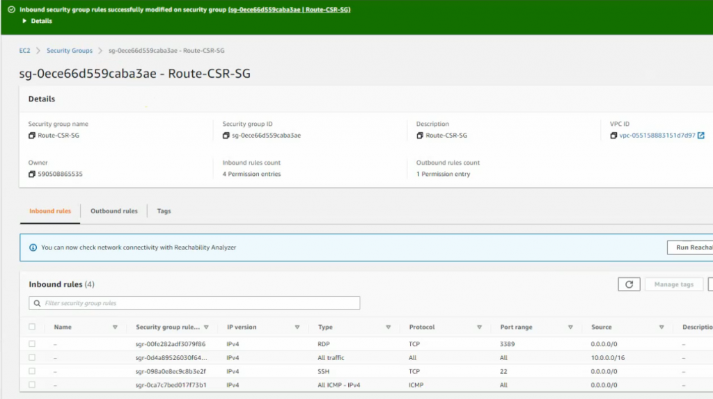
Edit Router CSR Security Group and add RDP service into this group to allow RDP traffic from the Internet.
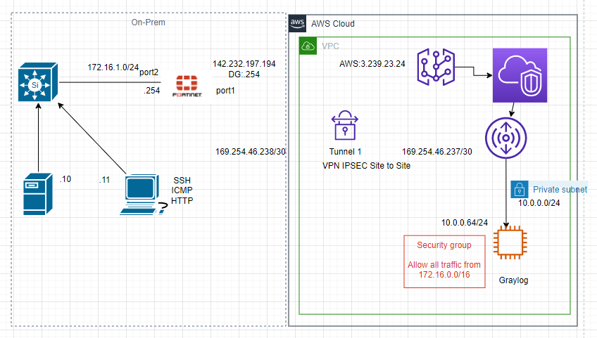
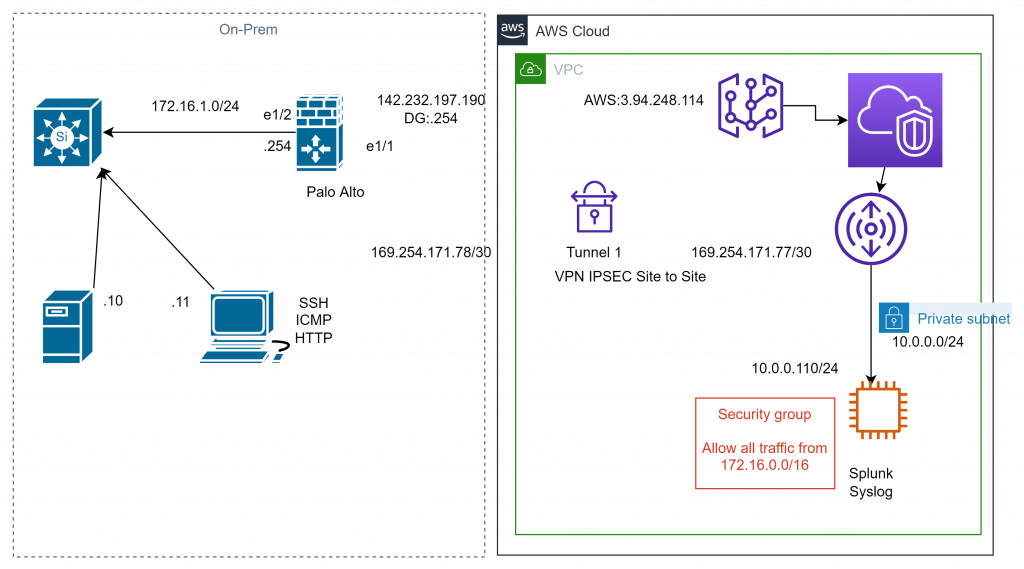
This is a diagram that I have used to deploy this lab.
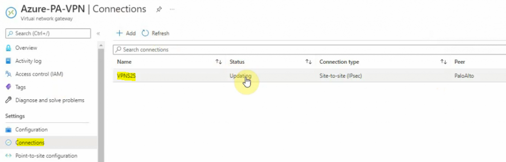
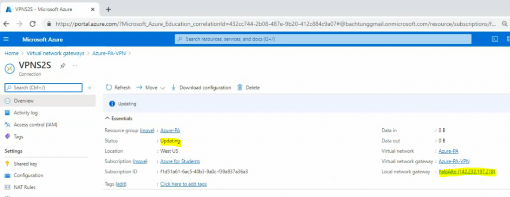
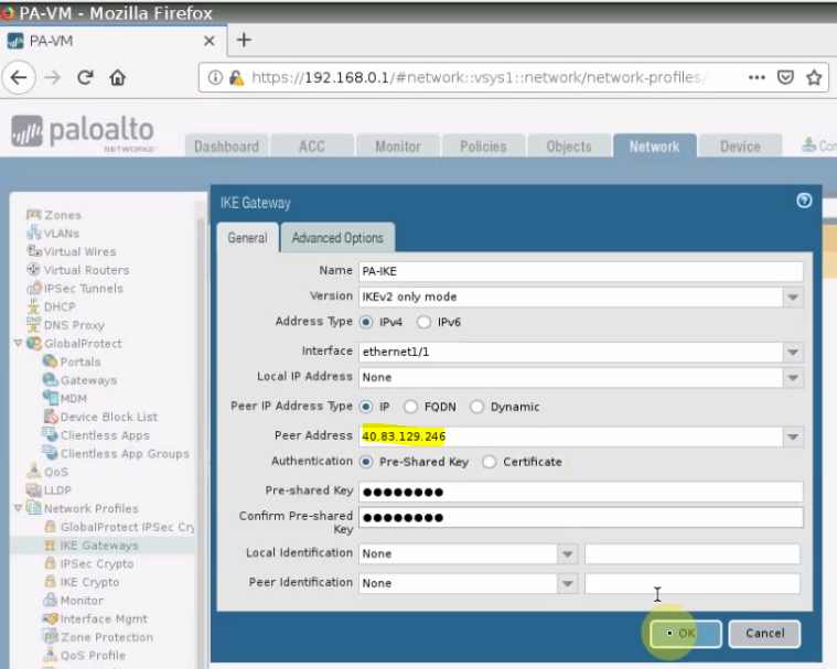
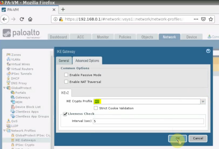
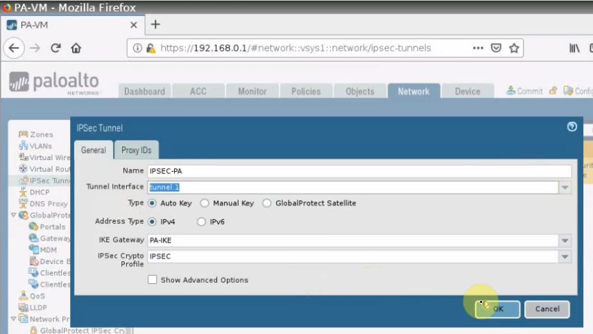
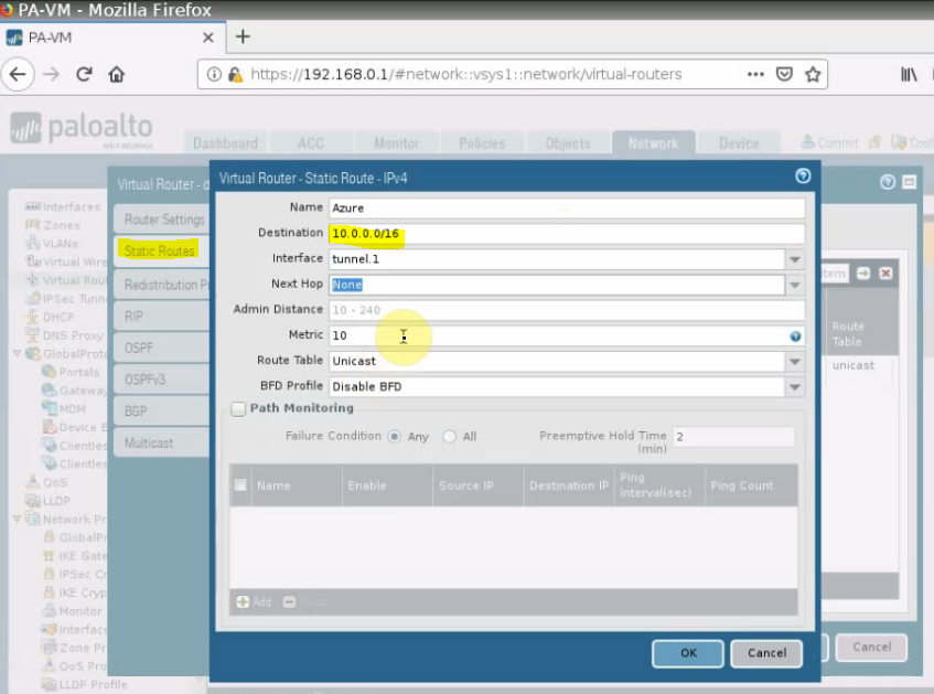
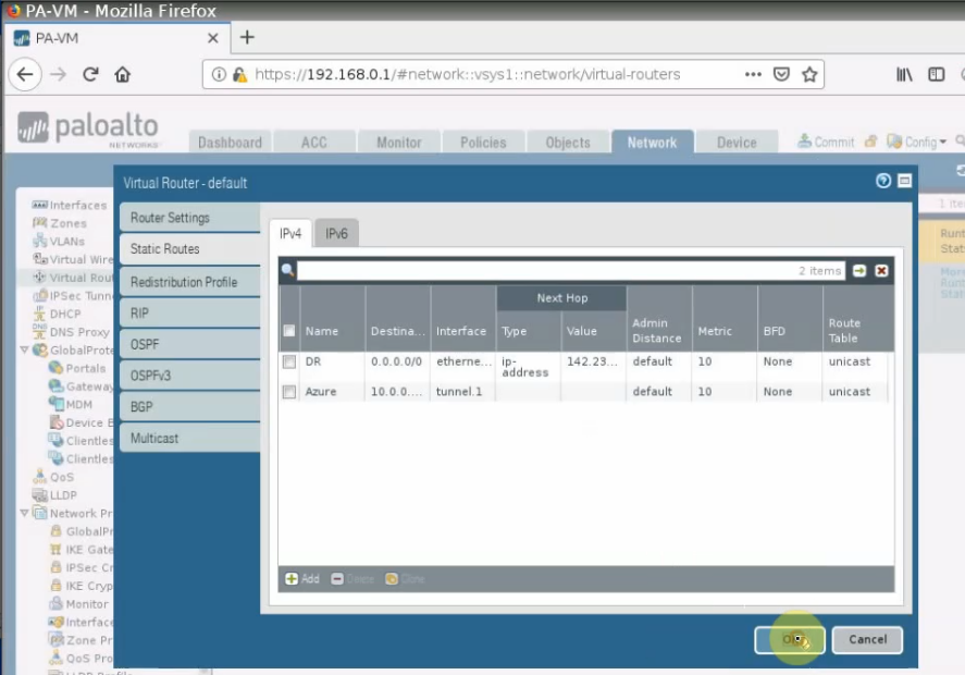
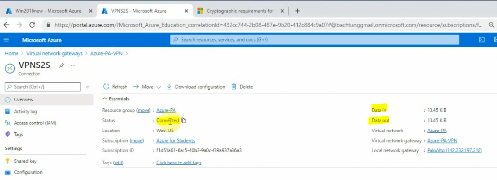
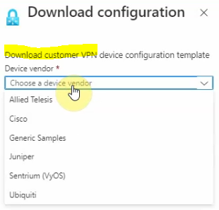
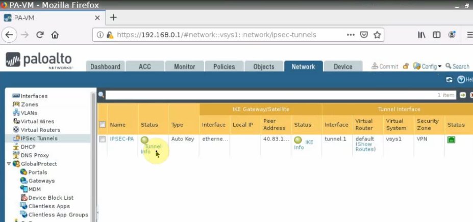
We need to deploy a VPN site to site between Palo Alto on-prem and AWS.
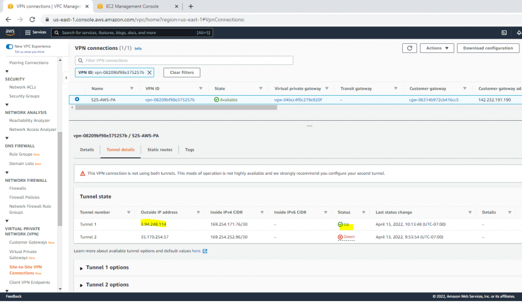
On AWS.
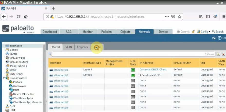
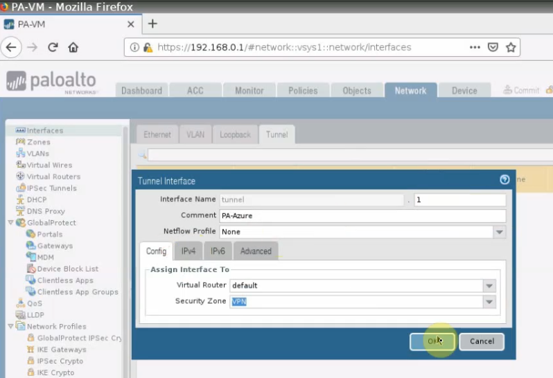
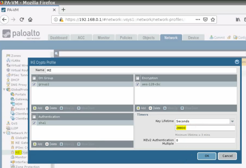
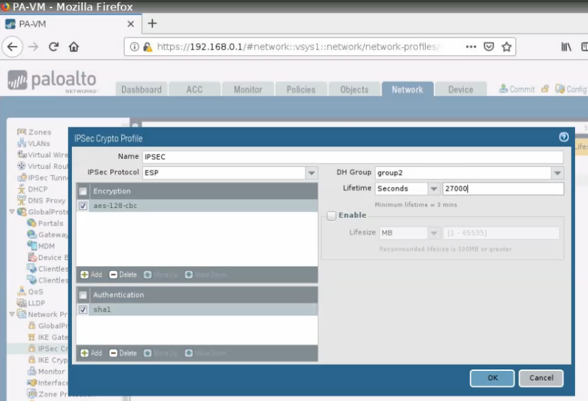
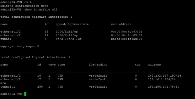
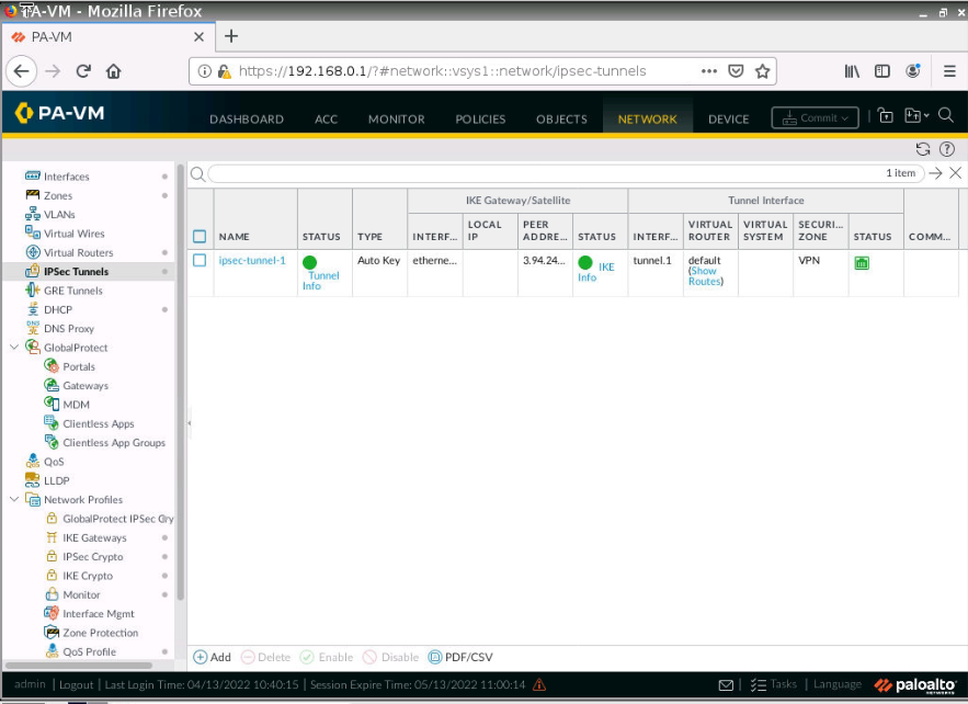
On Palo Alto.
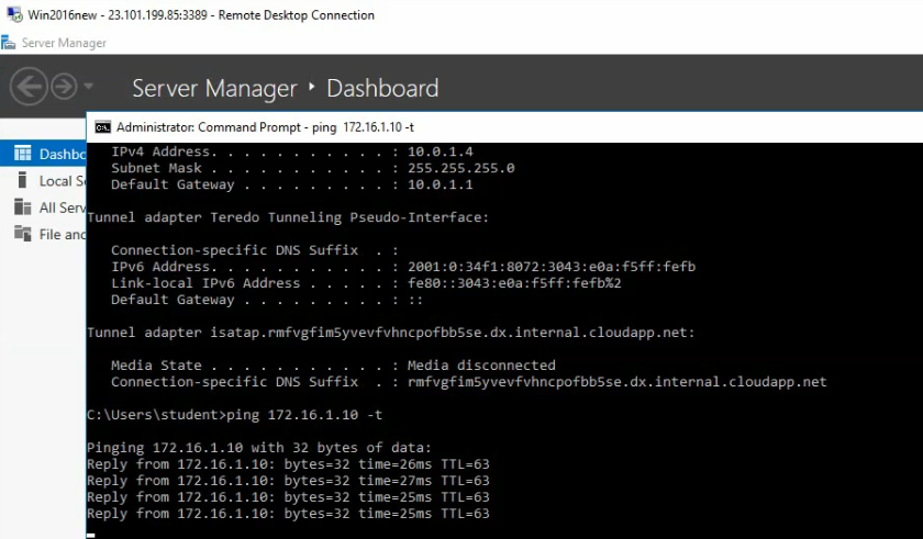
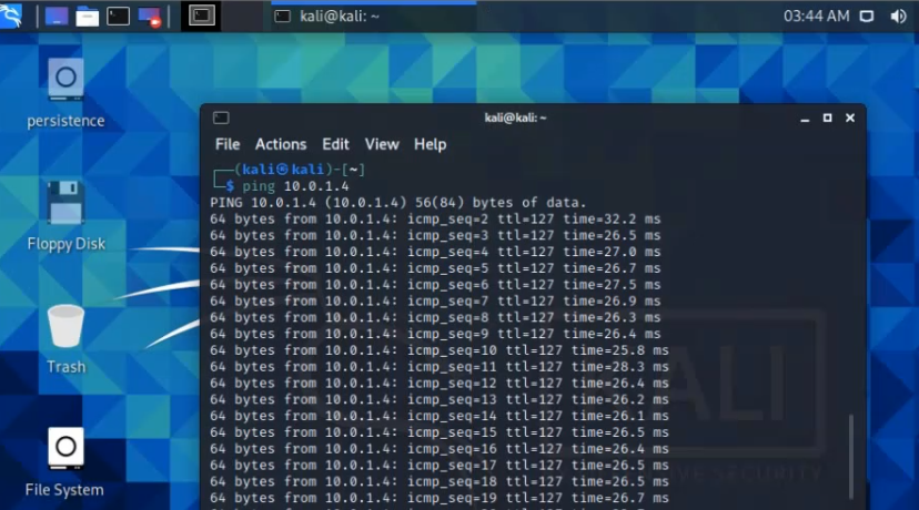
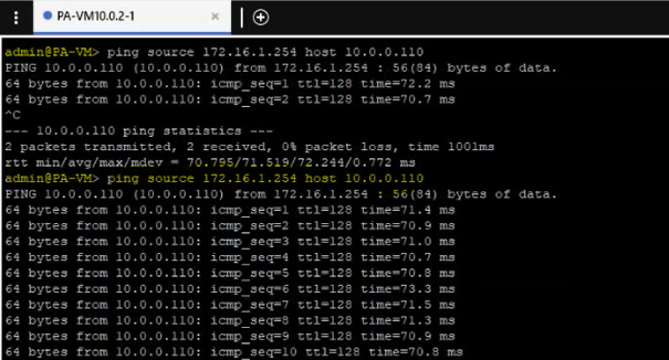
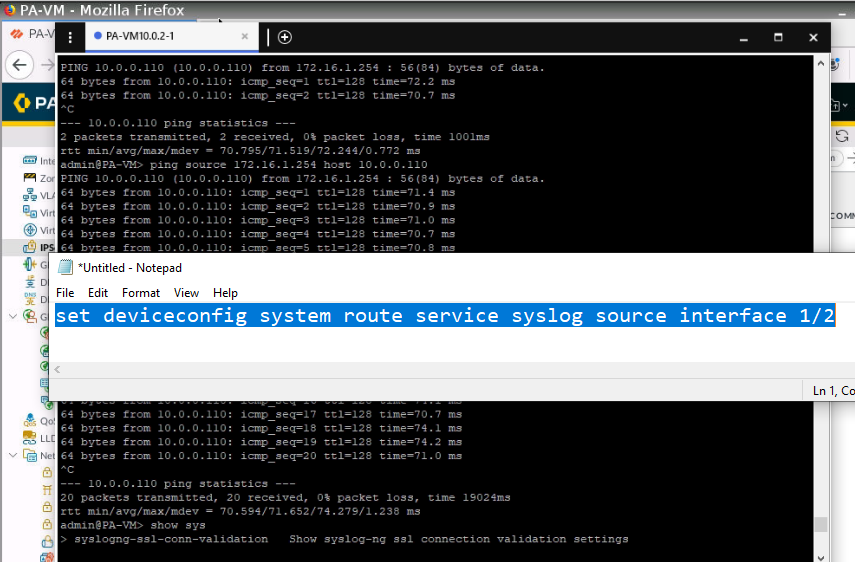
Pings Splunk instance (10.0.0.110) via ethernet 1/2 interface.
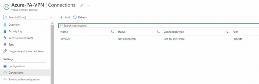
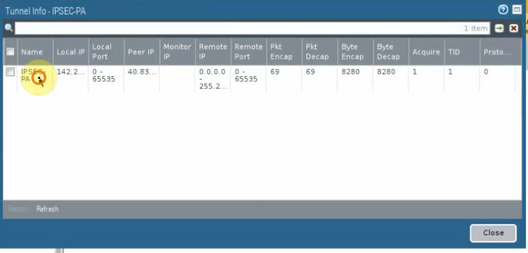
The VPN site-to-site tunnel is up in Palo Alto.
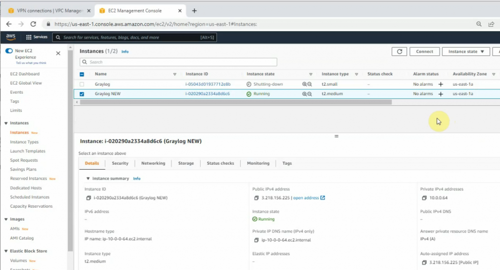
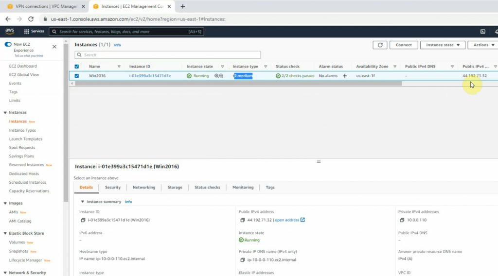
Set up a new Windows 2016 instance with 4 GB memory to run Splunk Enterprise on AWS.
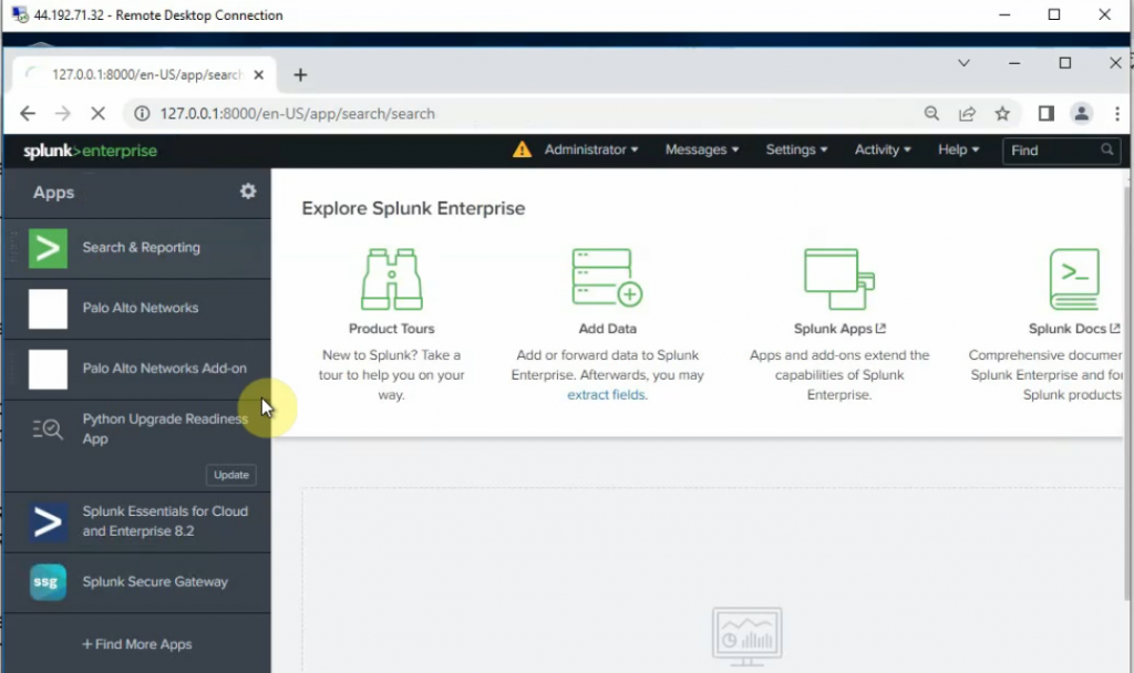
RDP to the instance and install Splunk Enterprise. Then, add Splunk for Palo Alto on this instance.
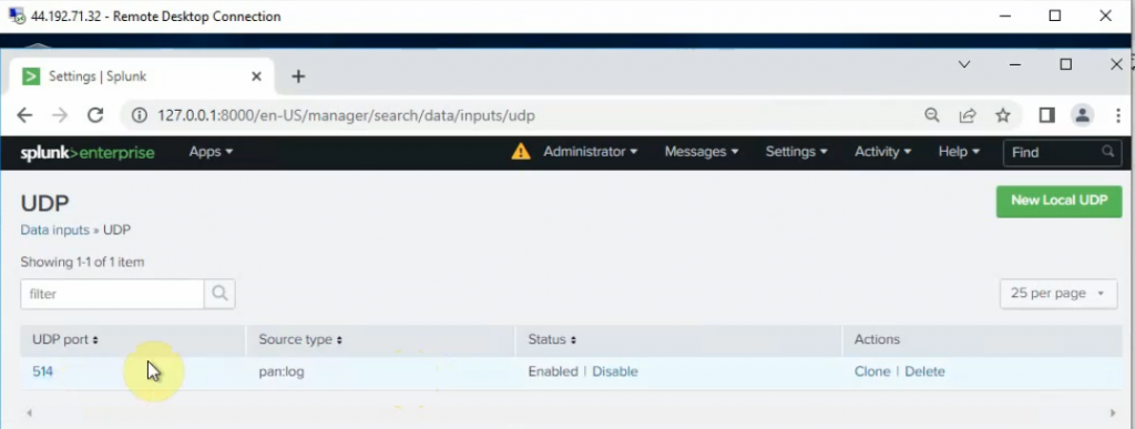
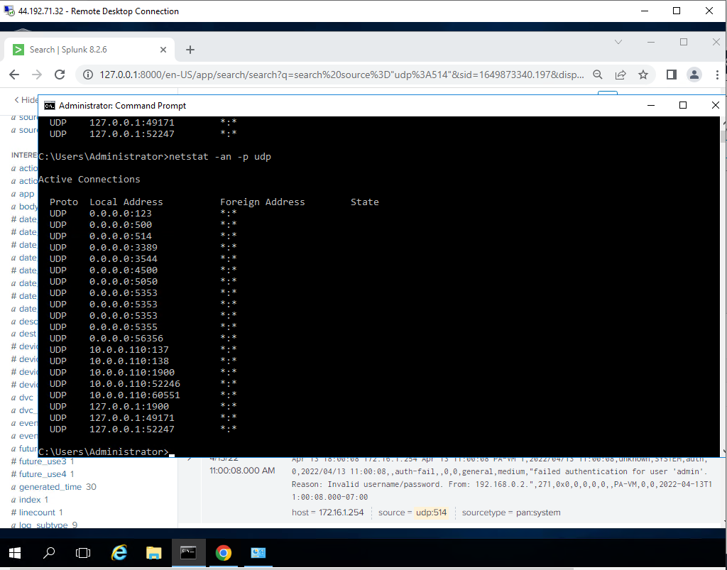
Configure Splunk to get Palo Alto logs via UDP port 514.
Check the UDP 514 port is running on the Splunk instance.
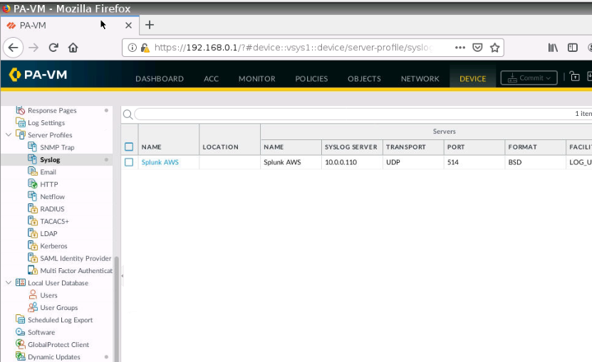
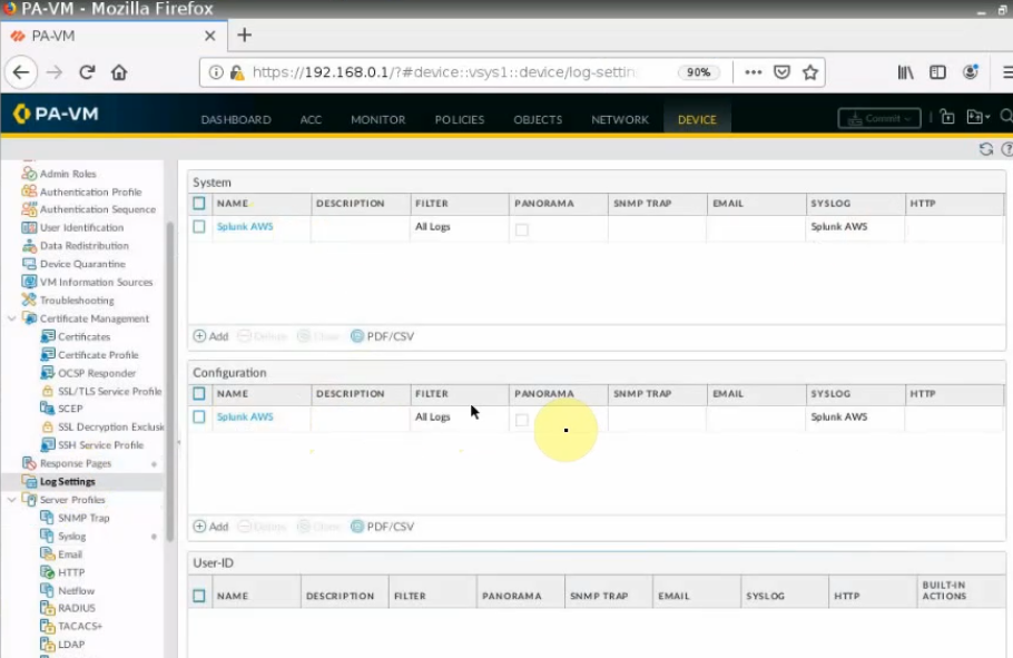
Go to Palo Alto, and configure Syslog to send logs to Splunk.
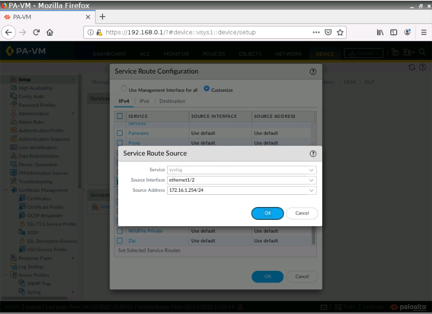
By default, Palo Alto uses a management interface to send logs. We need to change the interface to allow Palo Alto to send logs via ethernet1/2 (LAN interface).
Log on PA console, type configure, and the command below to change the interface to send logs.
set deviceconfig system route service syslog source interface e1/2
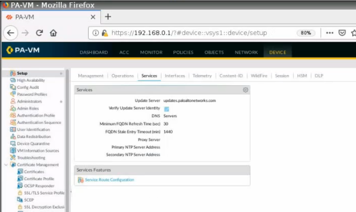
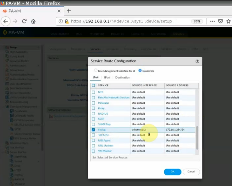
Also, we can go to Device – Setup – Service Route Configuration – Syslog. Configure the source interface and source IP address like the following screenshot.
Configure Syslog on Palo Alto.
IP address: 10.0.0.110 (Splunk instance)
Port: 514 UDP
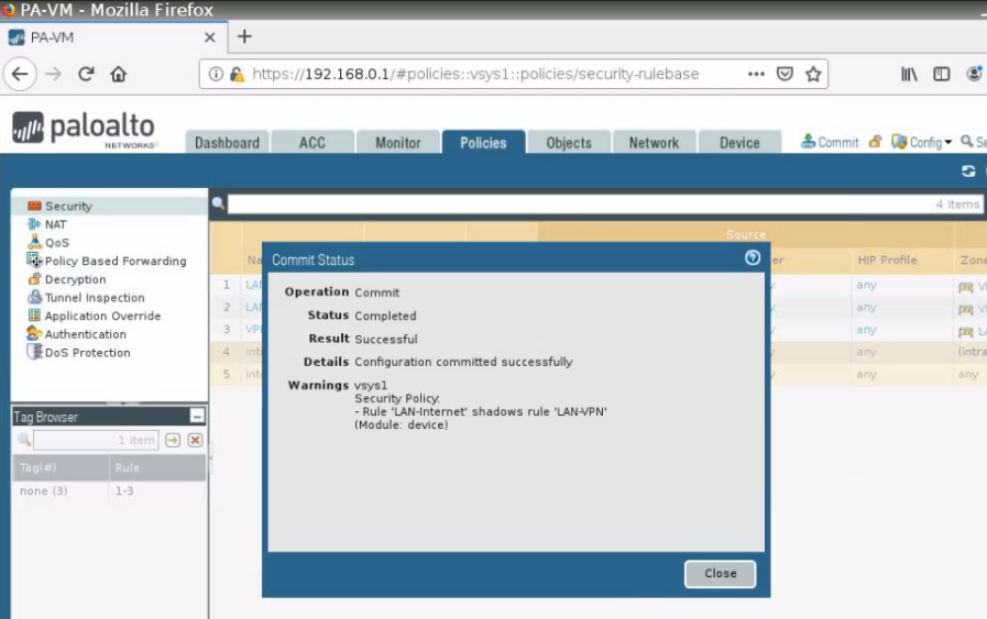
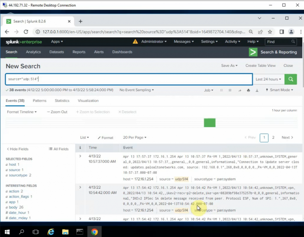
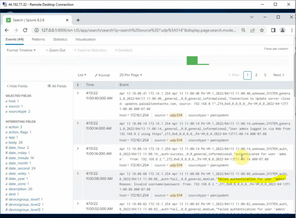
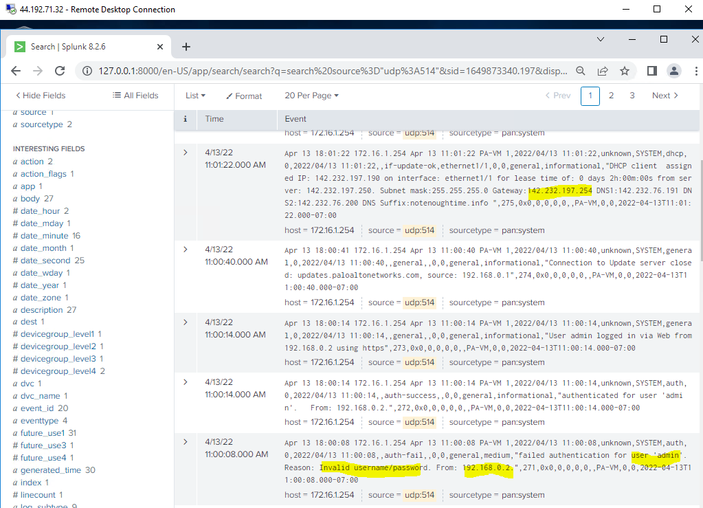
Log off and enter the wrong password on Palo Alto. Log back into Palo Alto to generate logs to send to Splunk.
We can see “failed authentication log” events have been generated on Splunk.