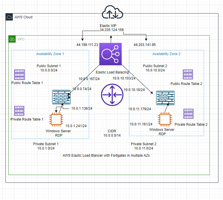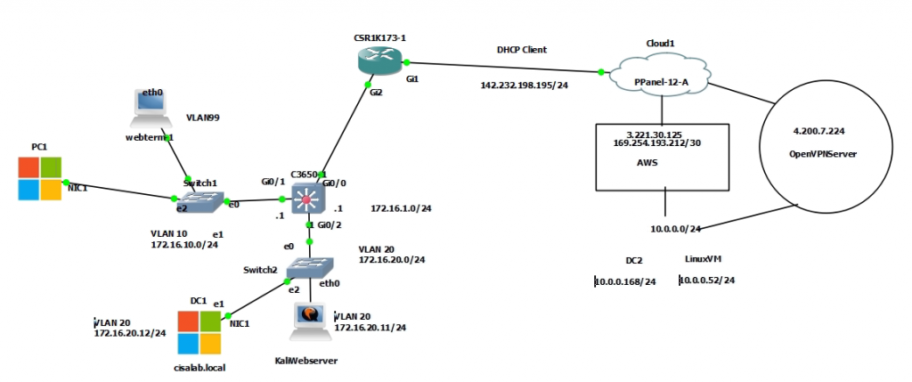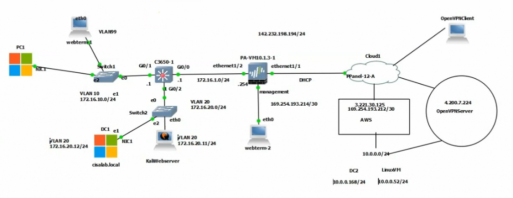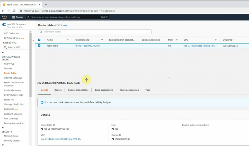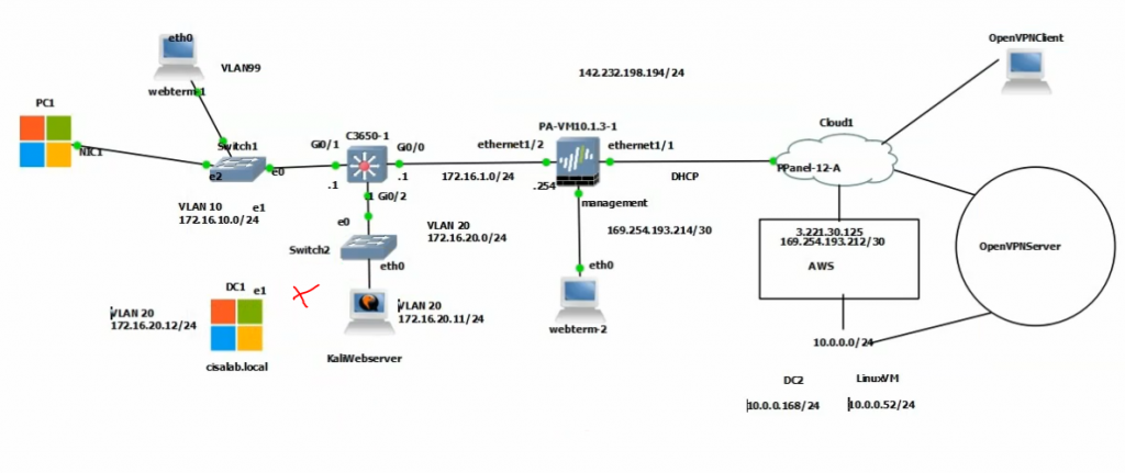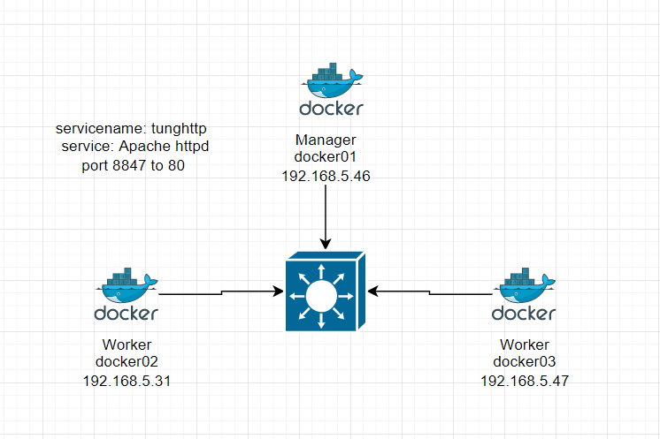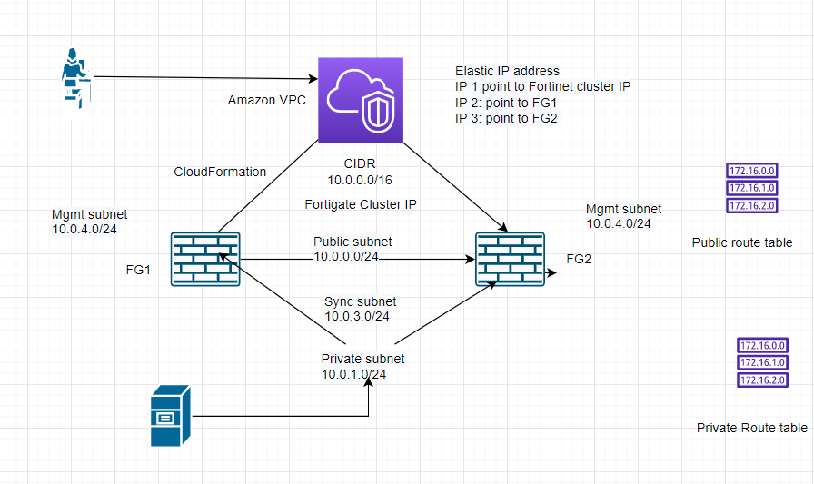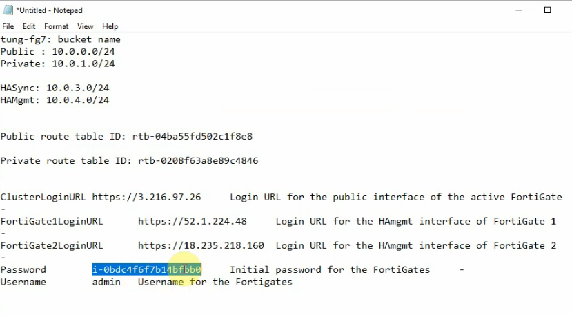
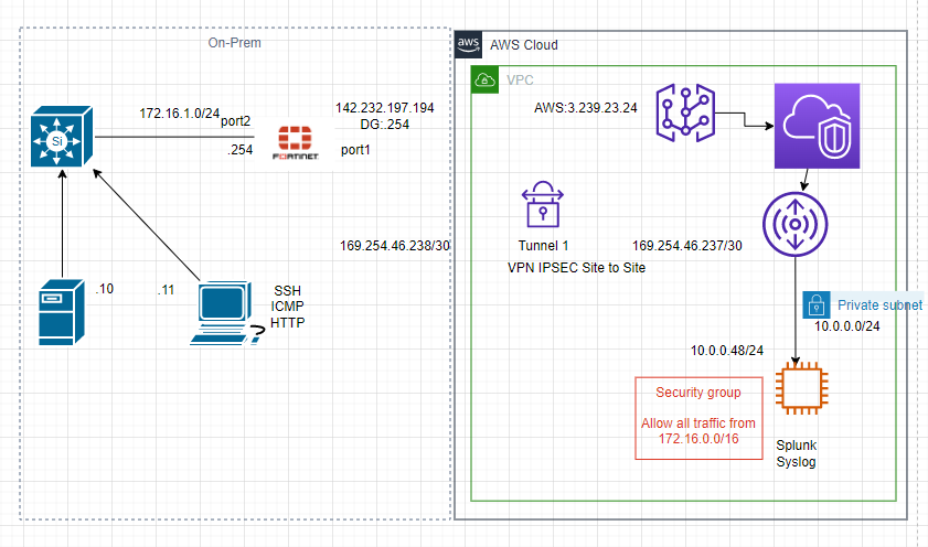
This is a diagram that I have used for this demonstration.
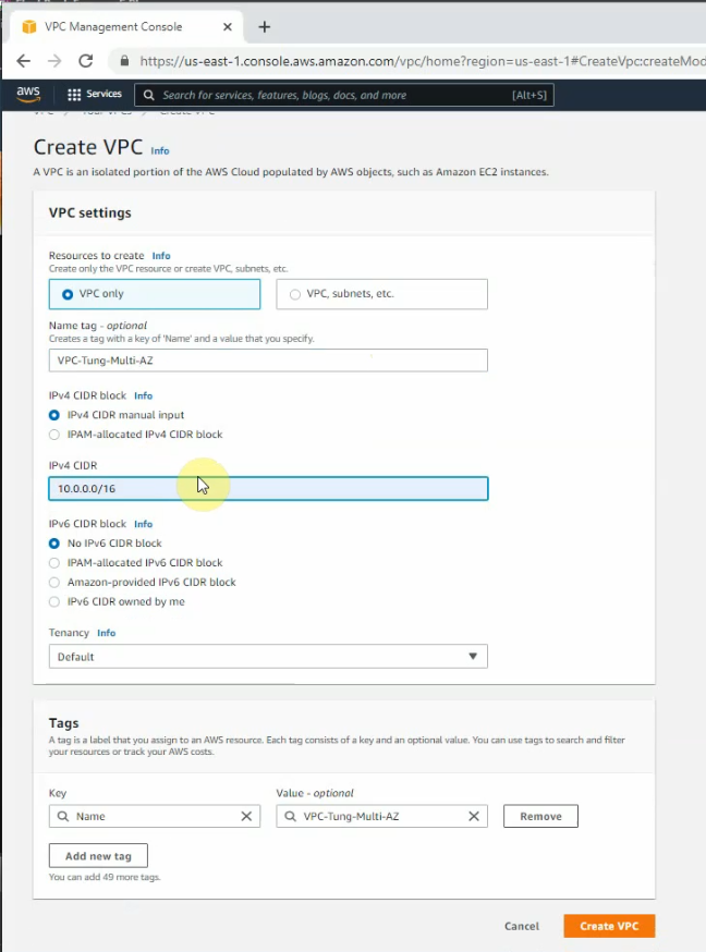
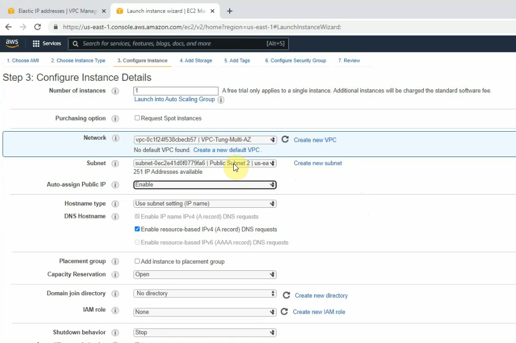
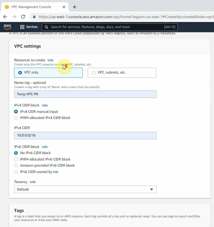
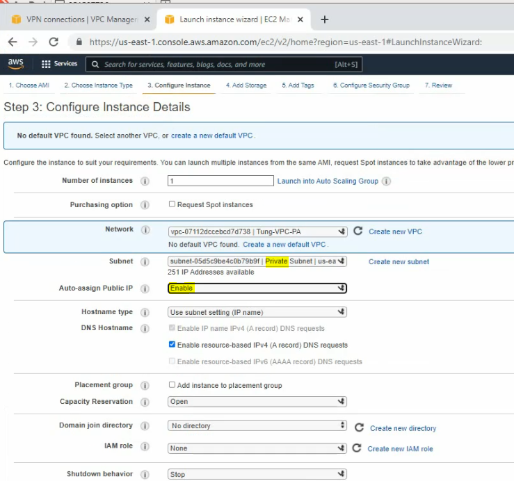
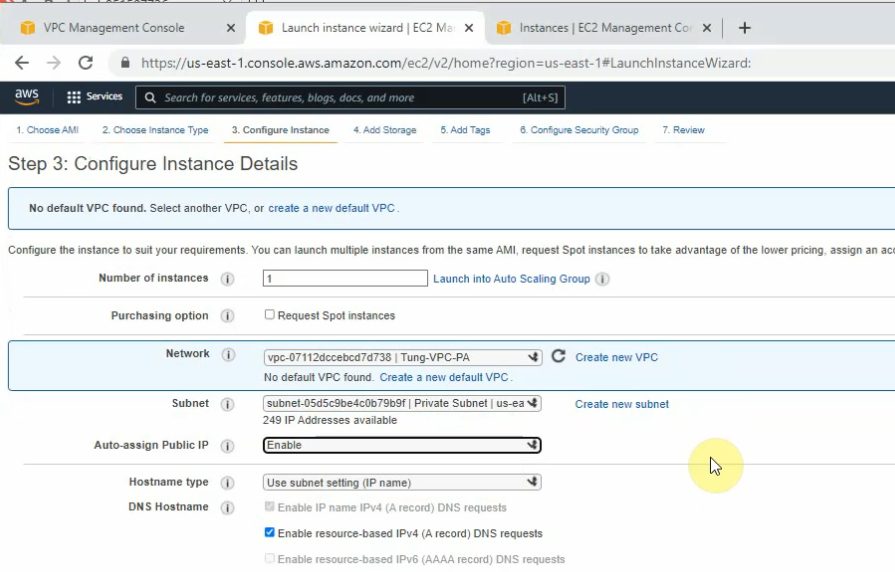
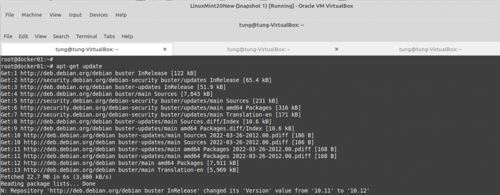
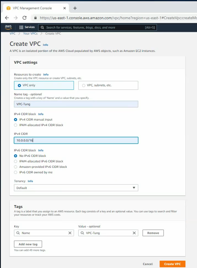
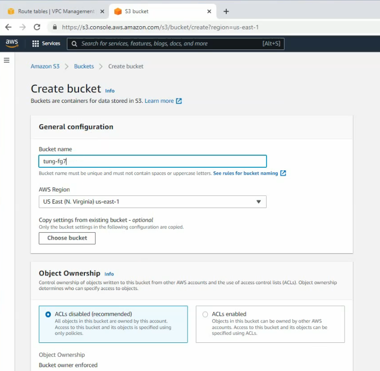
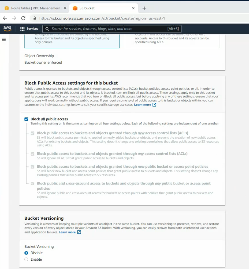
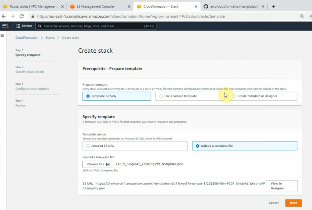
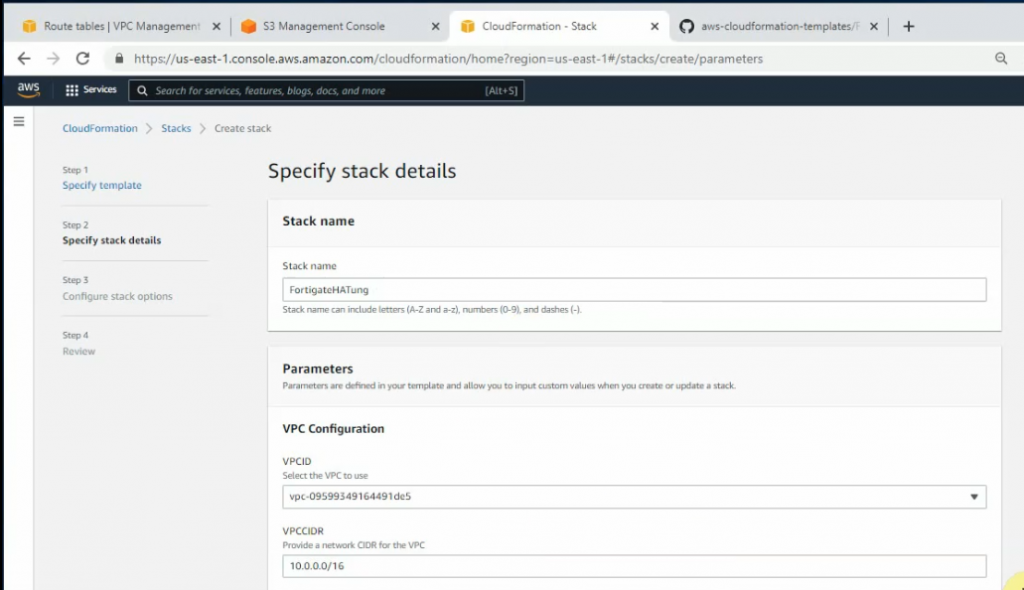
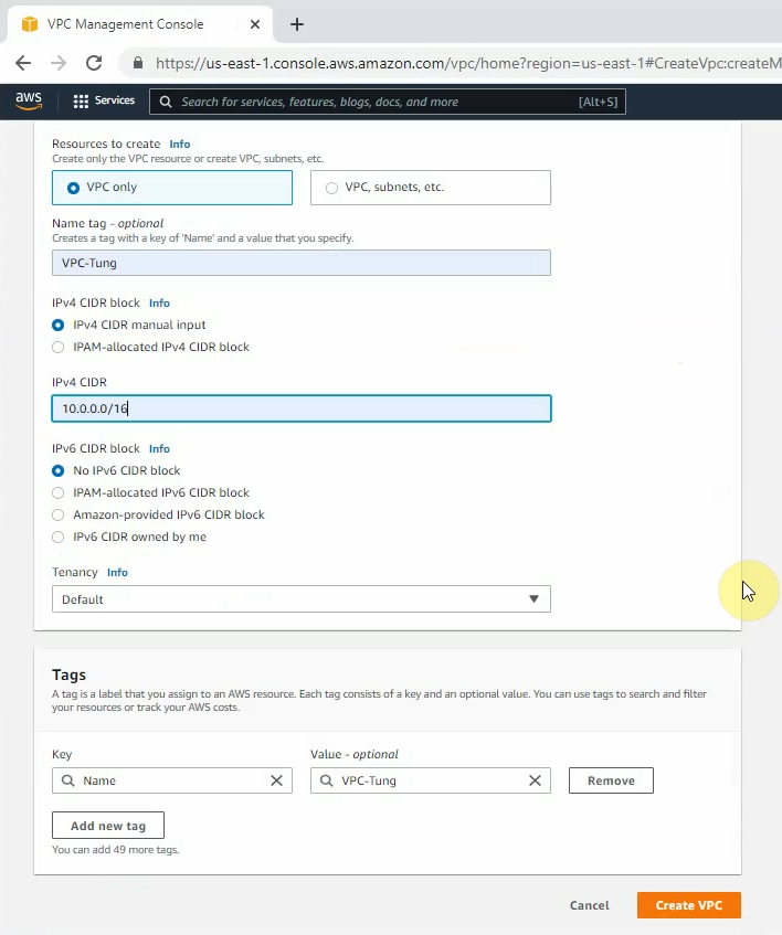
Create your VPC.
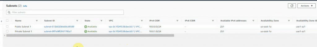
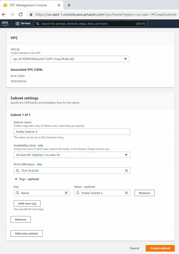
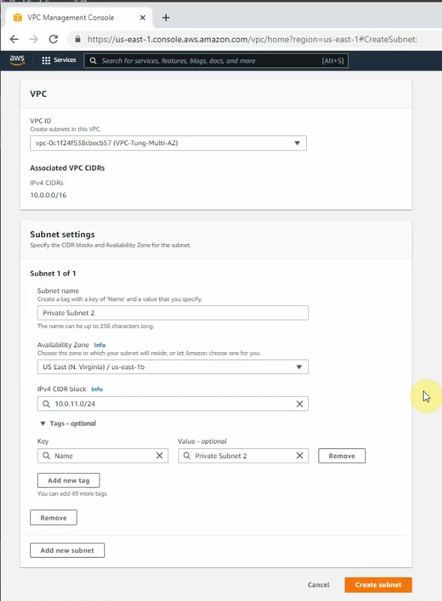
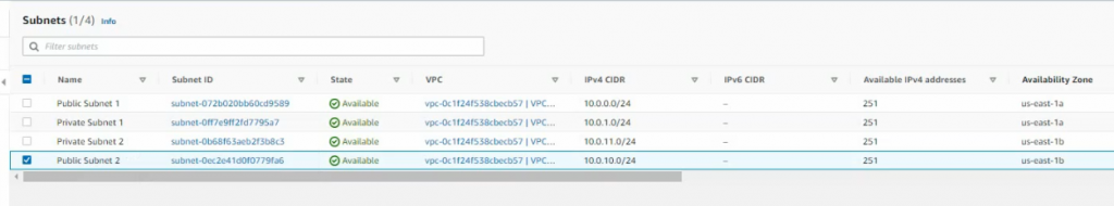
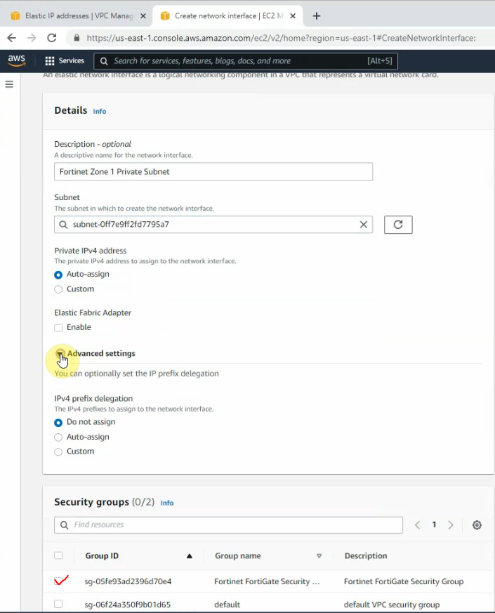
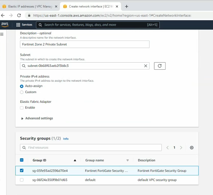
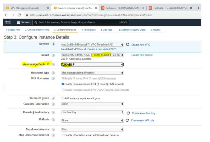
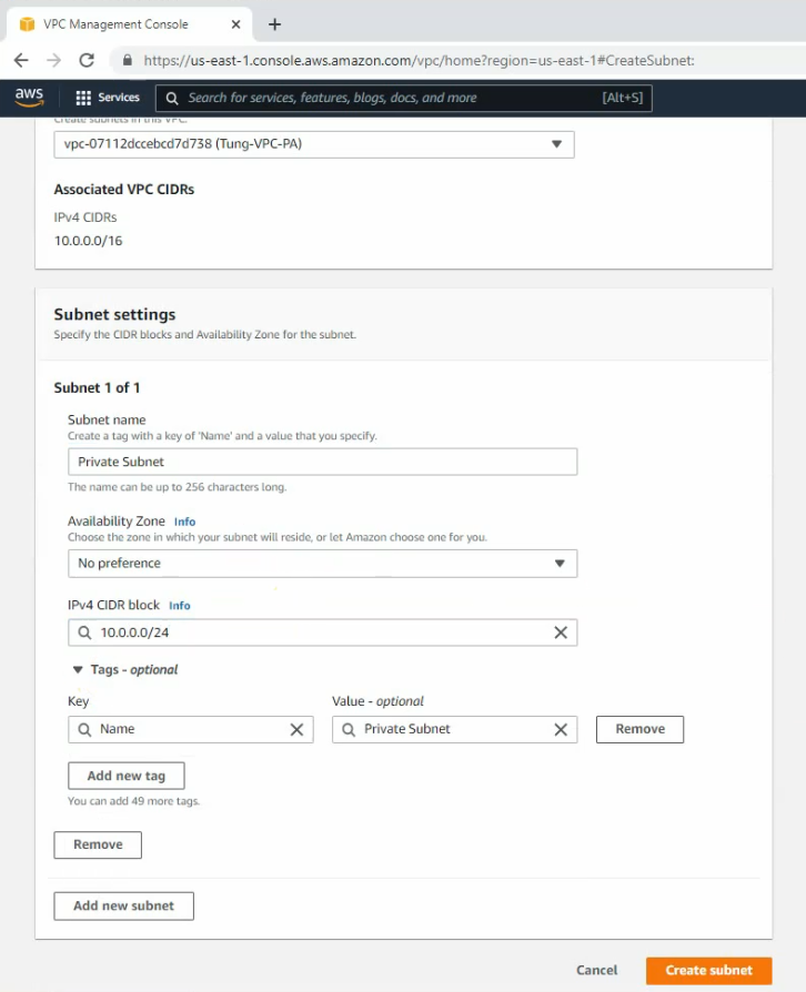
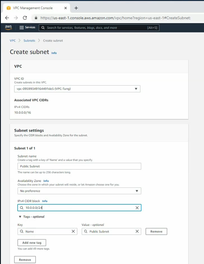
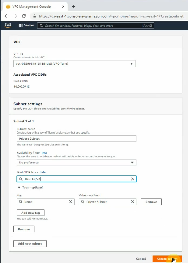
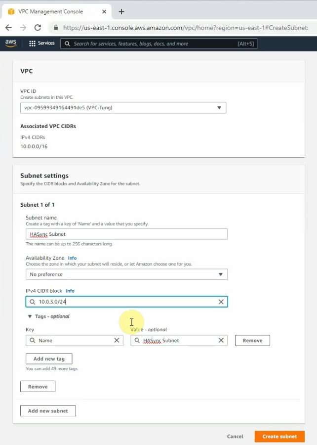
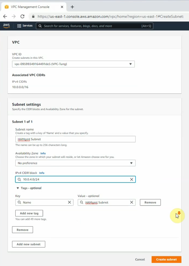
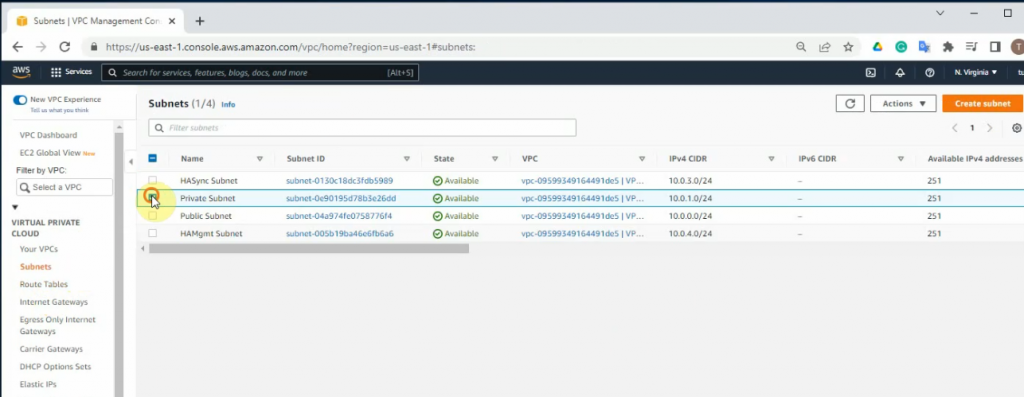
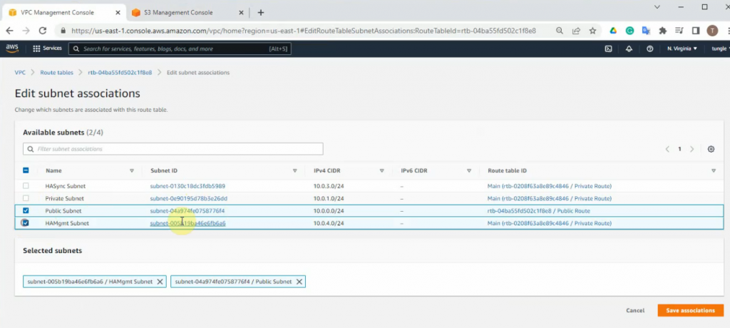
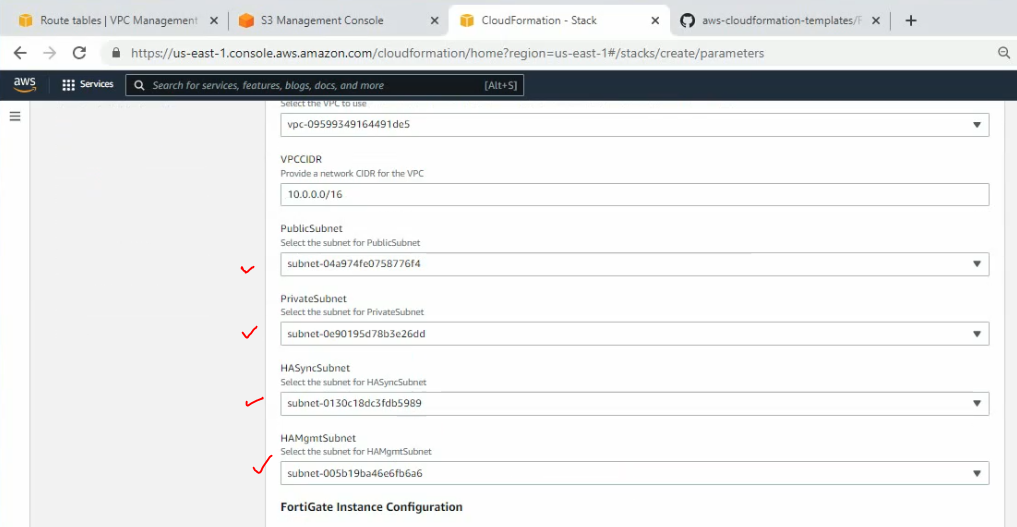
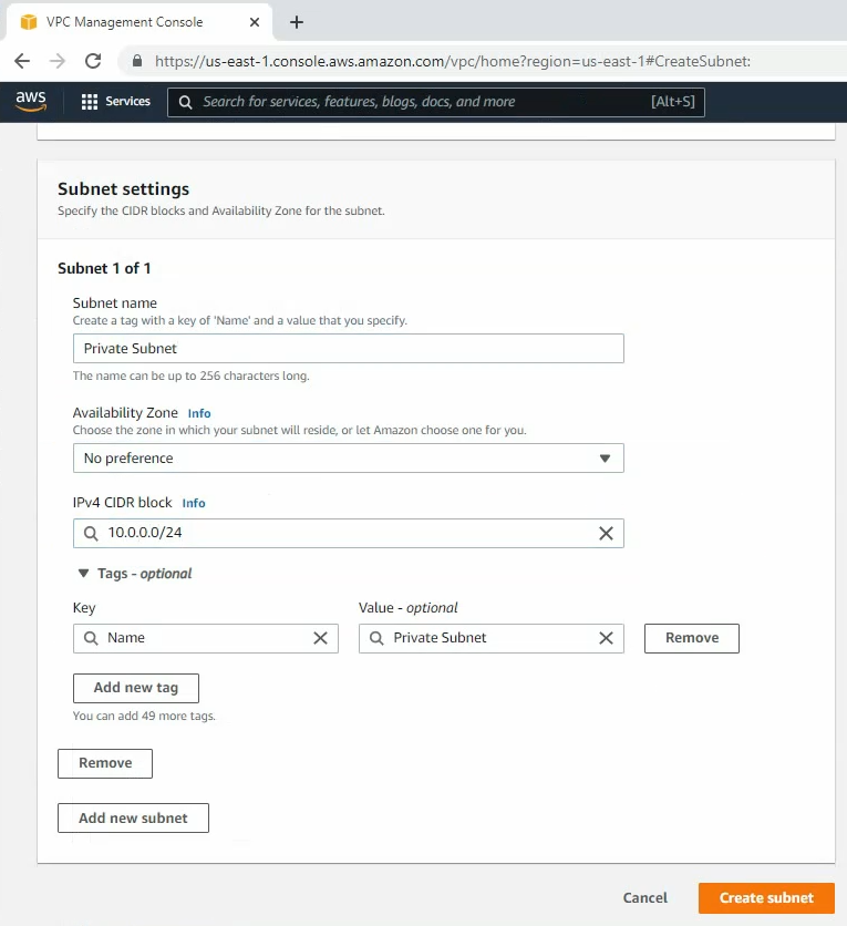
Create a private subnet.
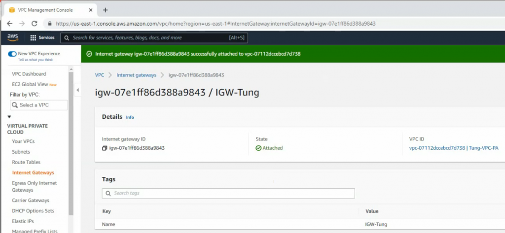
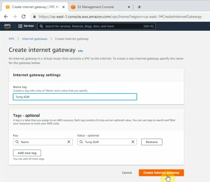
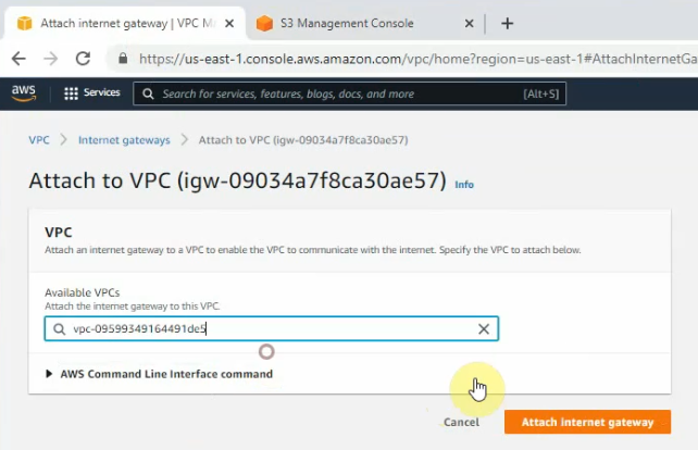
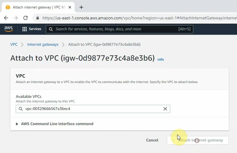
Create a new Internet Gateway and attach it to your VPC.
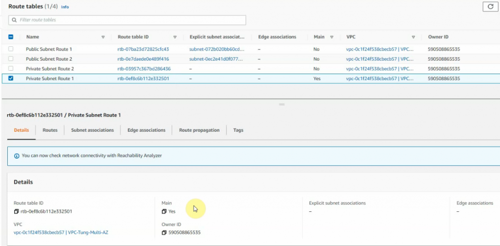
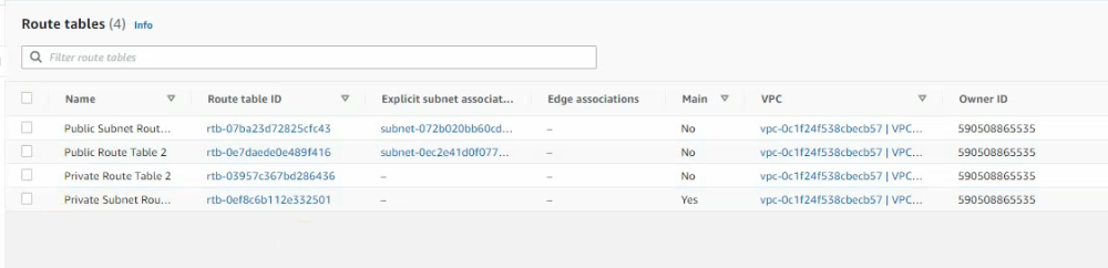
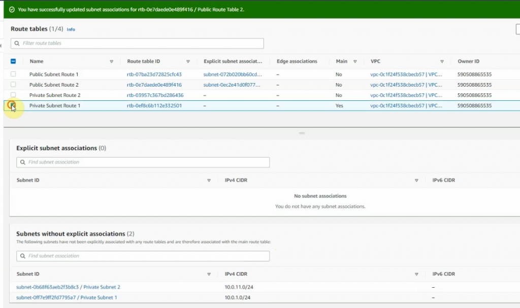
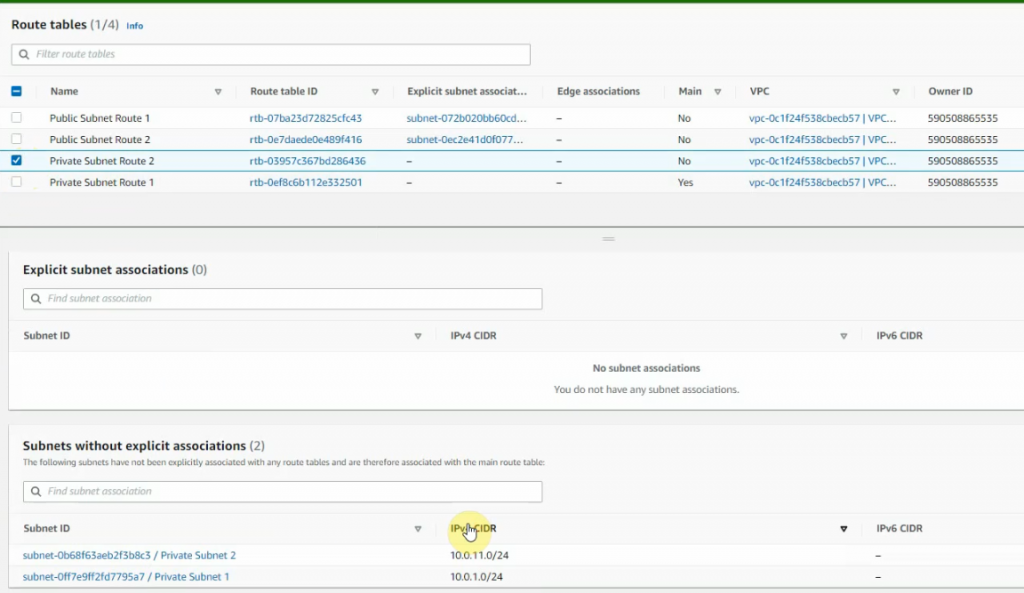
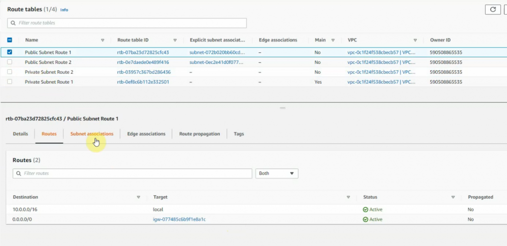
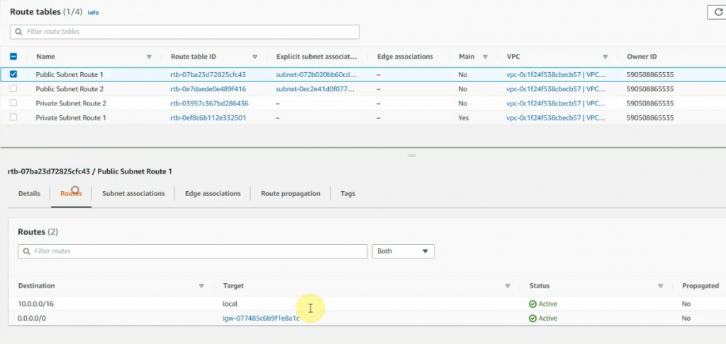
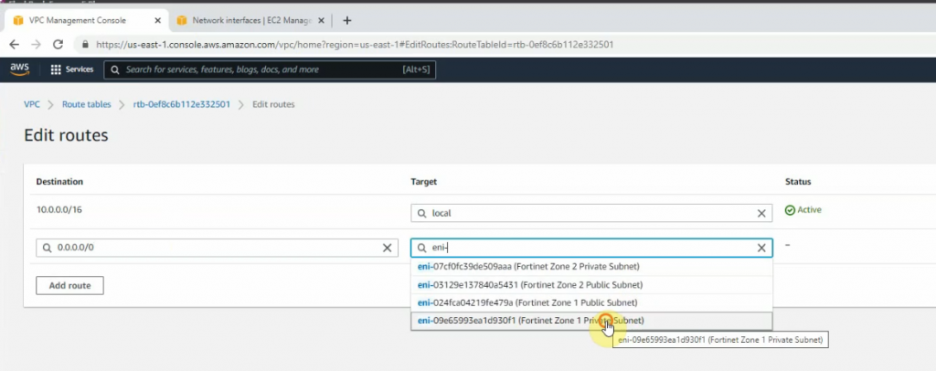
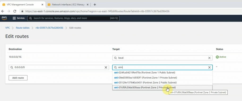
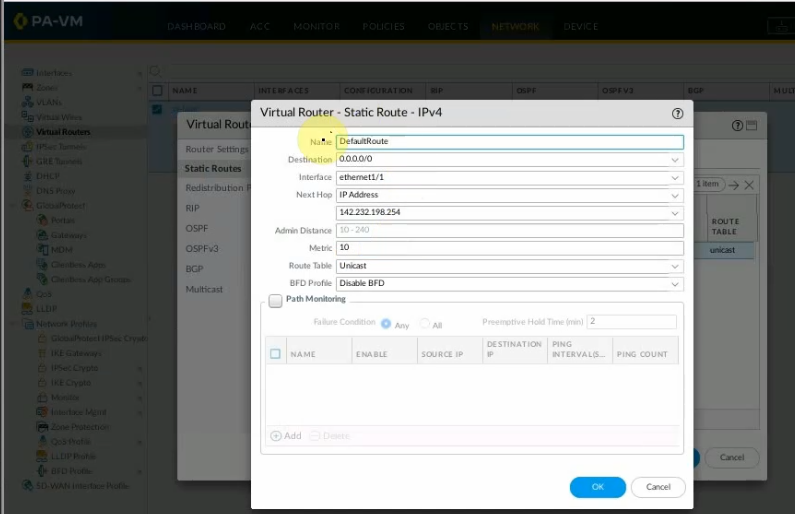
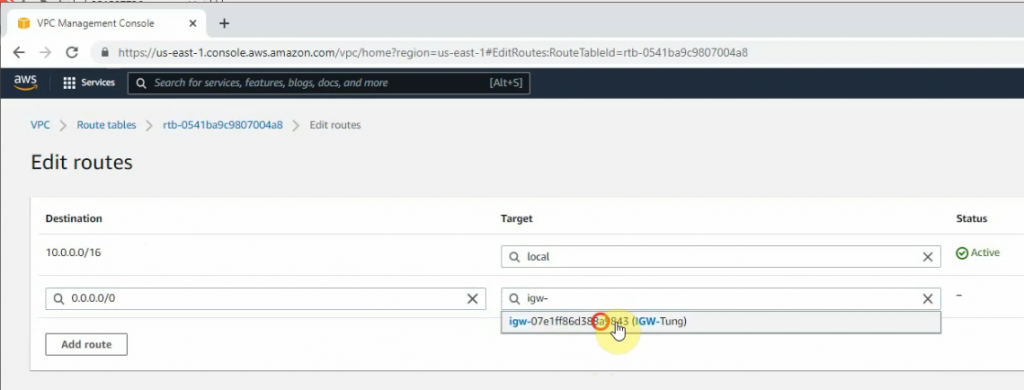
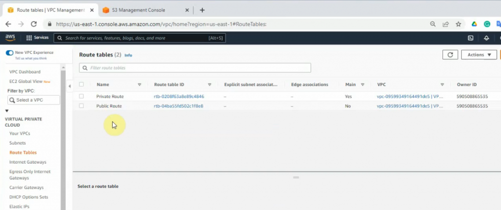
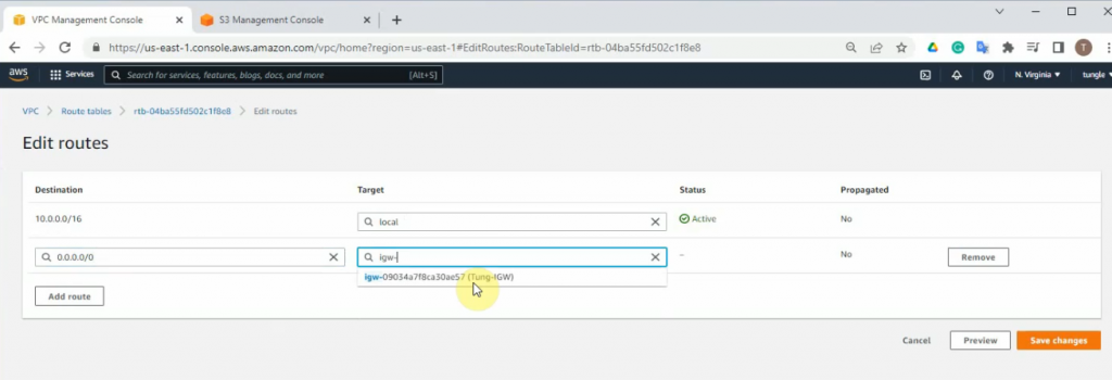
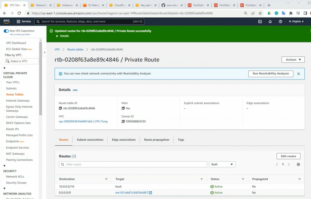
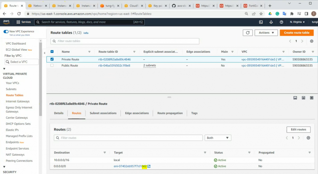
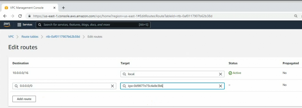
Create a new route to 0.0.0.0/0 to your Internet gateway.
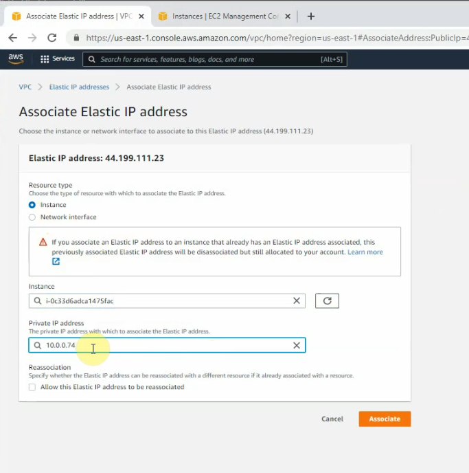
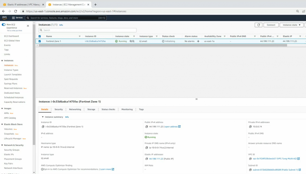
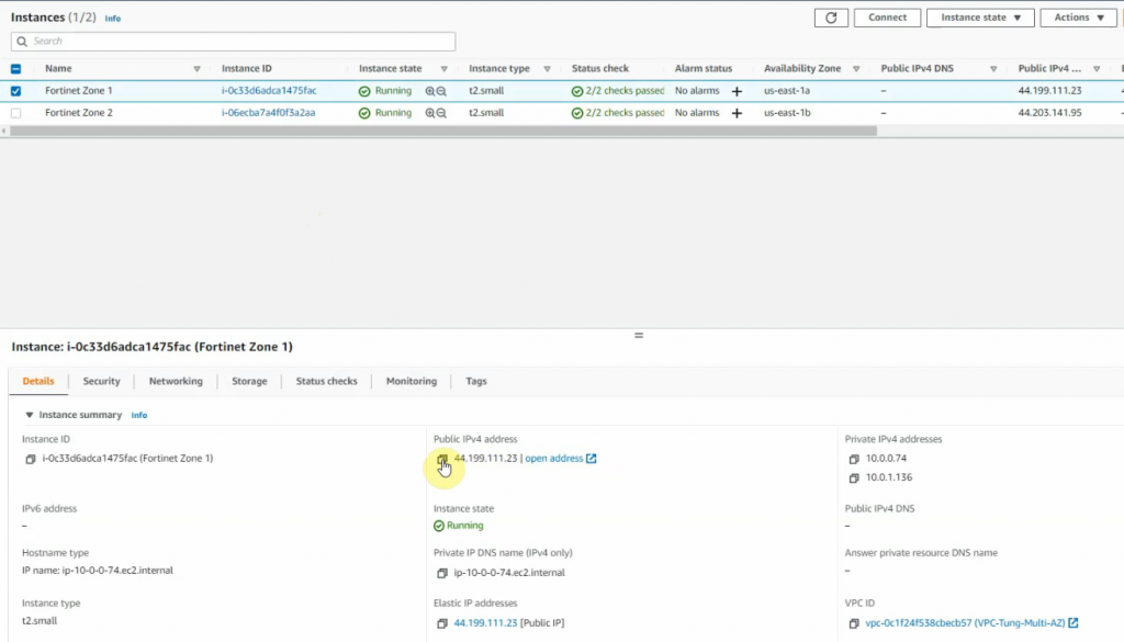
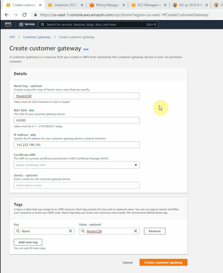
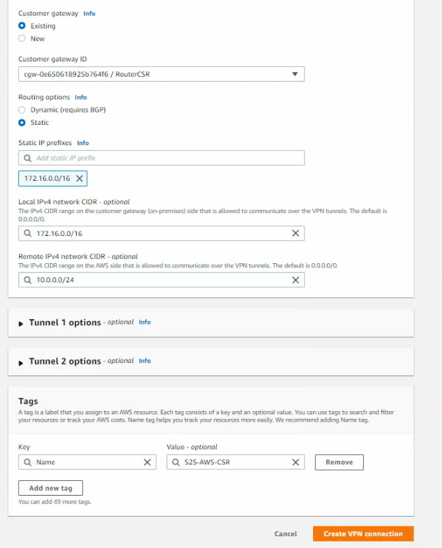
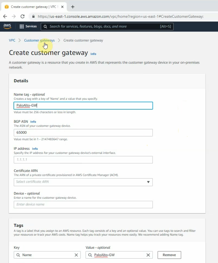
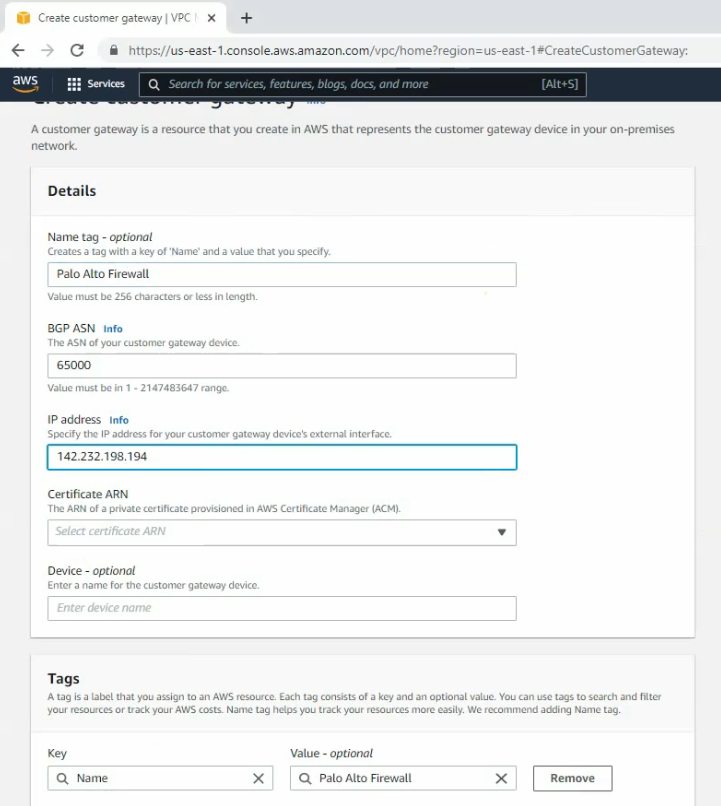
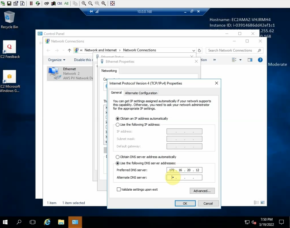
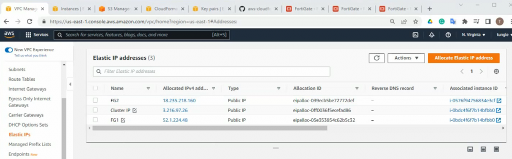
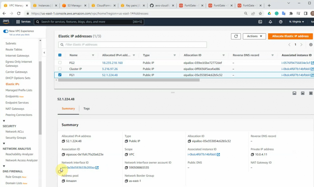
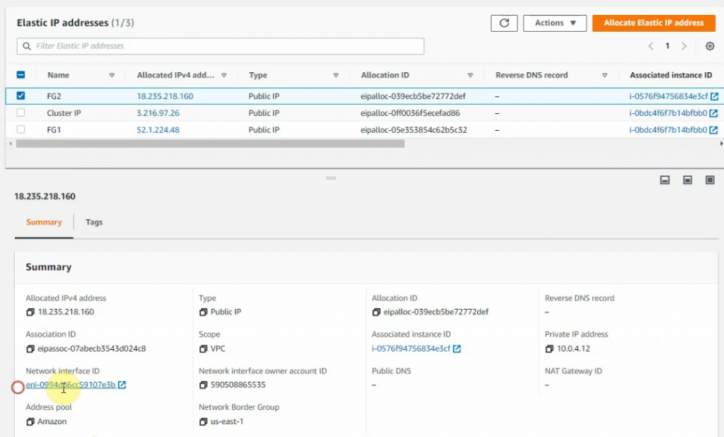
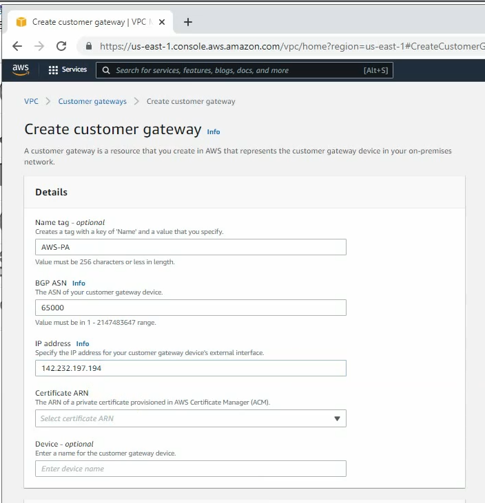
Create a new Customer gateway with the public IP address of FortiGate.
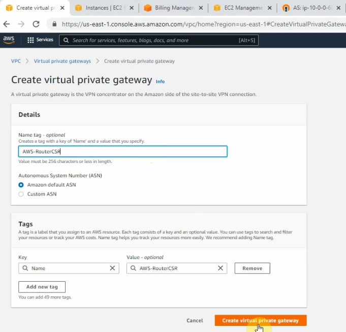
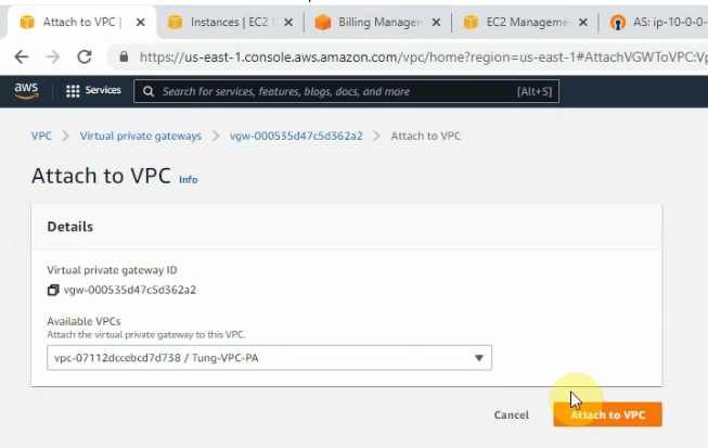
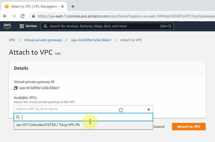
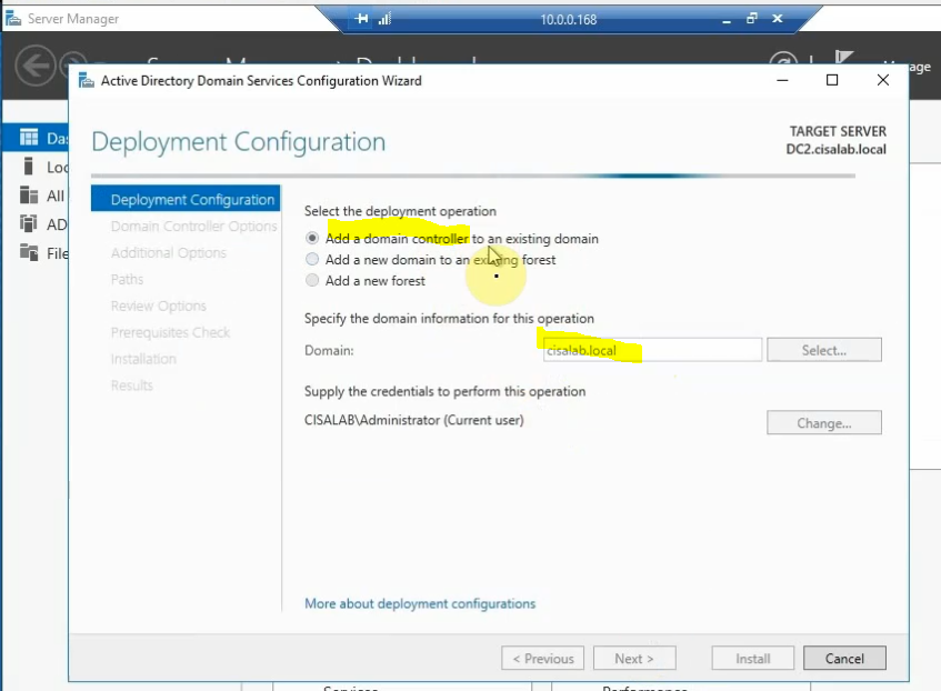
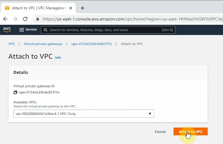
Create a new Virtual Private Gateway and attach it to your VPC.
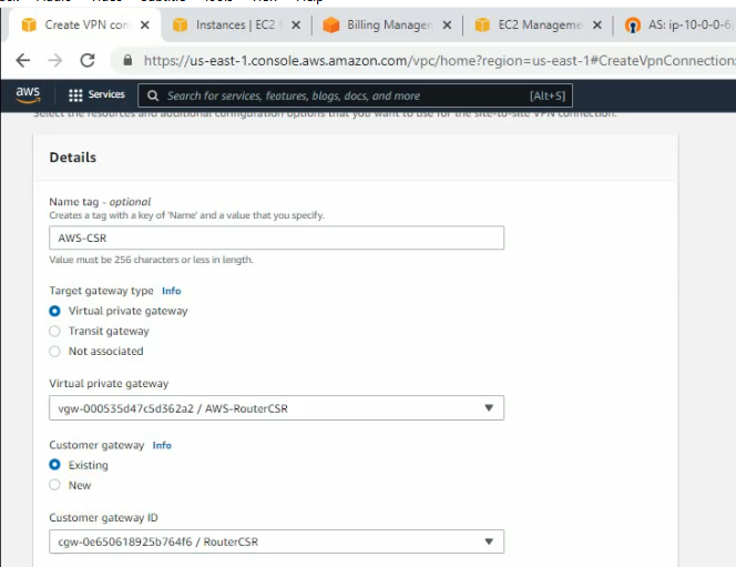
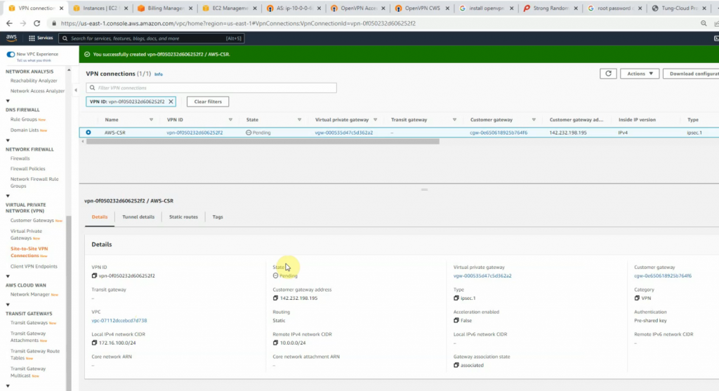
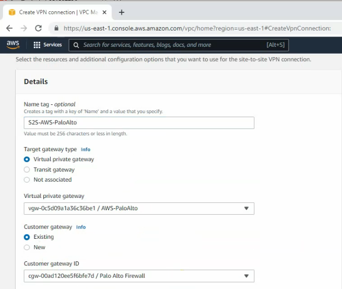
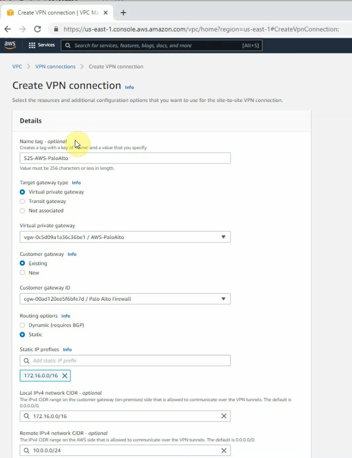
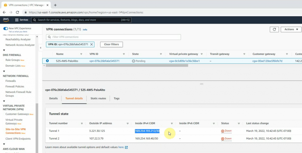
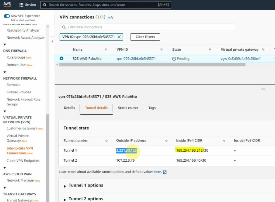
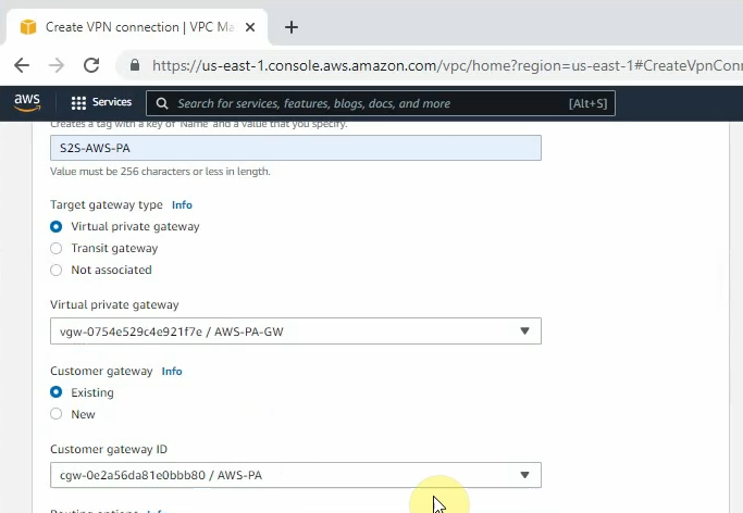
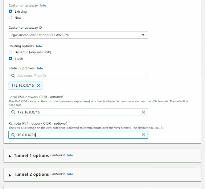
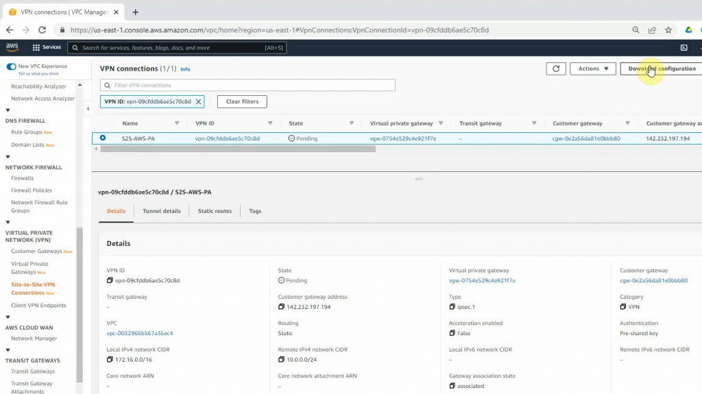
Create a new VPN site-to-site.
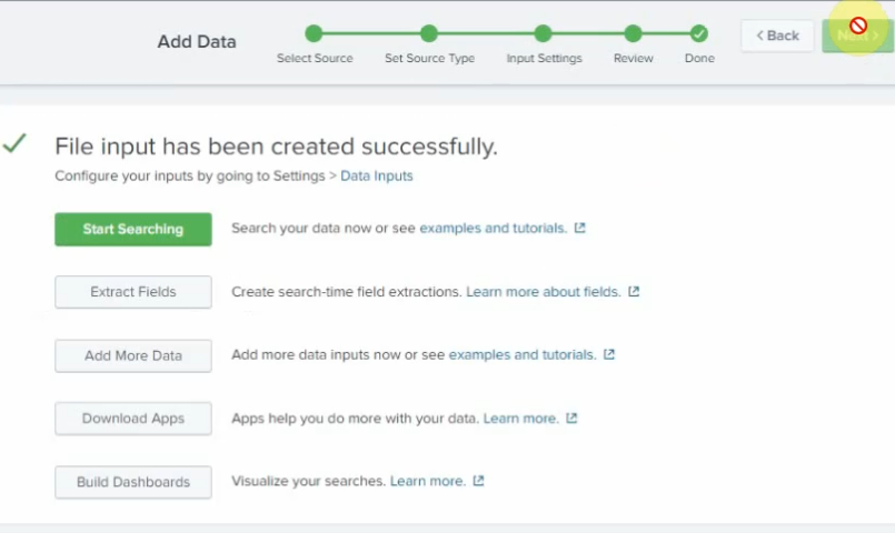
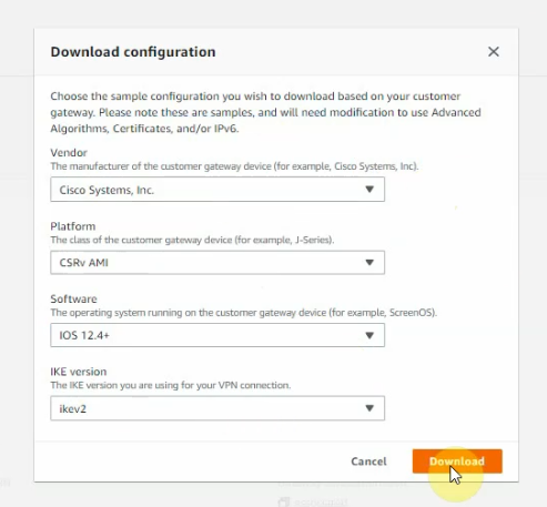
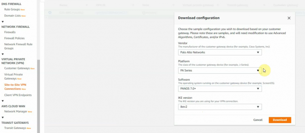
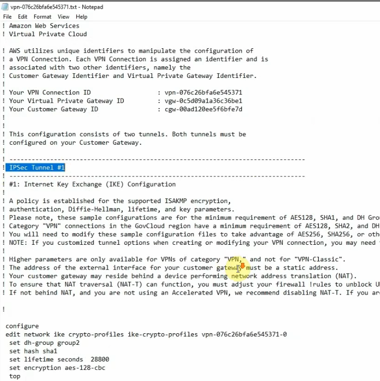
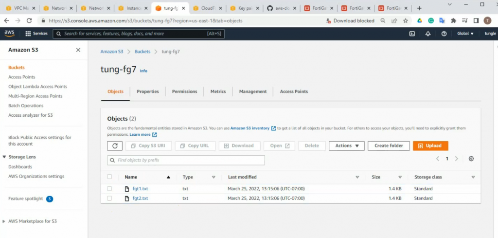
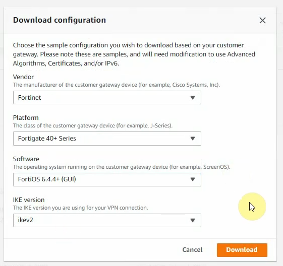
Click Download Configuration to configure on your FortiGate.
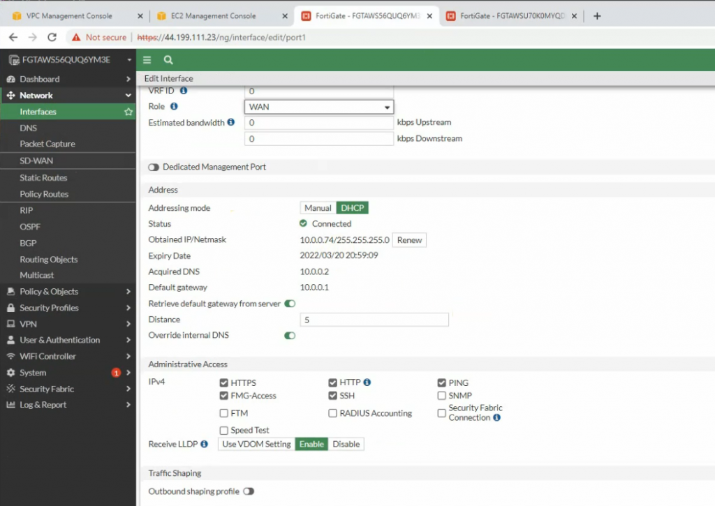
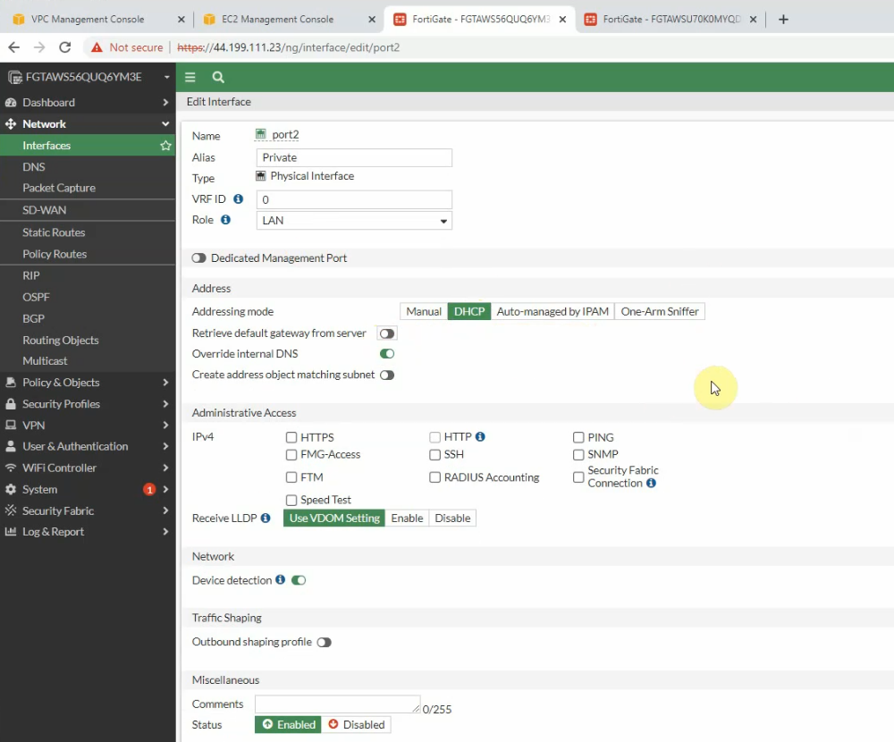
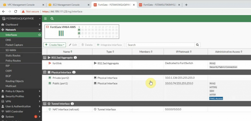
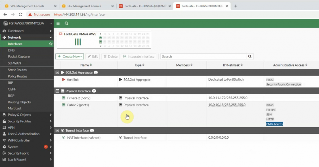
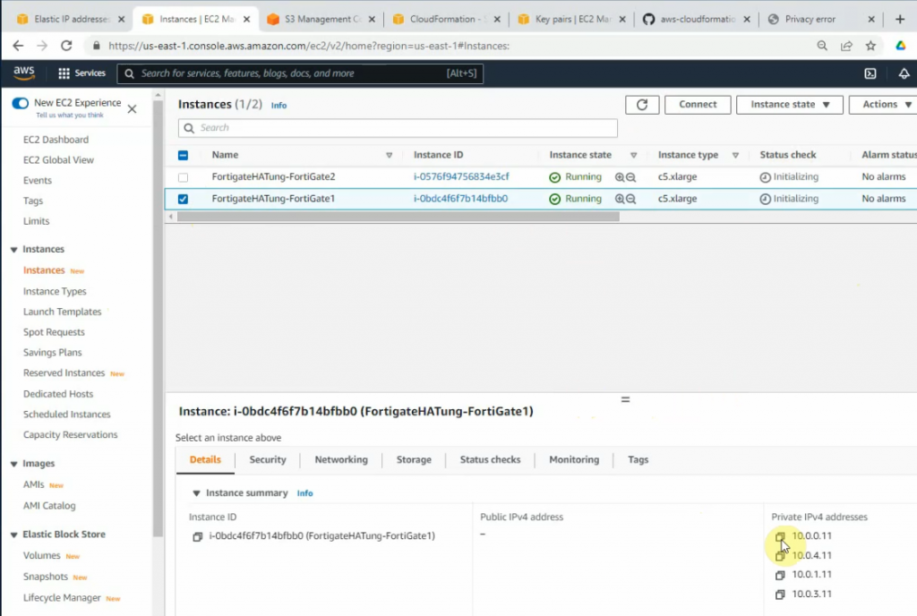
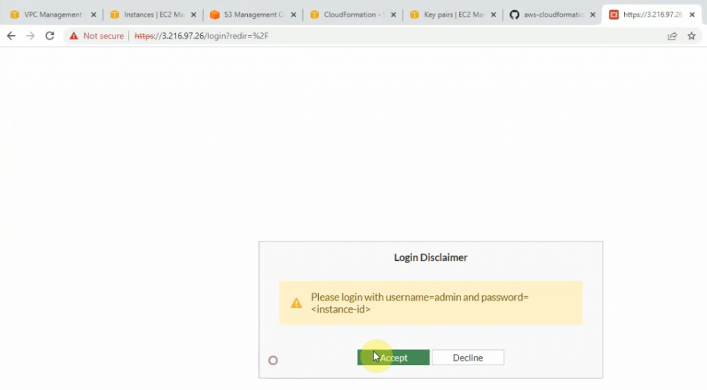
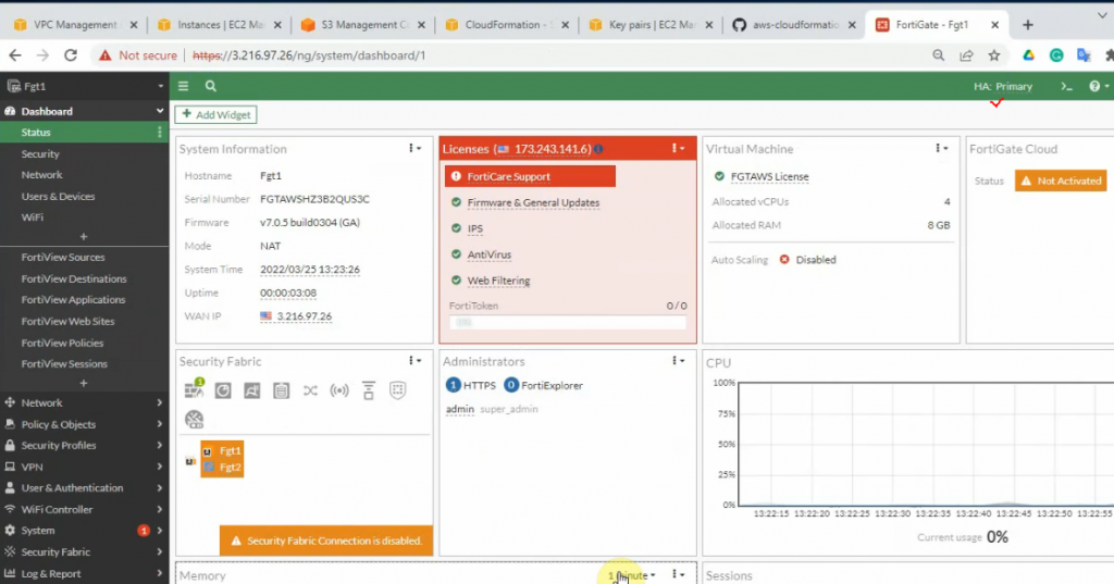
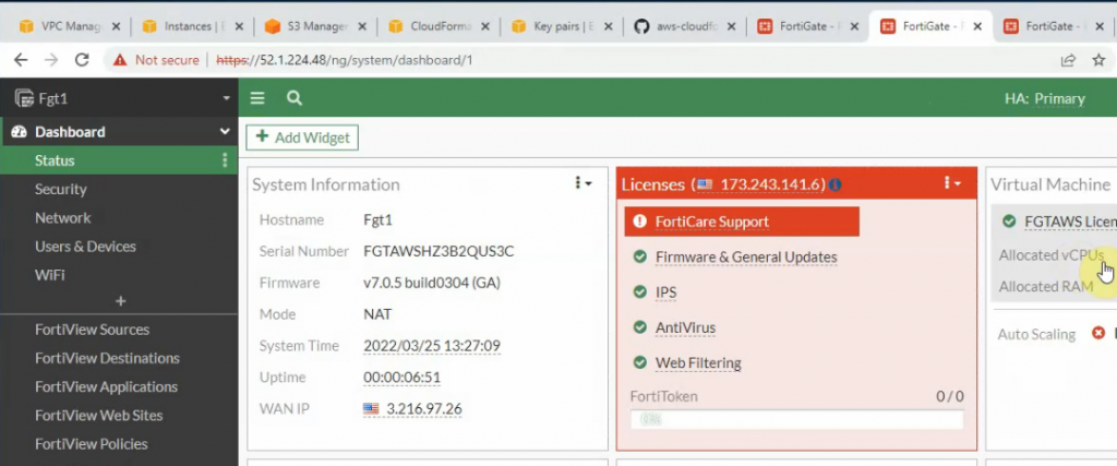
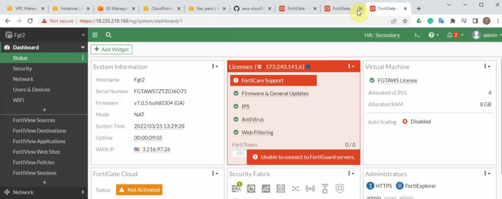
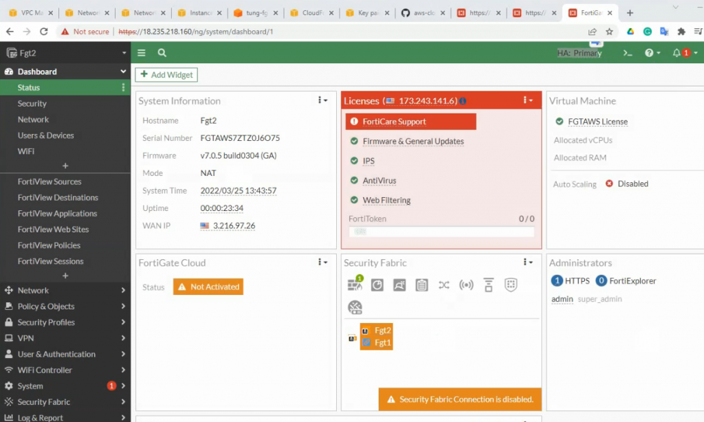
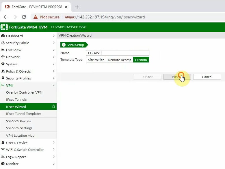
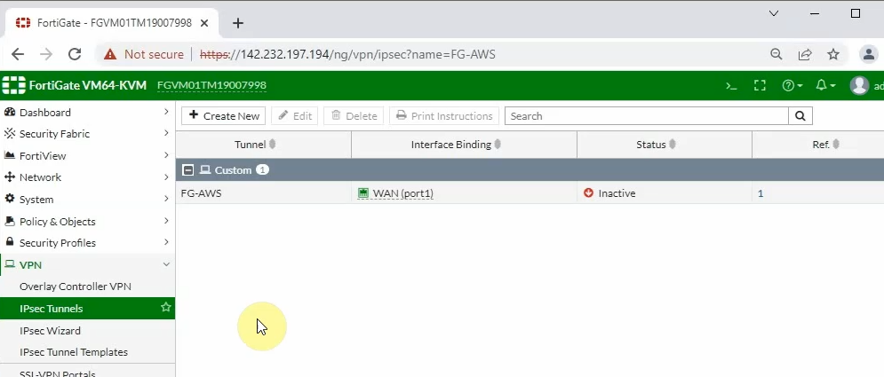
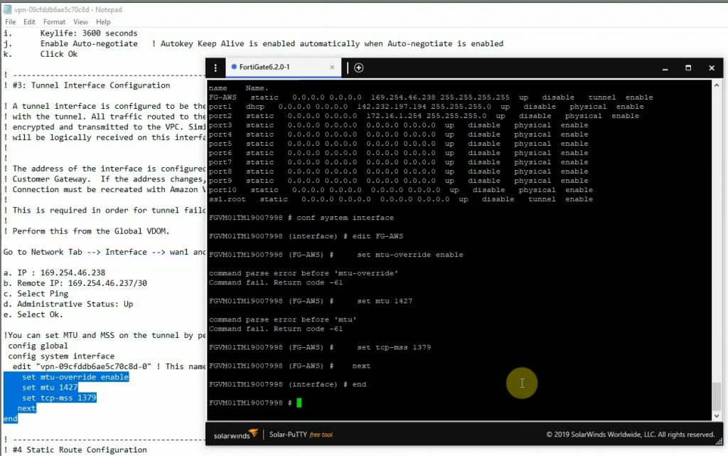
Log into FortiGate.
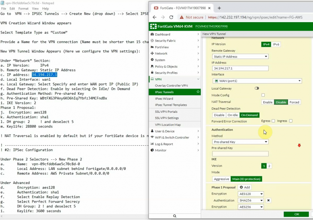
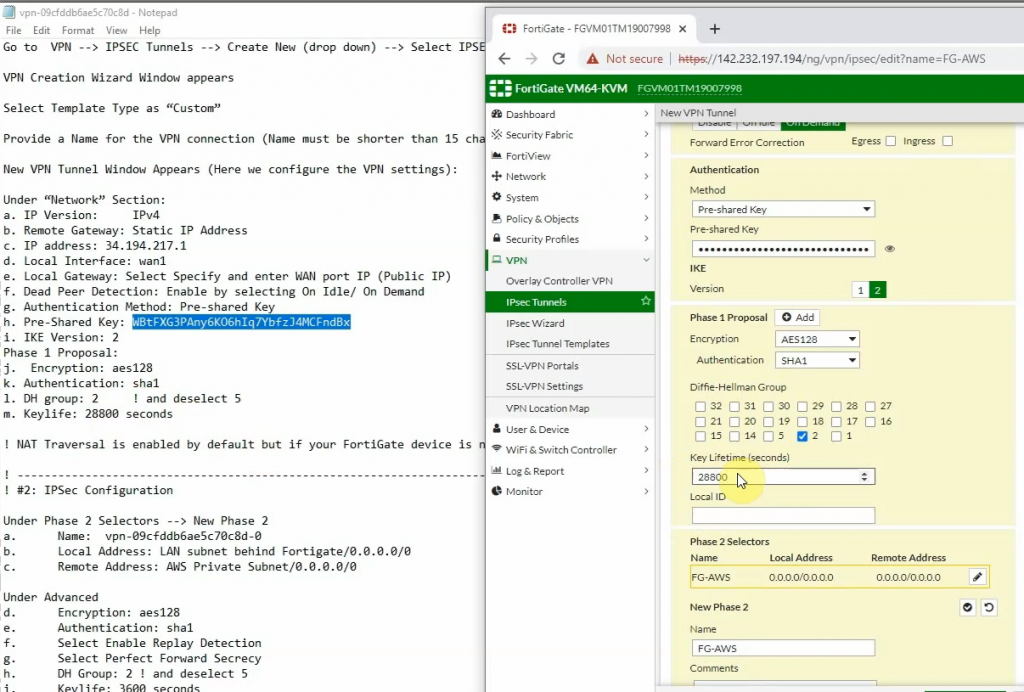
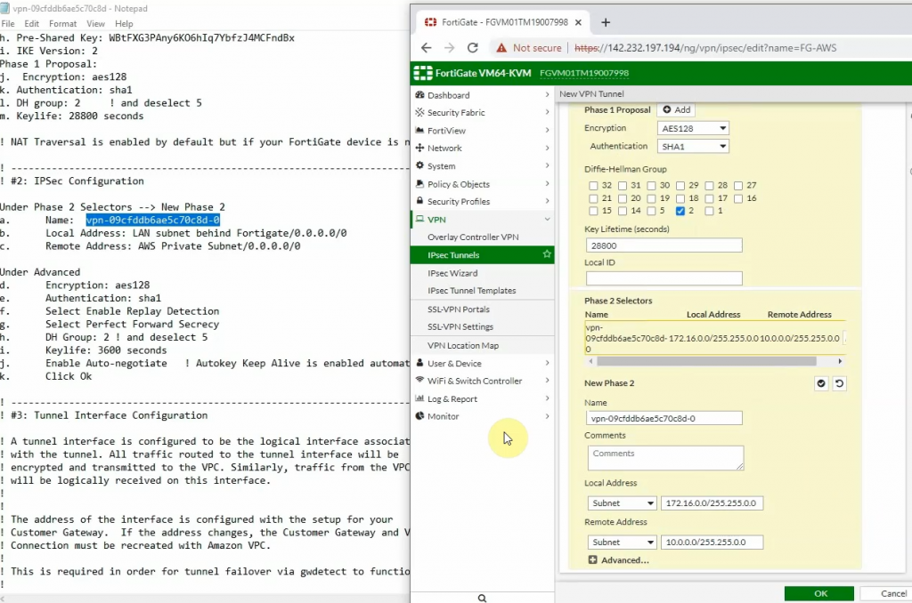
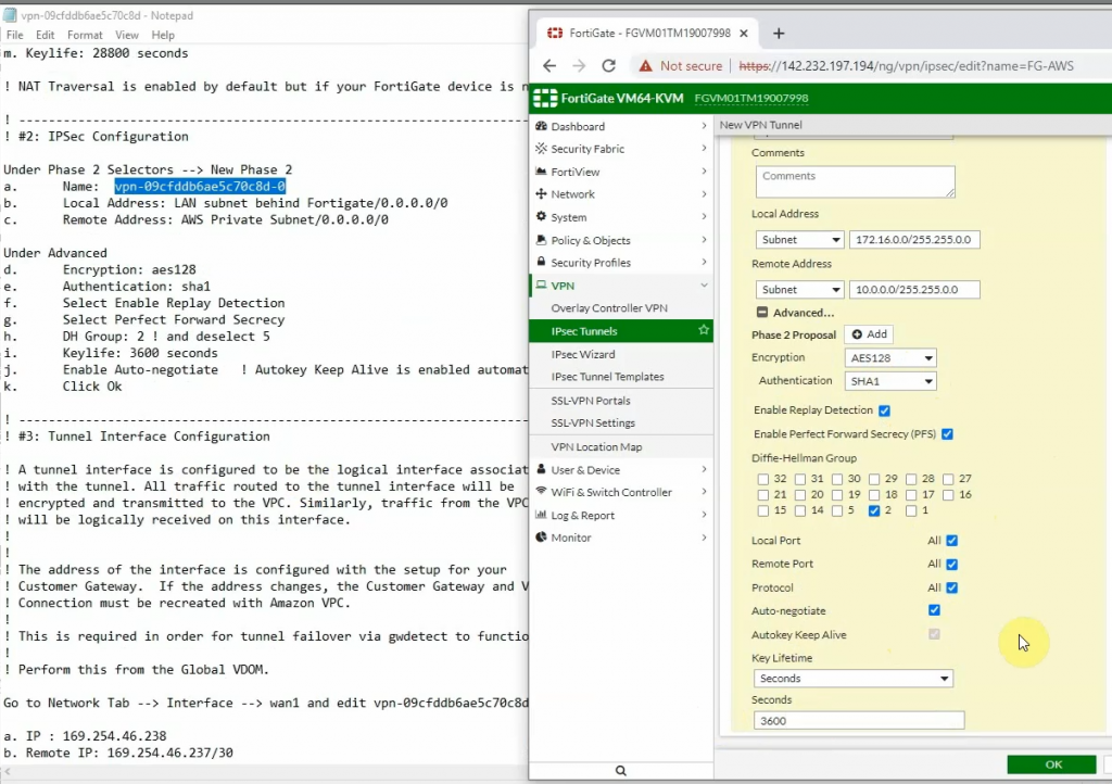
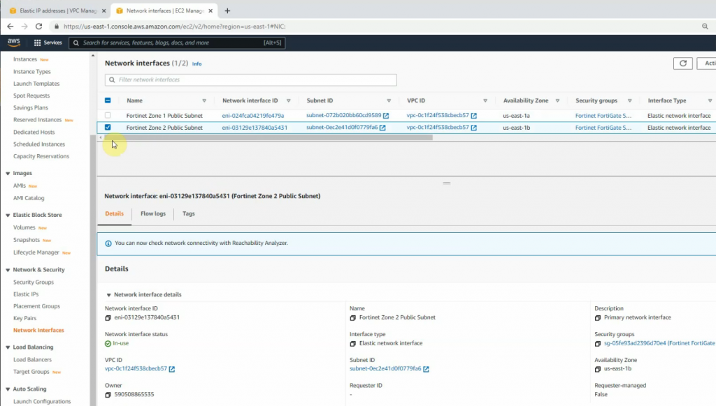
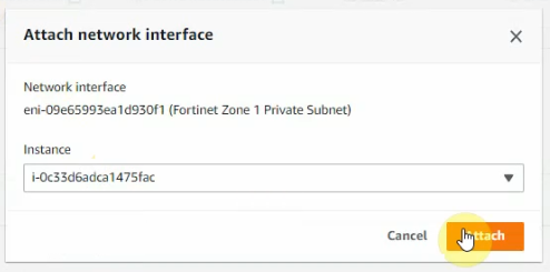
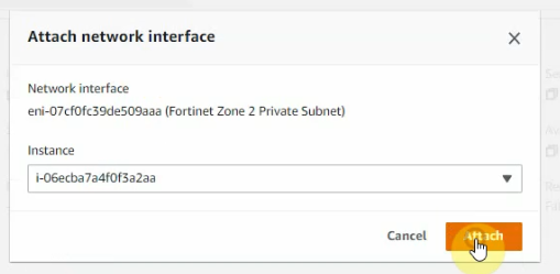
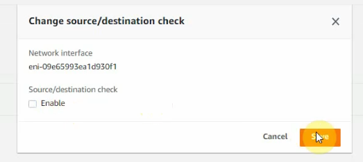
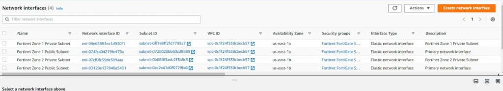
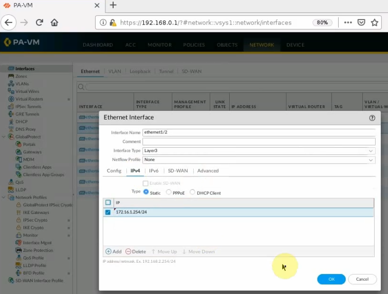
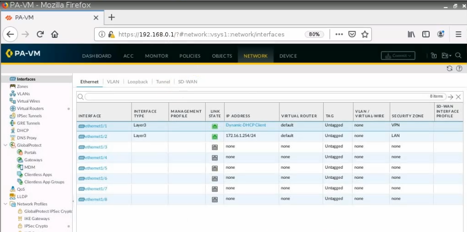
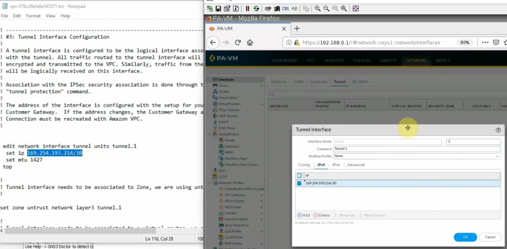
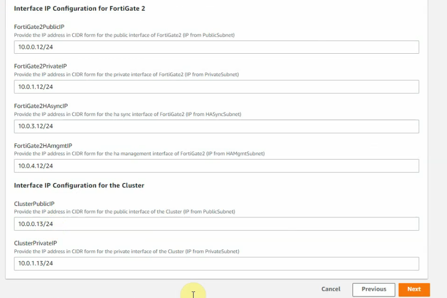
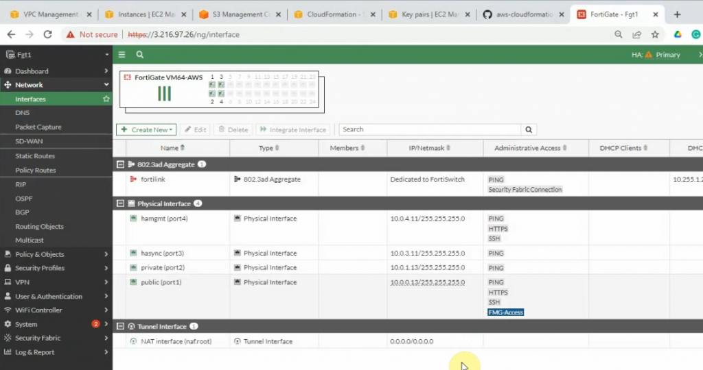
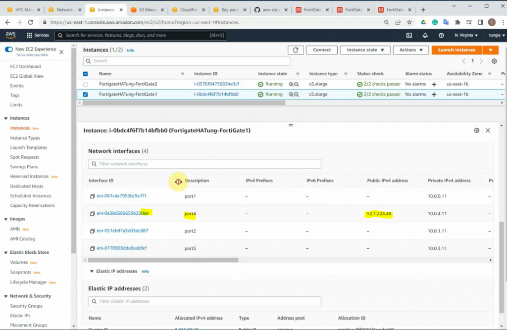
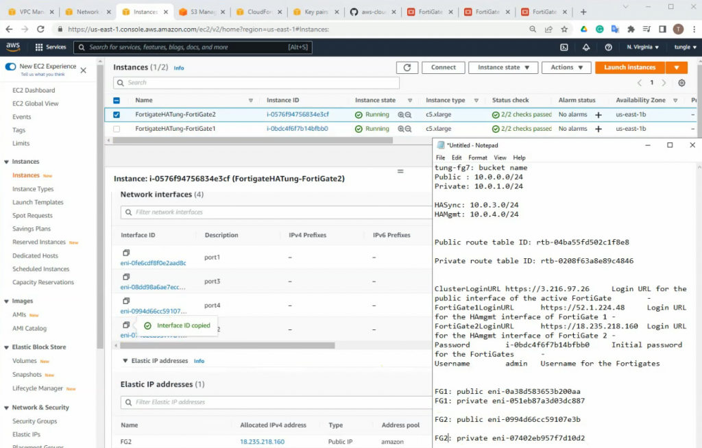
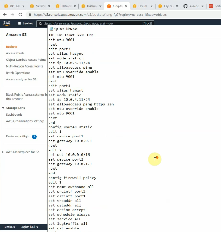
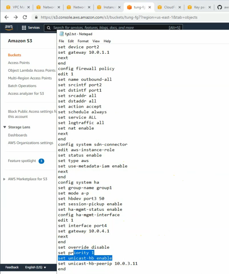
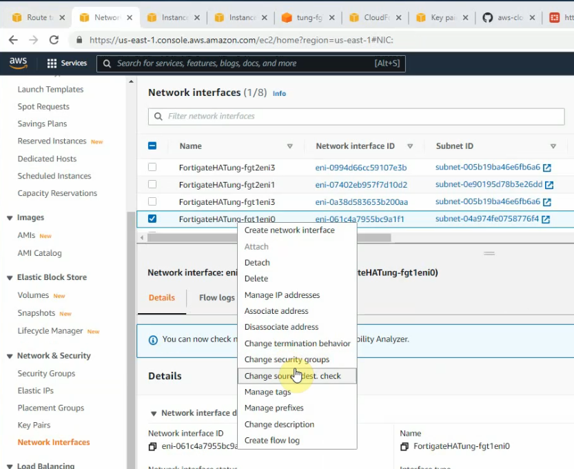
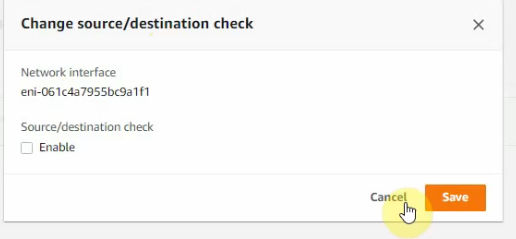
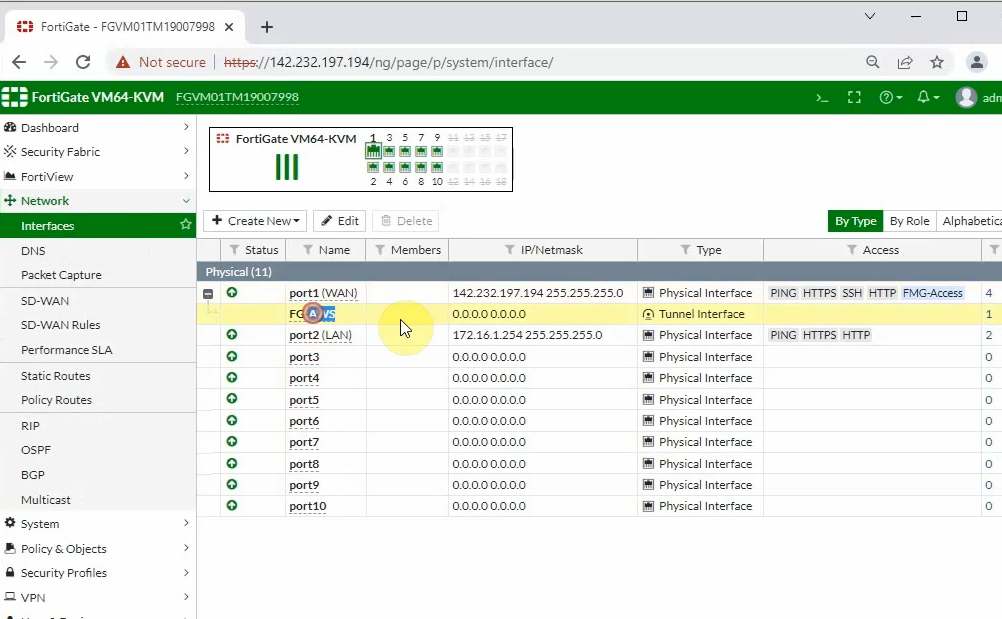
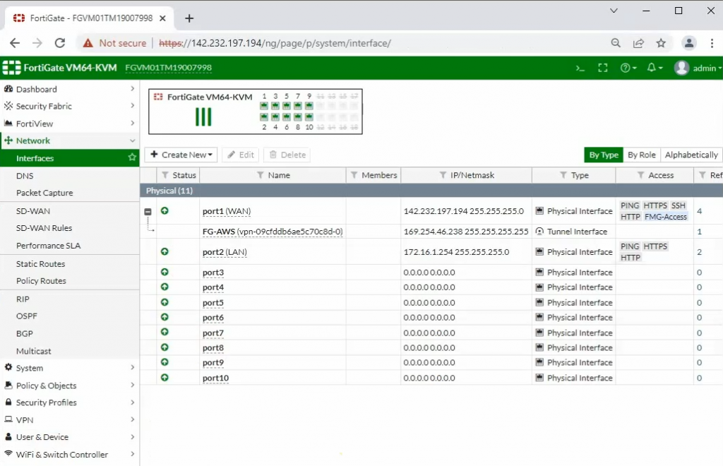
Interfaces.
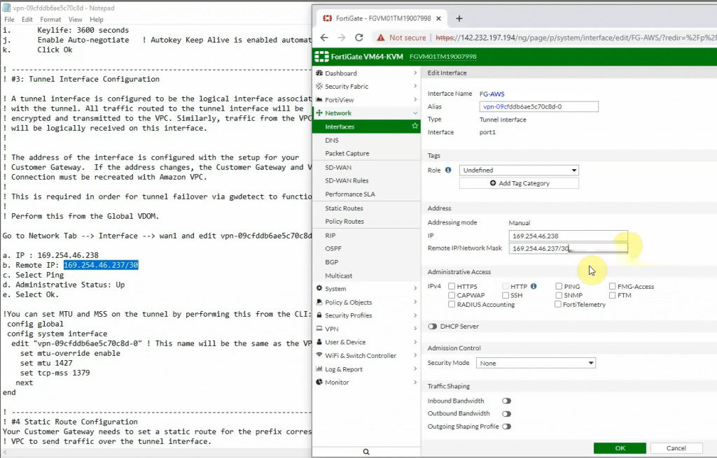
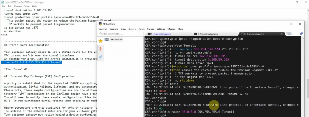
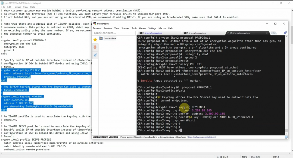
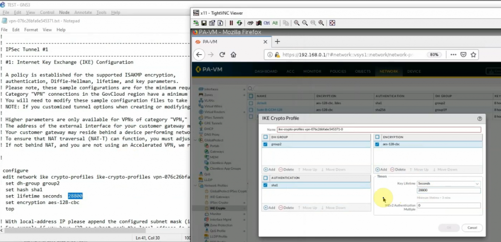
Copies these commands and pastes them into FortiGate. Notes the set “mtu 1427” and set “mtu-override enable” does not available on FortiGate 6.2
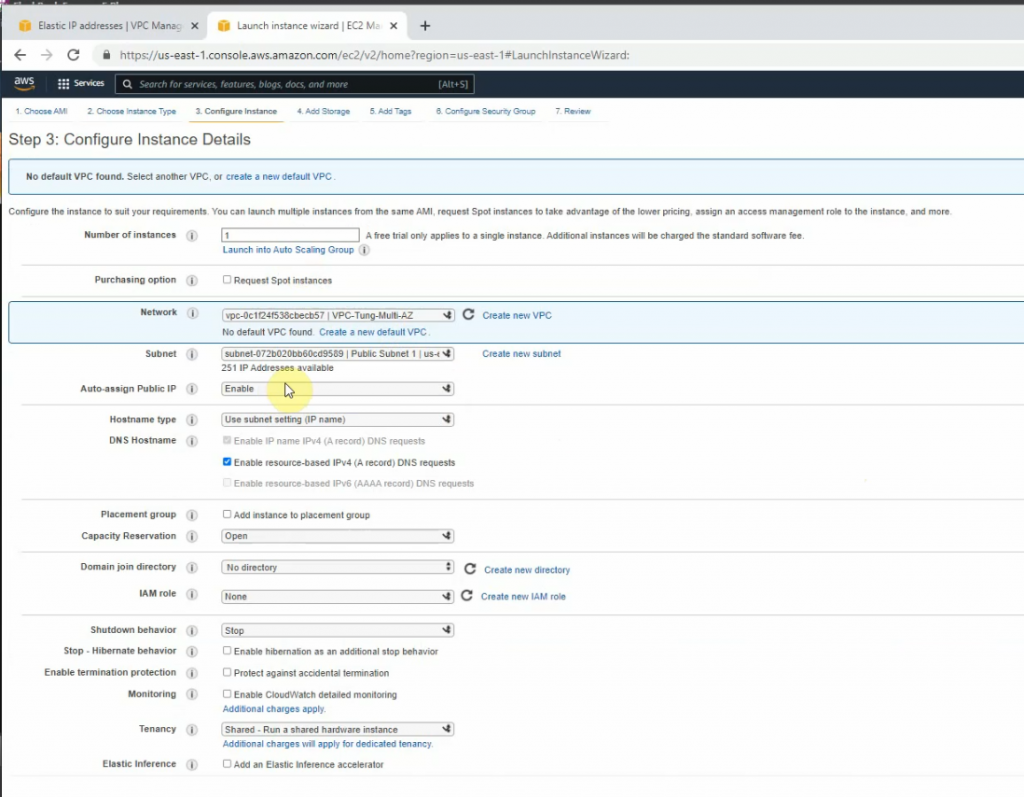
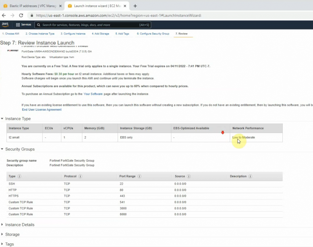
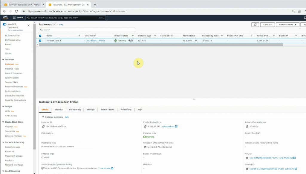
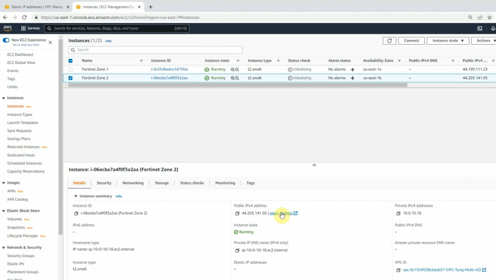
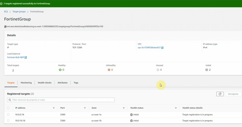
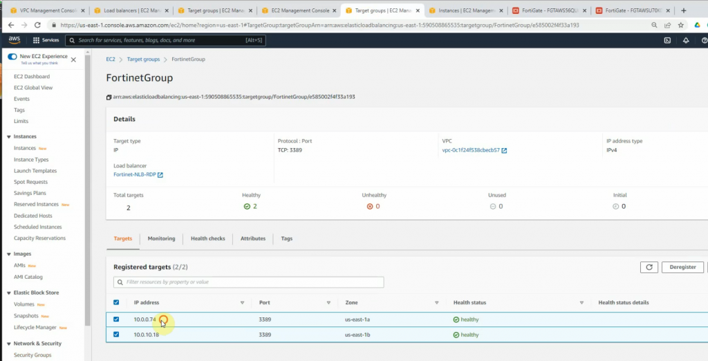
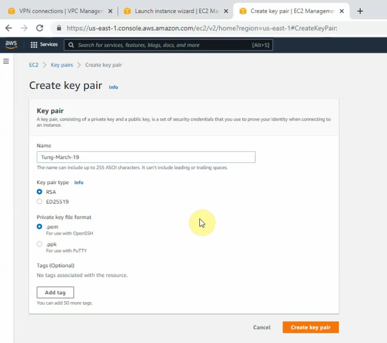
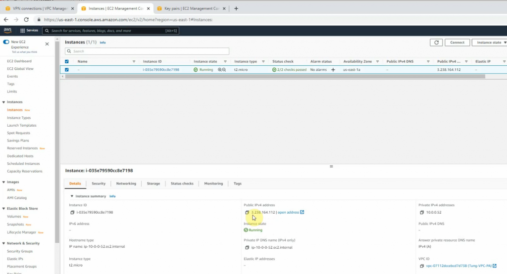
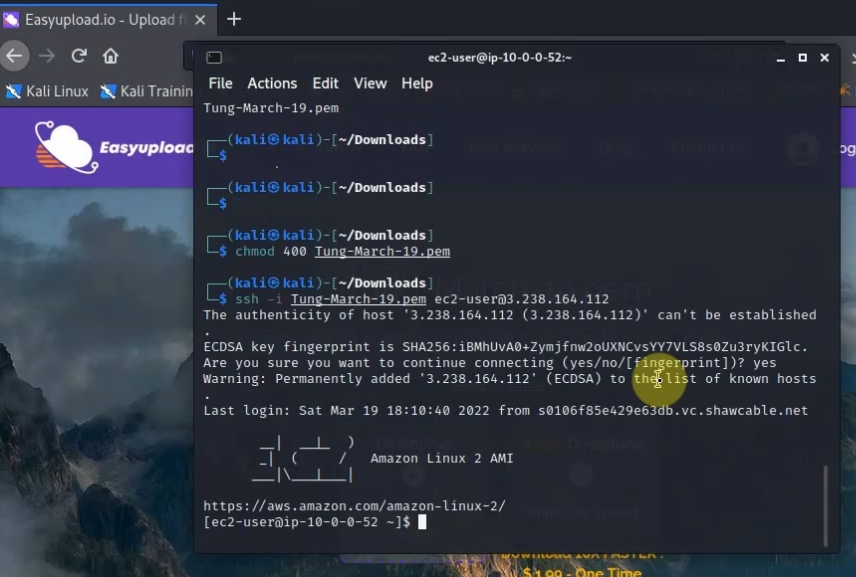
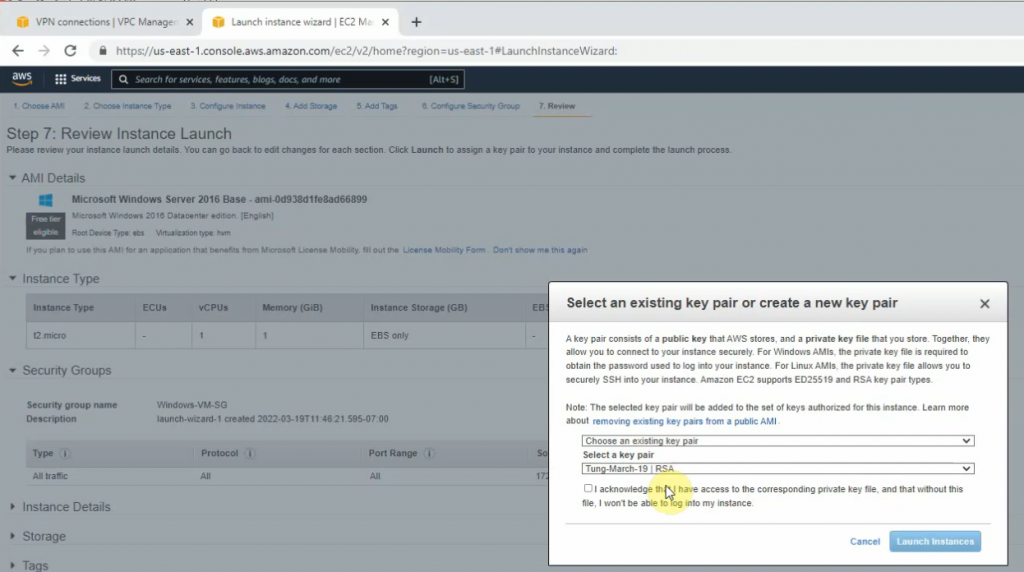
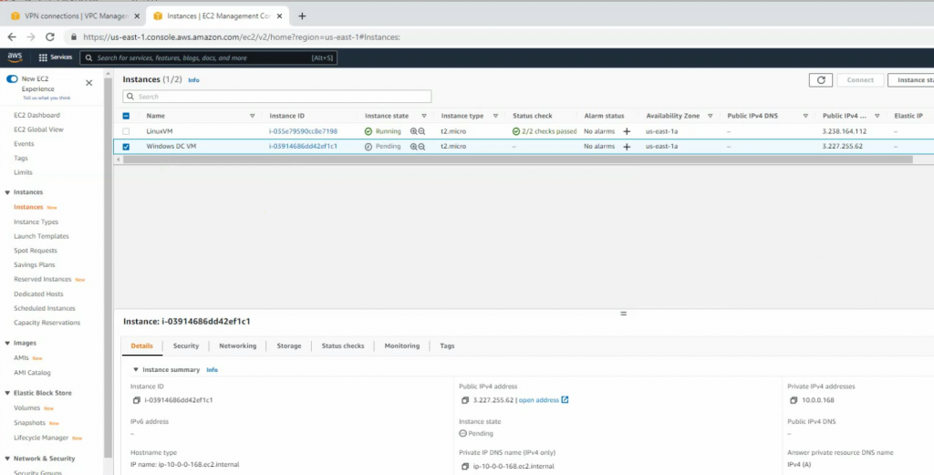
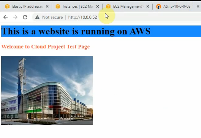
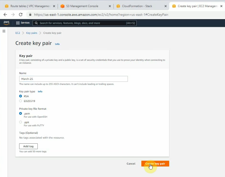
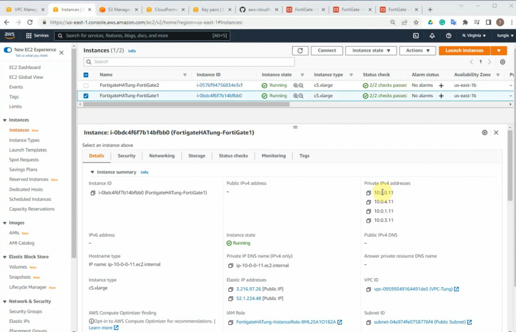
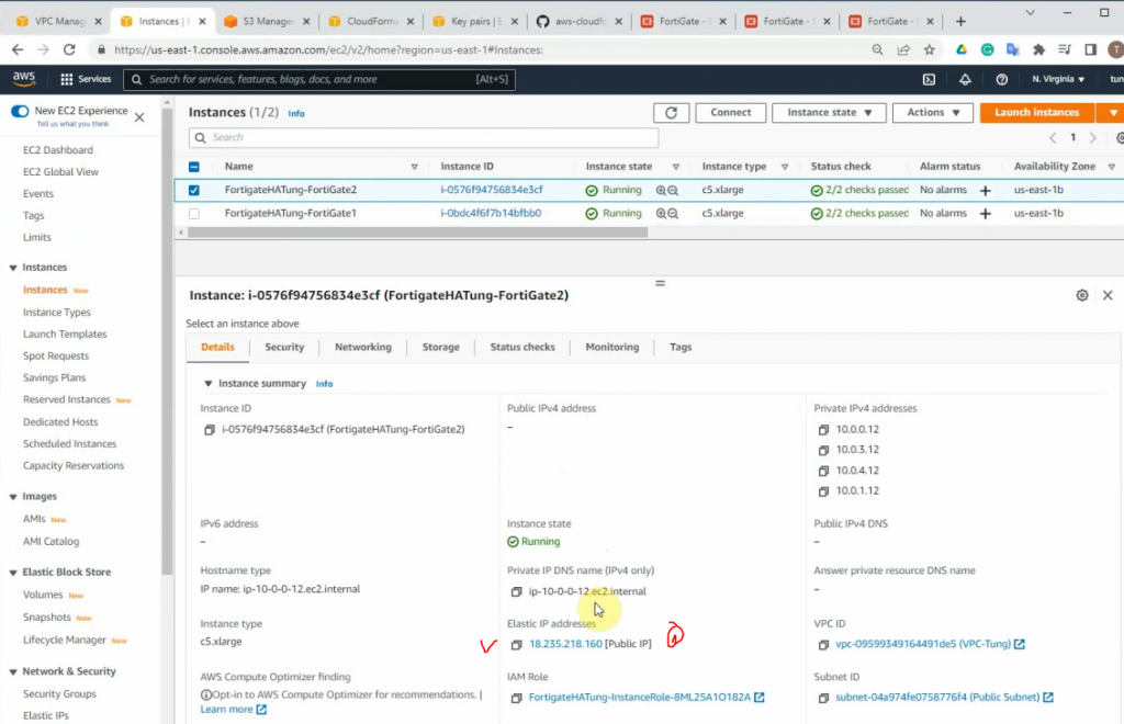
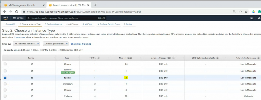
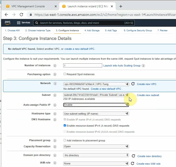
Back to AWS and launch a new Linux VM instance. This machine is used to test VPN site-to-site.
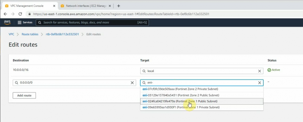
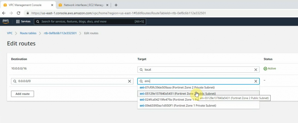
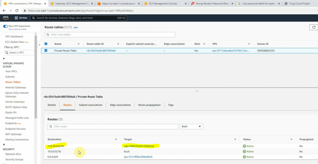
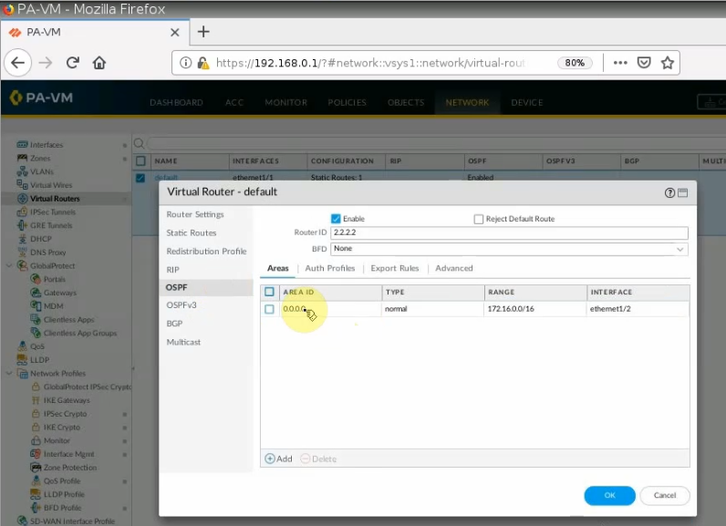
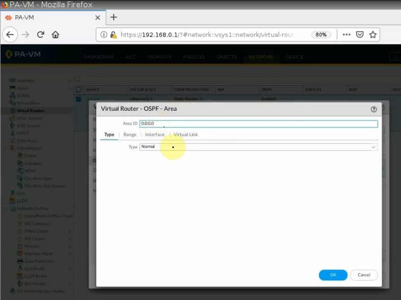
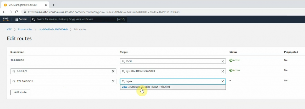
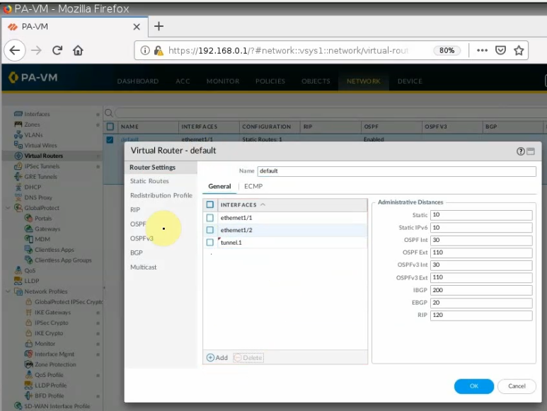
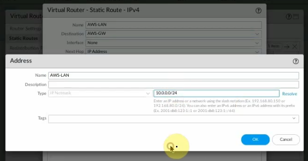
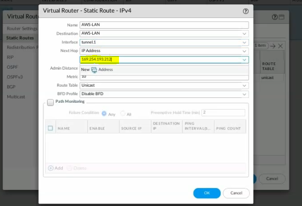
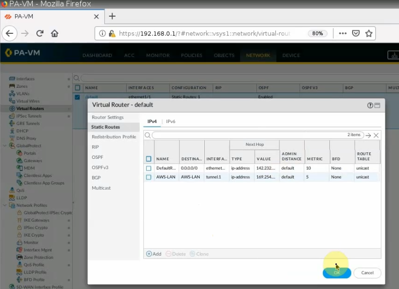
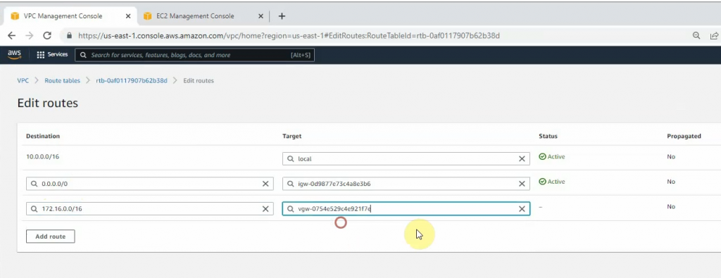
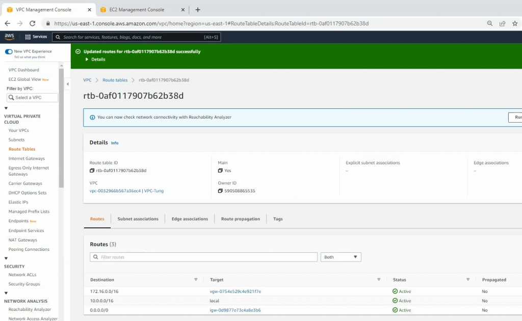
Configure a new static route to allow LAN subnets on AWS to access LAN subnets on FortiGate.
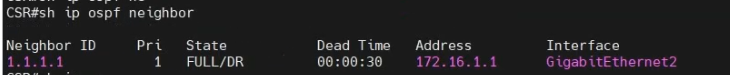
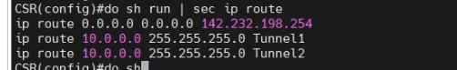
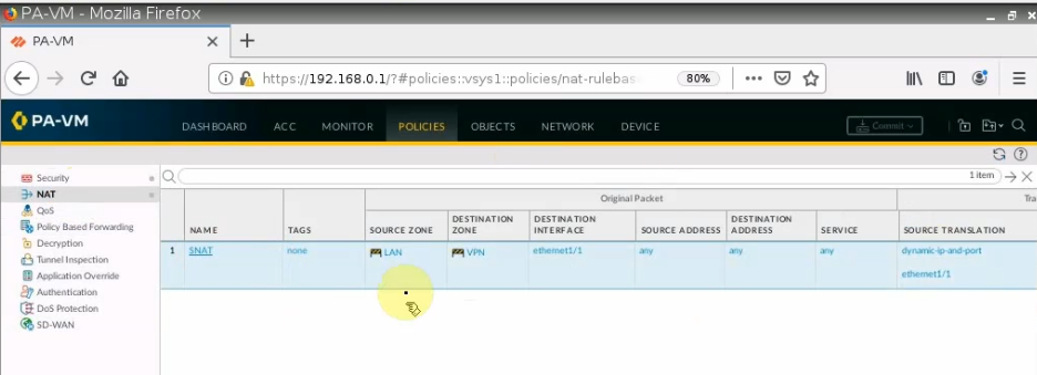
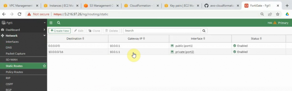
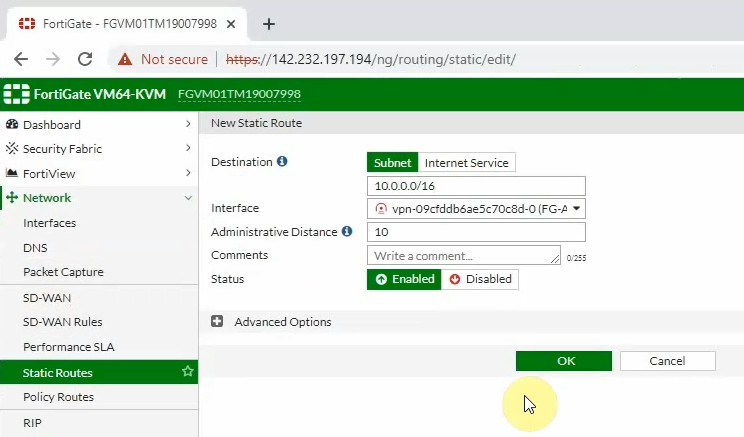
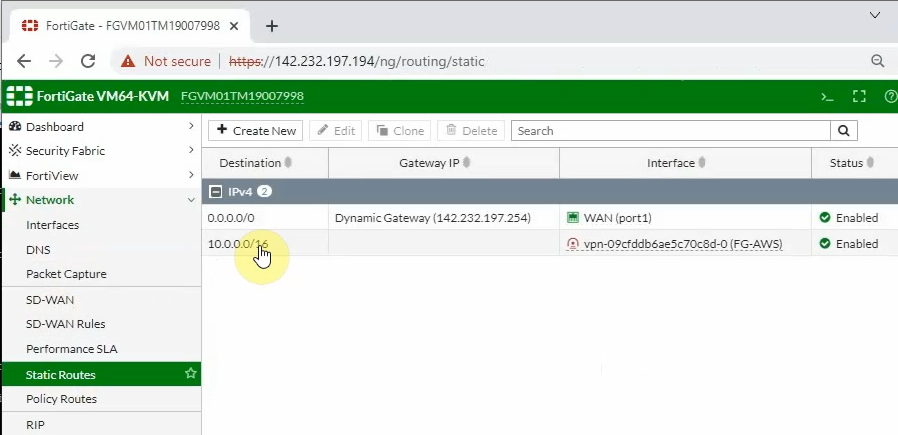
On FortiGate, configure a new static route to AWS LAN subnets.
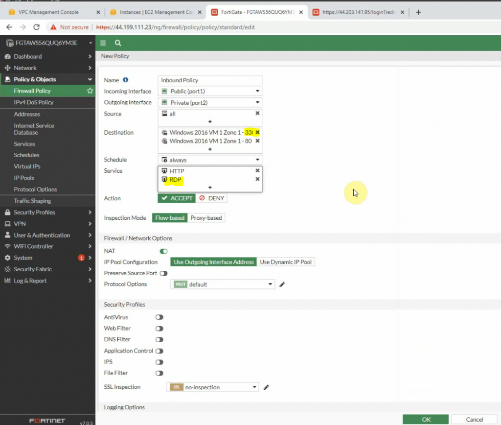
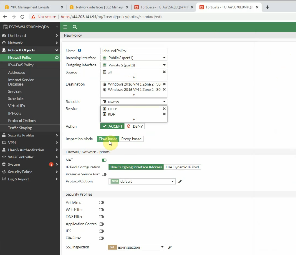
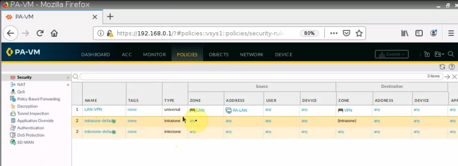
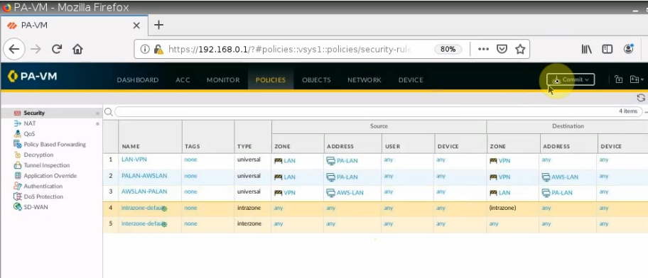
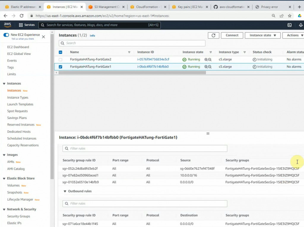
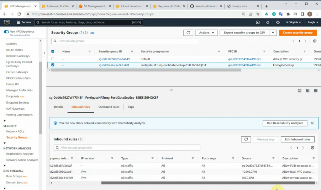
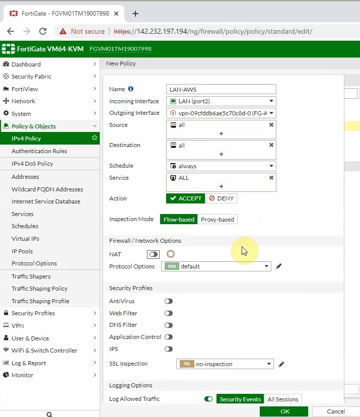
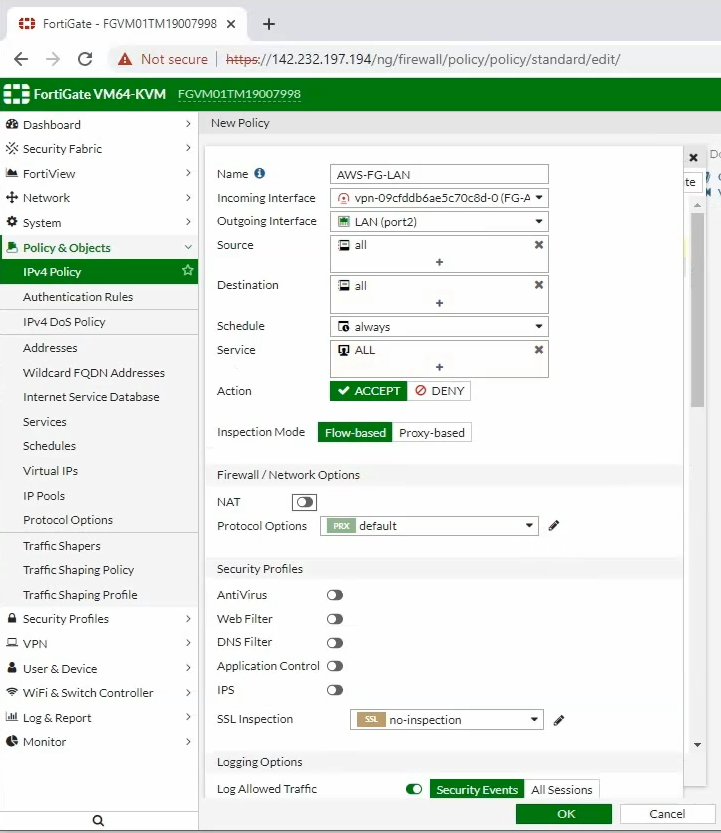
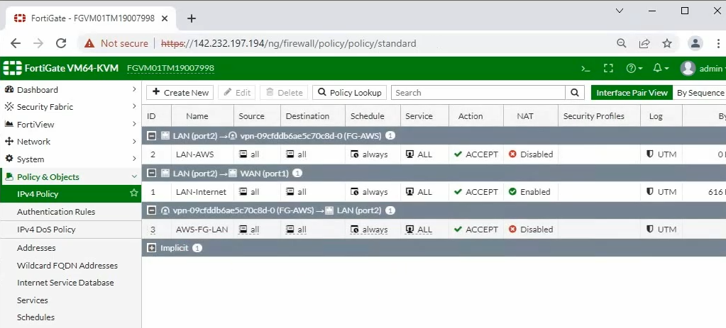
Configure access rules to allow FortiGate LAN subnets to communicate with AWS LAN subnets.
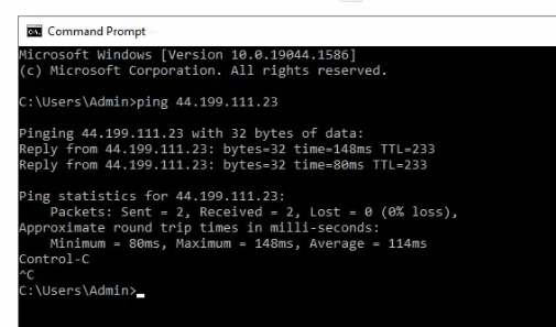
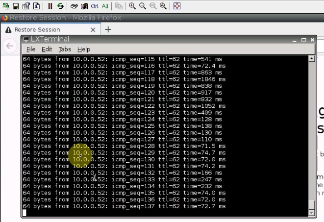
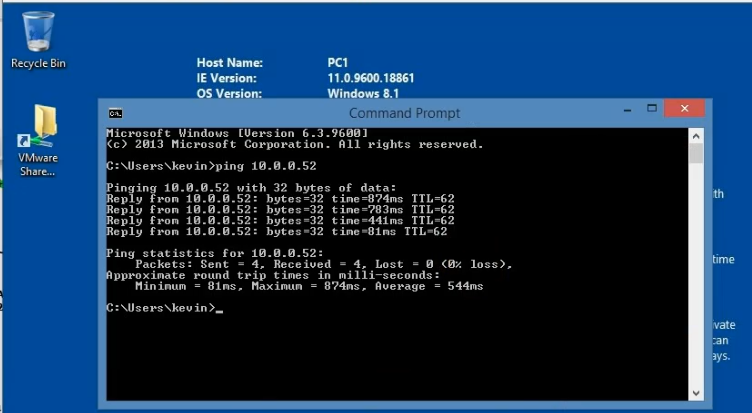
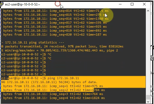
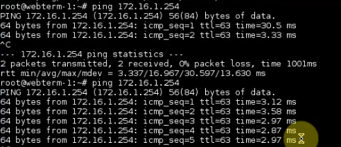
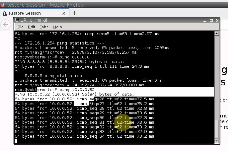
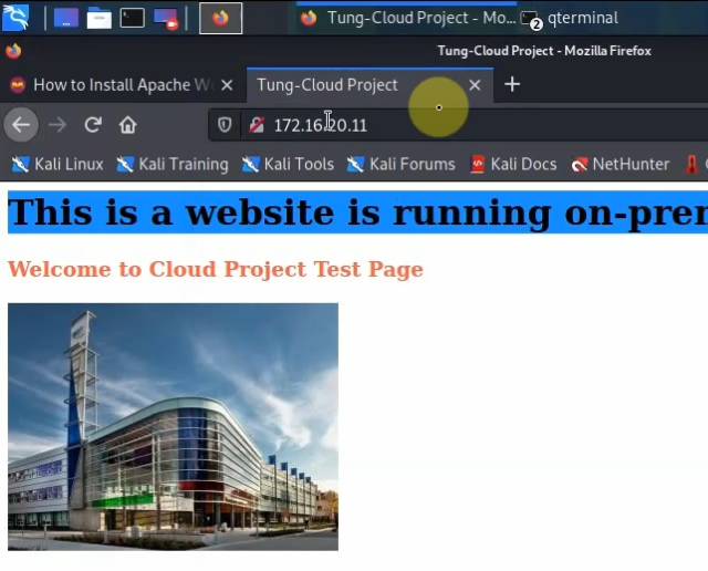
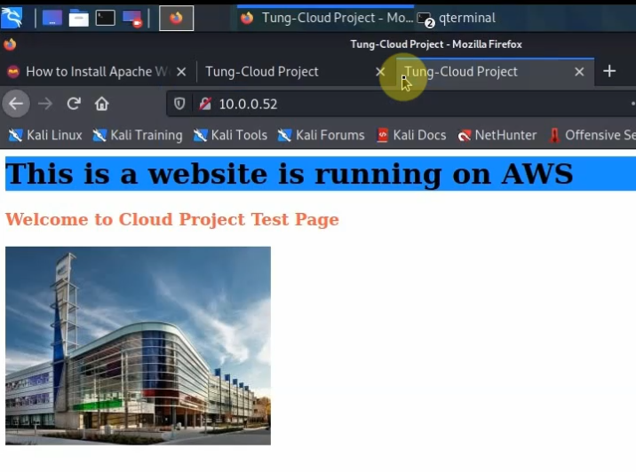
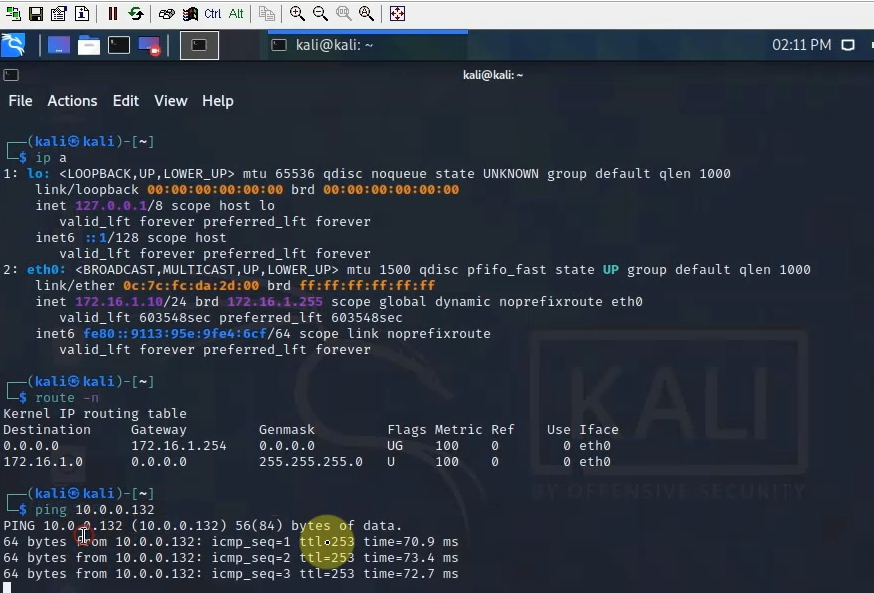
Pings from Kali machine to the Linux VM instance on AWS.
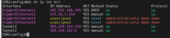
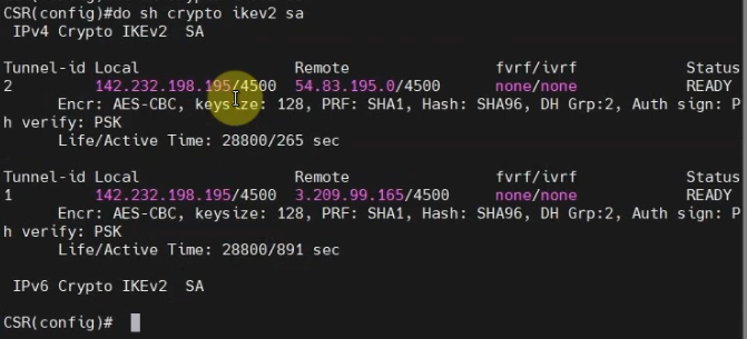
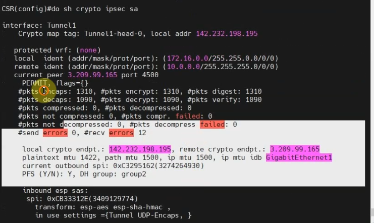
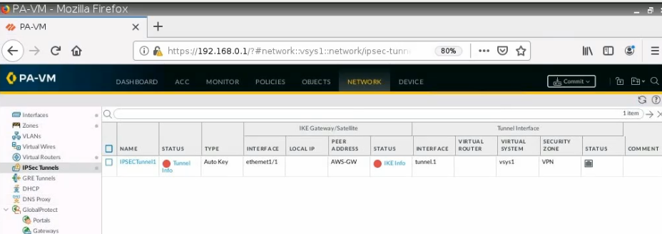
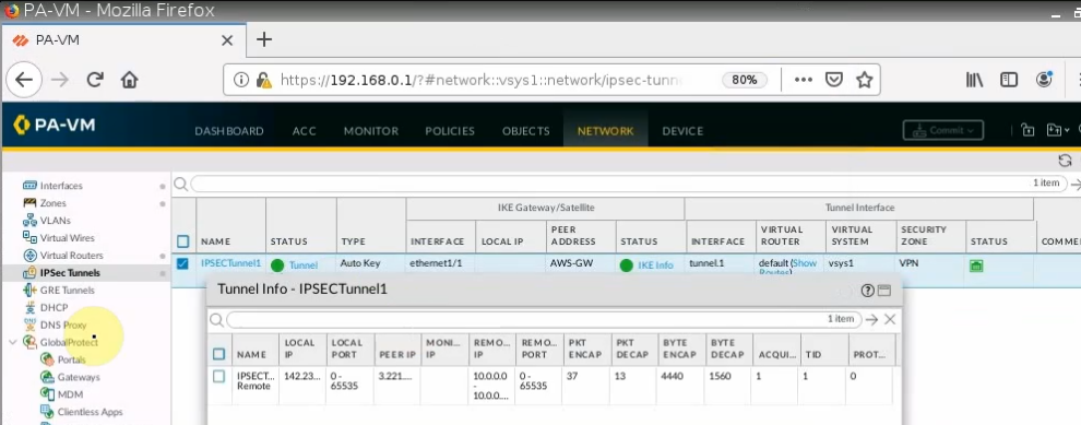
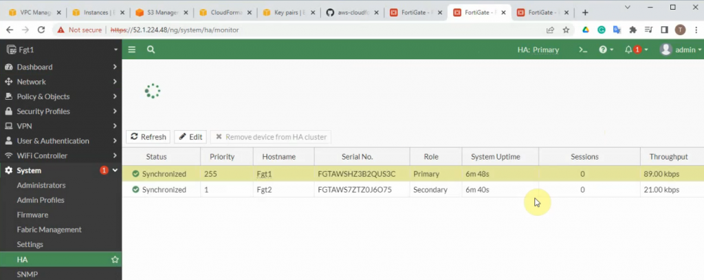
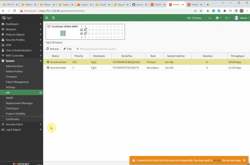
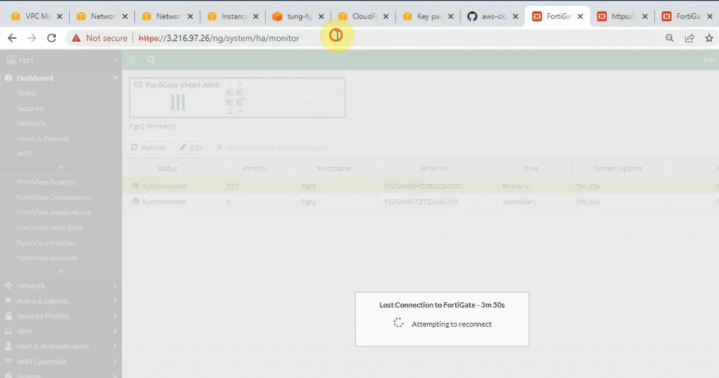
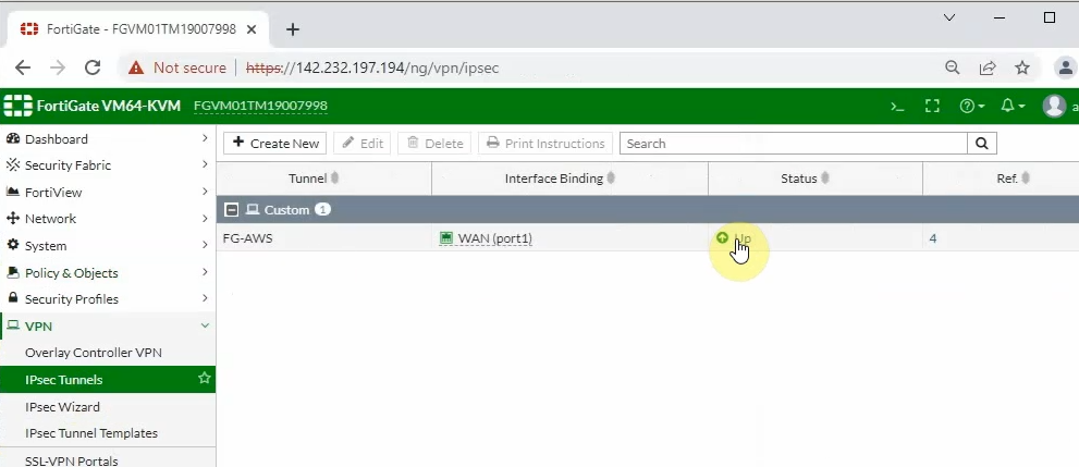
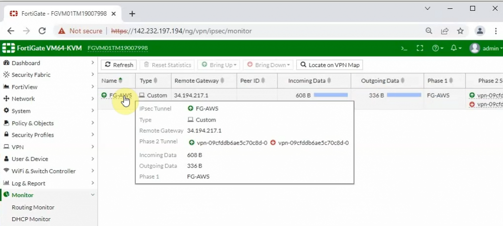
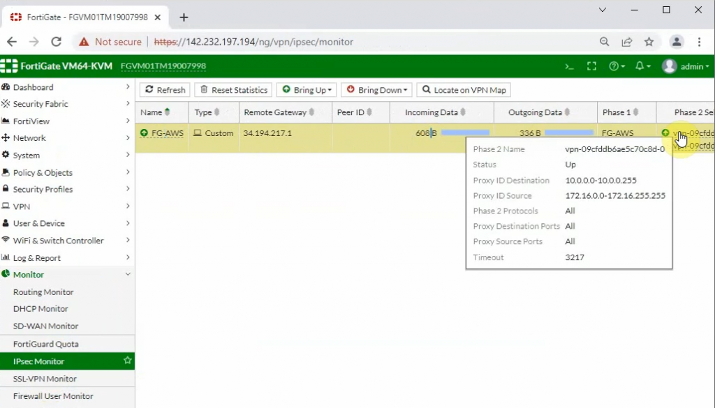
The IPSEC tunnel in FortiGate is up.
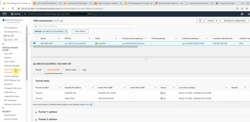
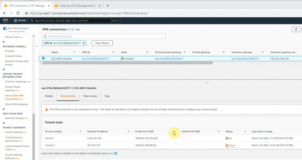
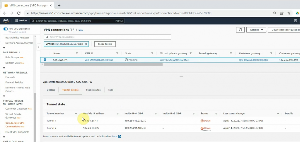
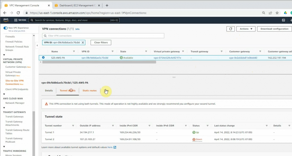
Back to AWS, the VPN tunnel is up.
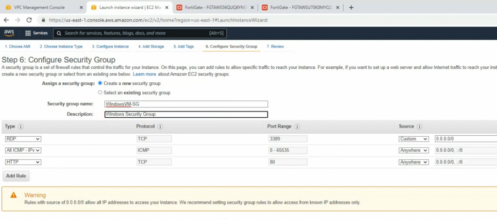
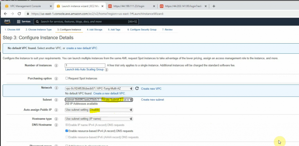
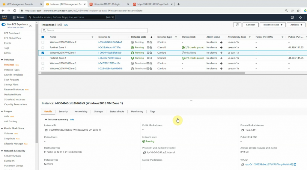
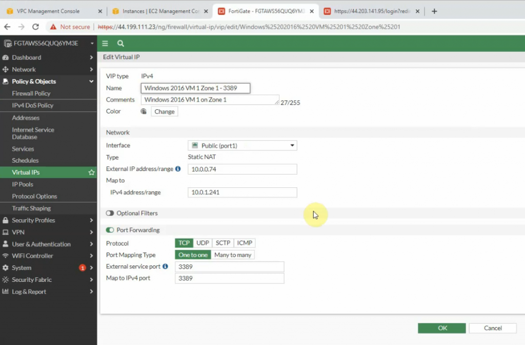
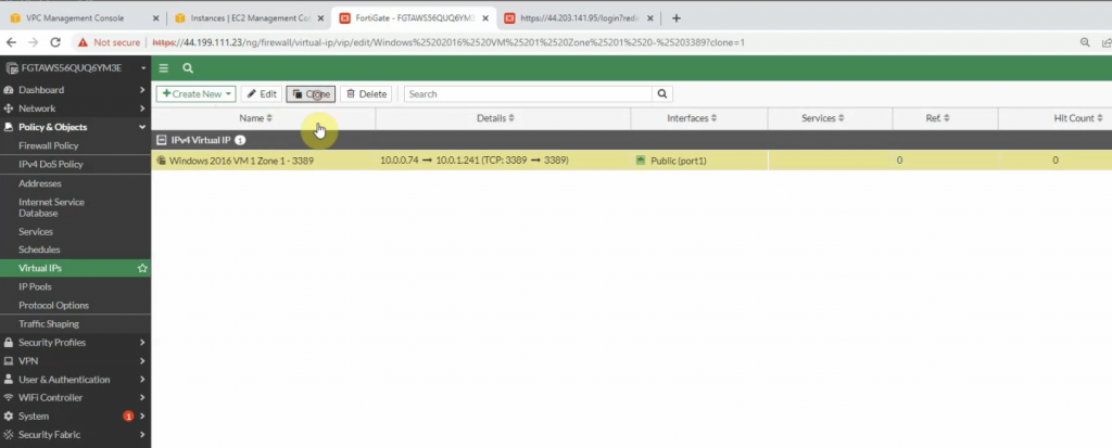
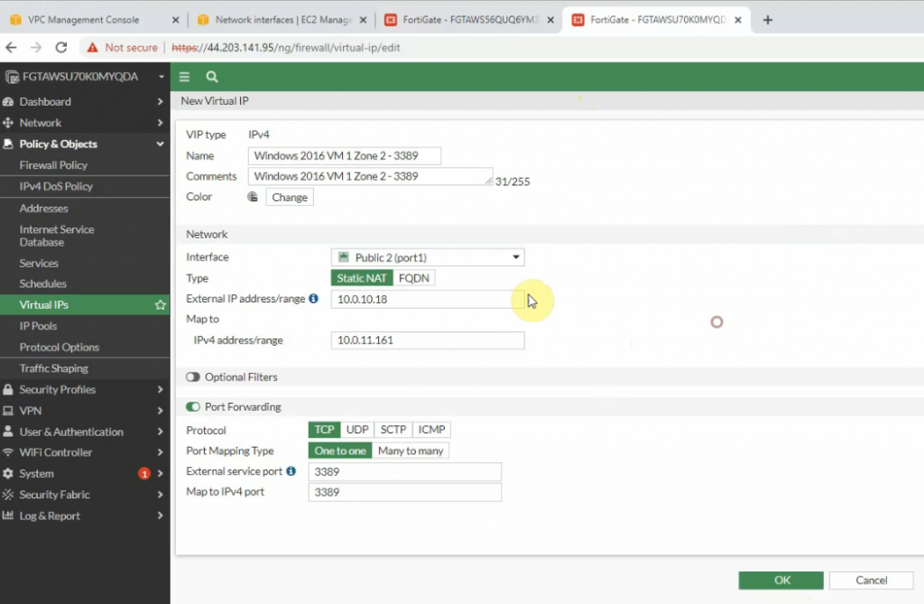
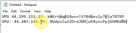
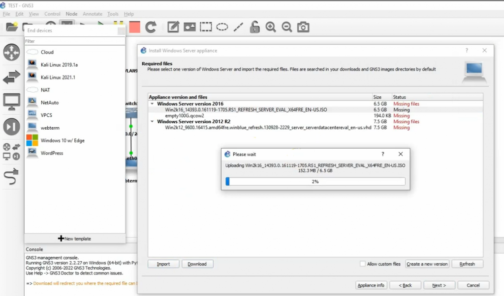
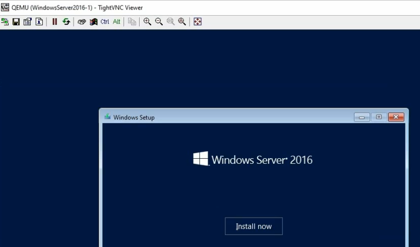
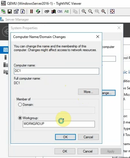
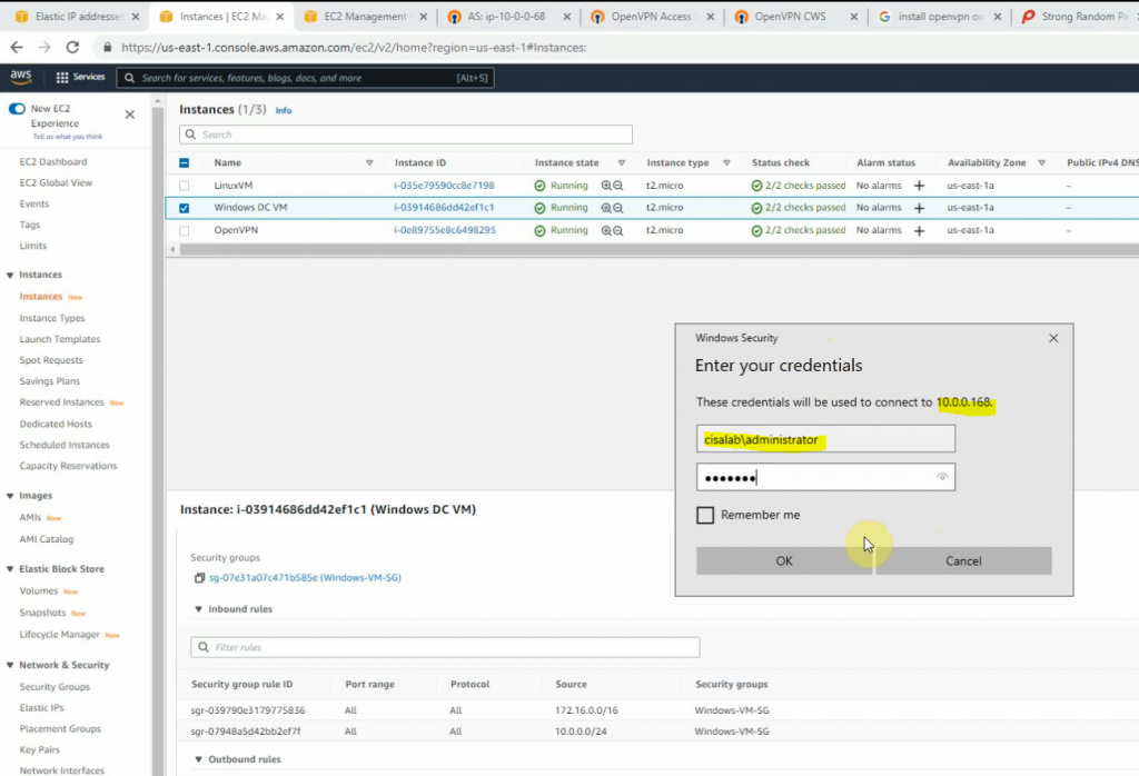
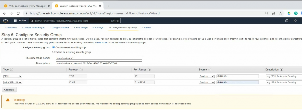
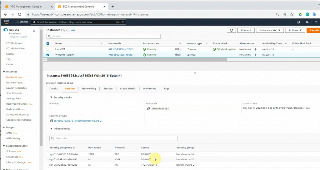
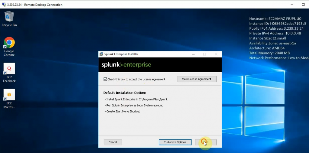
Launches a new Windows 2016 VM instance to install Splunk.
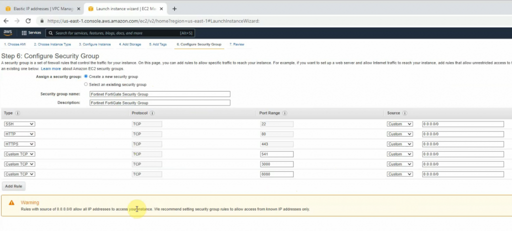
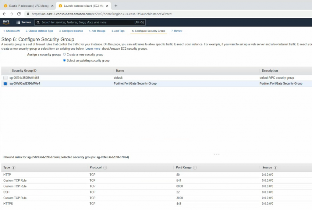
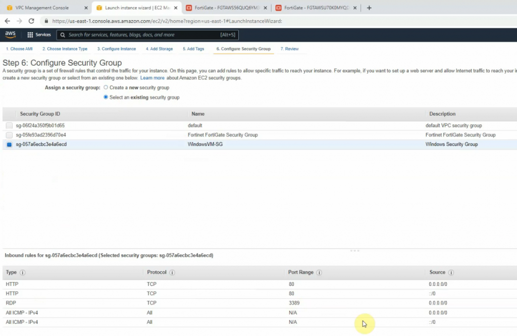
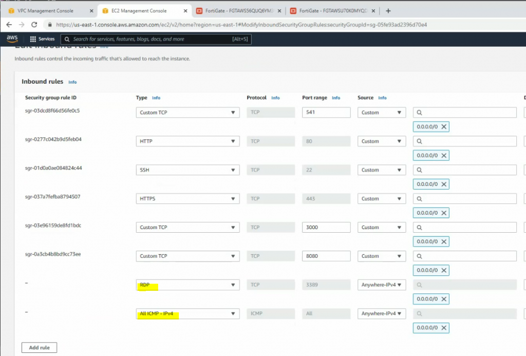
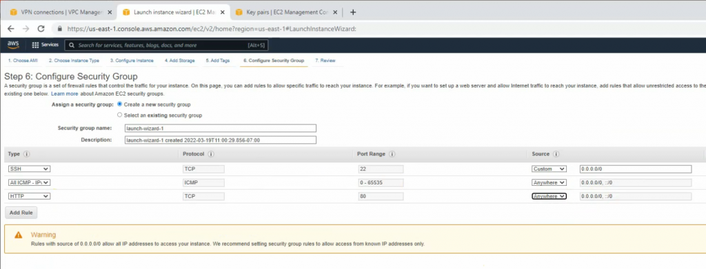
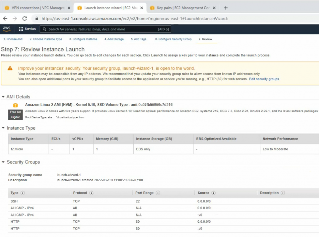
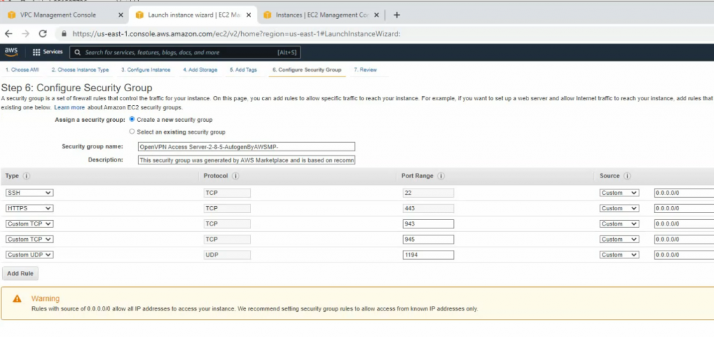
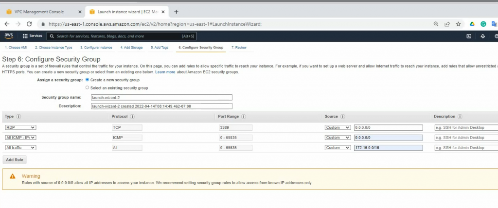
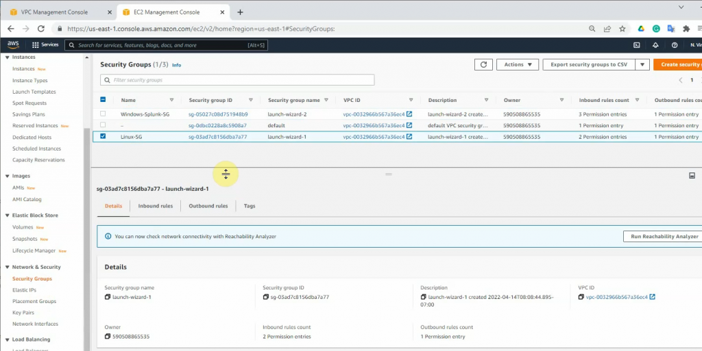
On Security Group, add a couple of rules to allow ICMP and all traffic on FortiGate LAN subnets to access this instance.
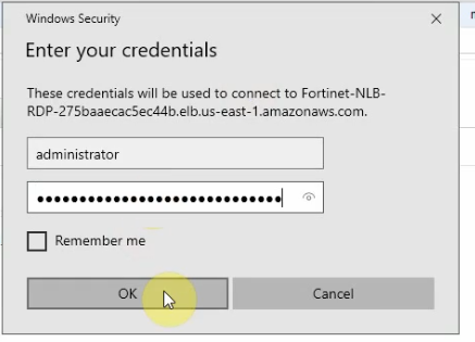
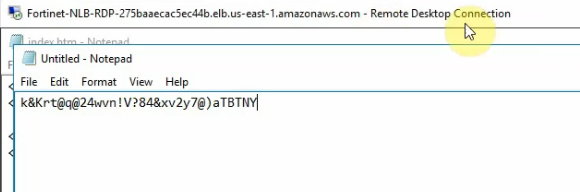
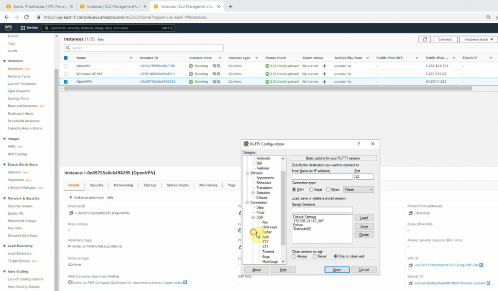
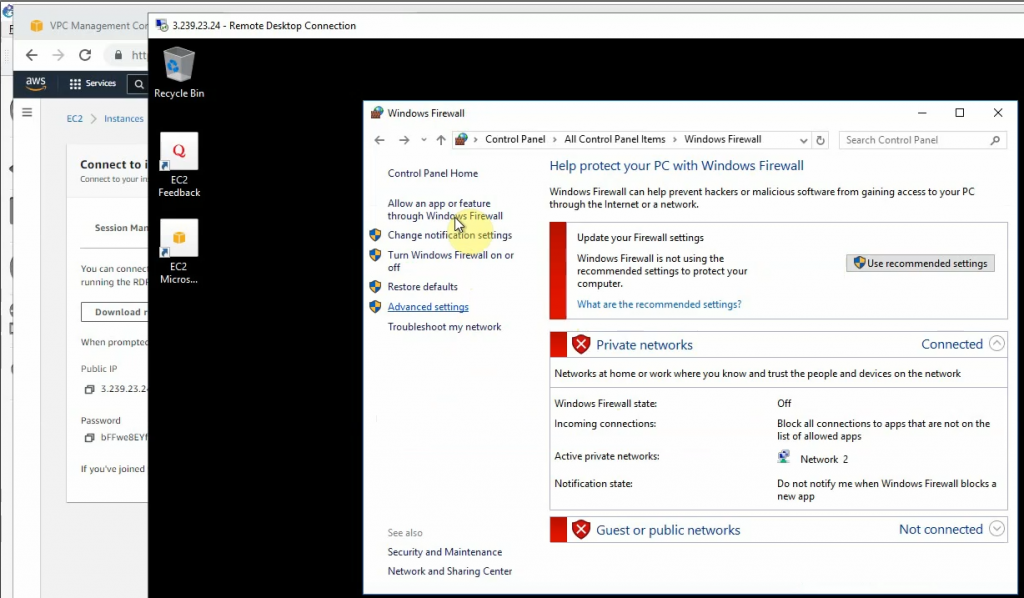
RDP to Windows instance and disable Firewall to send logs from FortiGate.
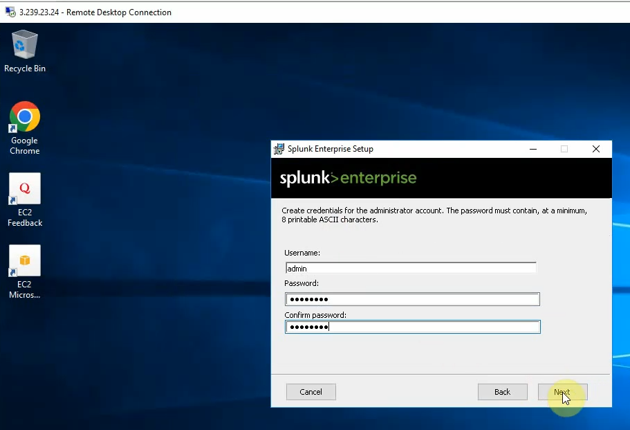
Download Splunk Enterprise for Windows and install it into this instance.
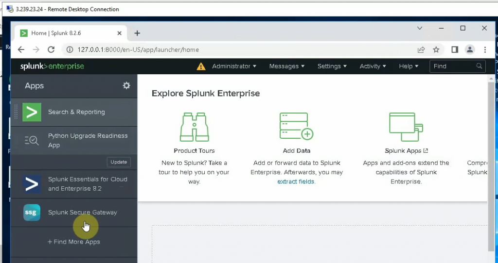
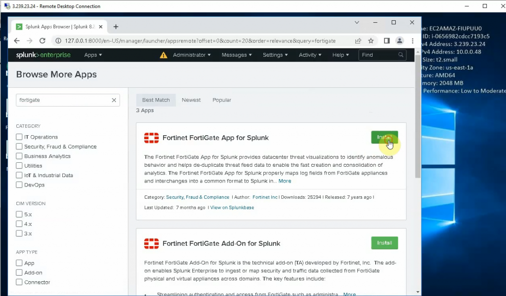
Install FortiGate App for Splunk and Fortinet FortiGate Add on Splunk.
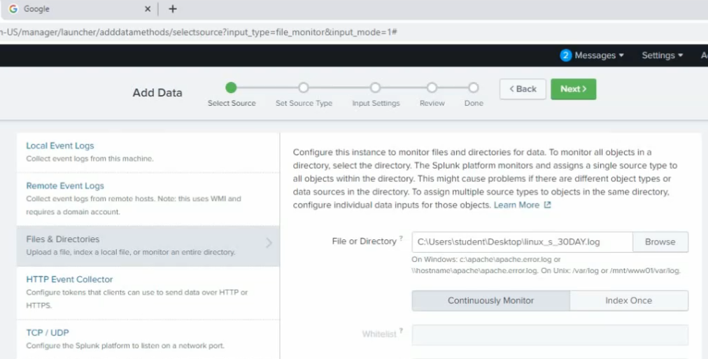
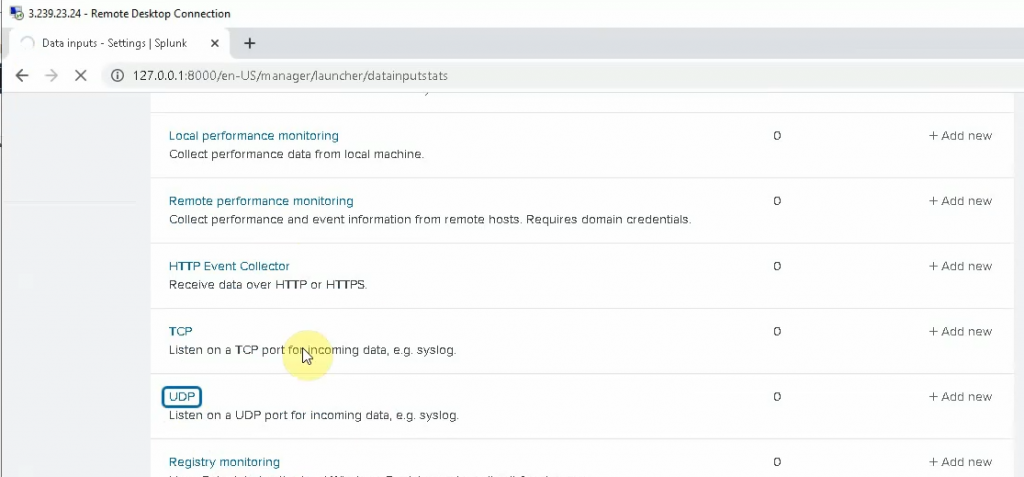
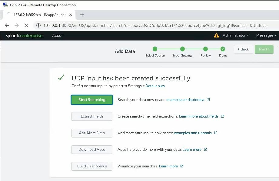
Click on the Settings tab and configure Splunk to get FortiGate logs. Select new Local UDP.
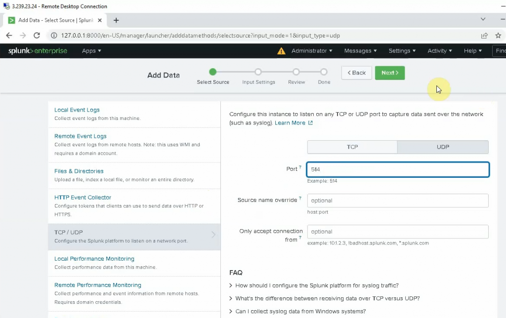
Enter 514 on the port setting. Be default, FortiGate is using UDP port 514 to send log to Syslog.
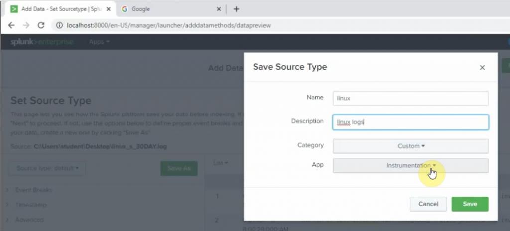
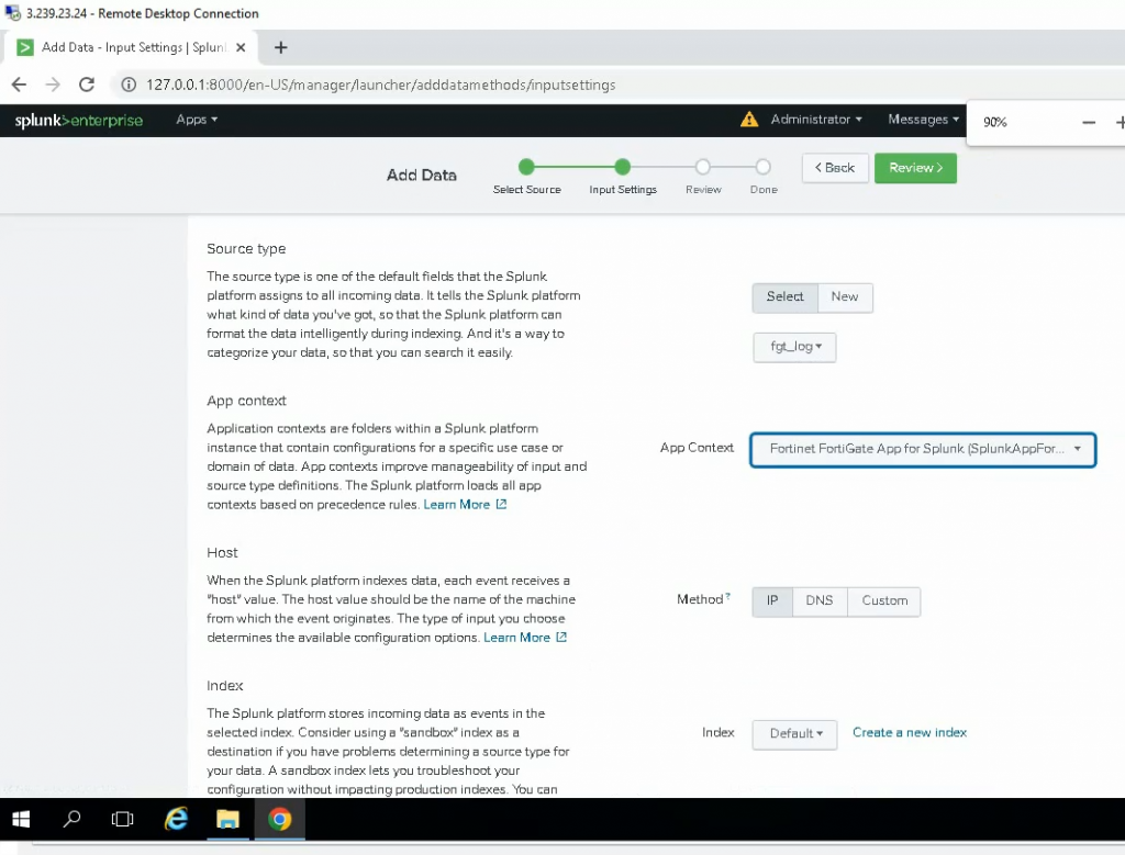
Select: fgt_log
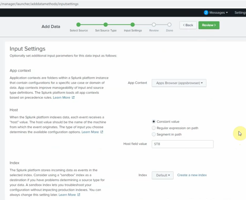
App Context: Fortinet FortiGate App for Splunk
Method: IP
Index: Default
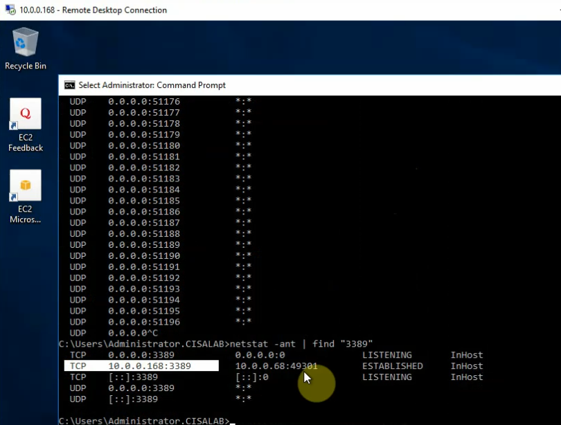
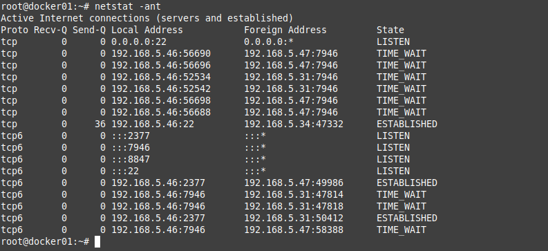
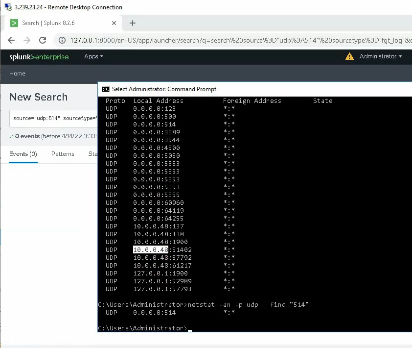
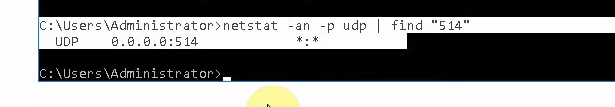
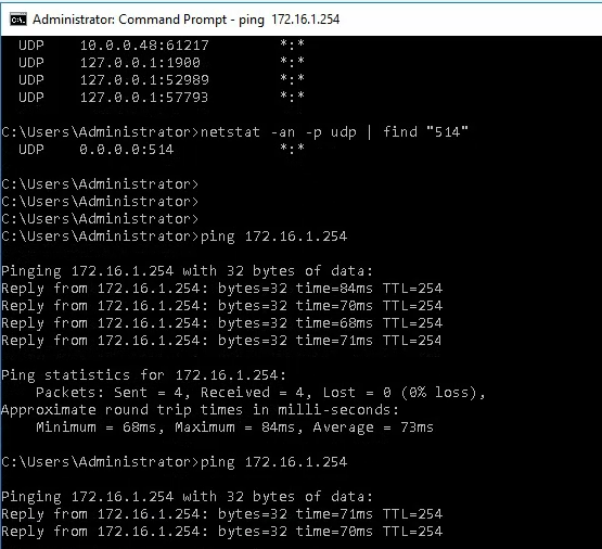
Check the UDP 514 port is running in the instance.
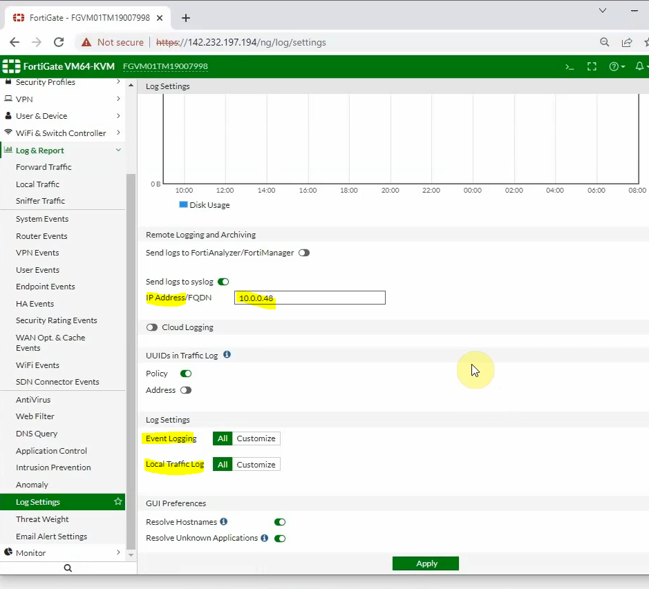
Back to FortiGate, configure Fortigate to send logs to Splunk on AWS. Enter the IP address of Splunk on the IP Address setting, and click choose All for “Event Logging” and “Local Logging”. Then, click Apply.
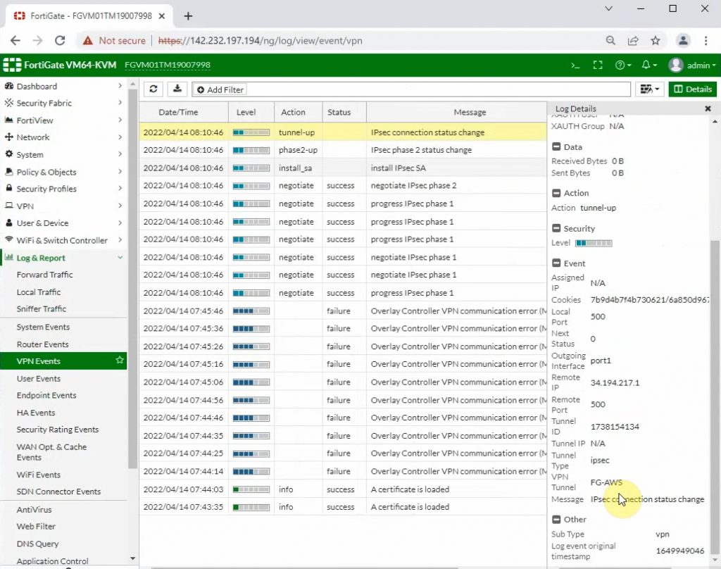
Log out of FortiGate and log back in to generate logs. If we may not see FortiGate logs on Splunk, we need to type the commands below to change the source-ip address to send log from using the “management interface” to using the LAN interface “172.16.1.254”
config log syslogd setting
    set status enable
    set mode udp
    set port 514
    set server "10.0.0.48"
    set source-ip "172.16.1.254"
end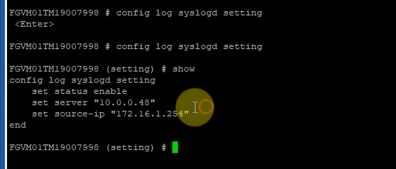
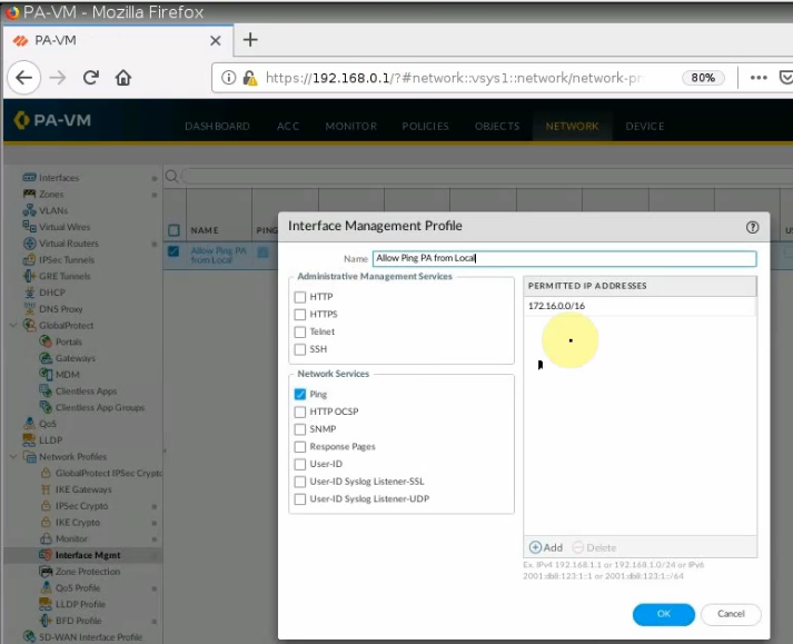
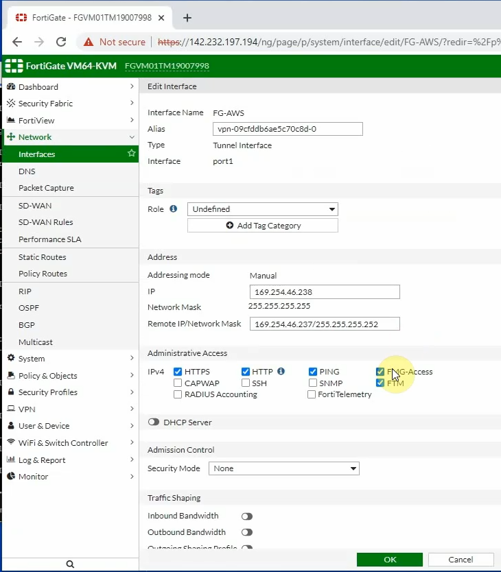
Also, enable PING Access, HTTP, and HTTPS on tunnel 1 interface of FortiGate.
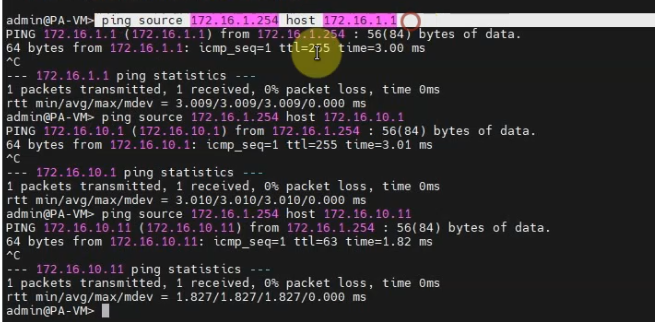
Splunk is able to ping the FortiGate LAN interface.
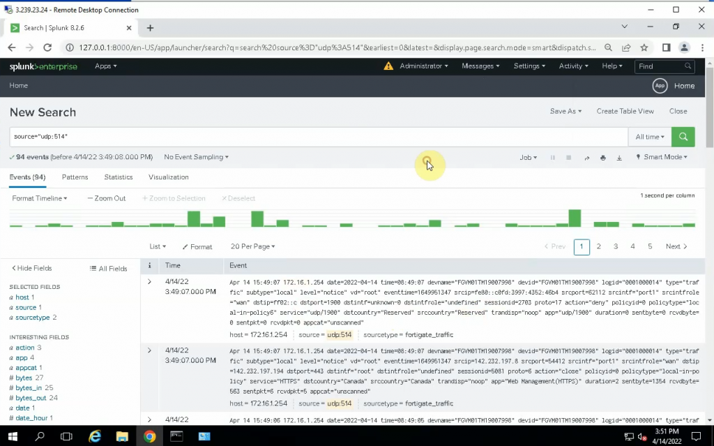
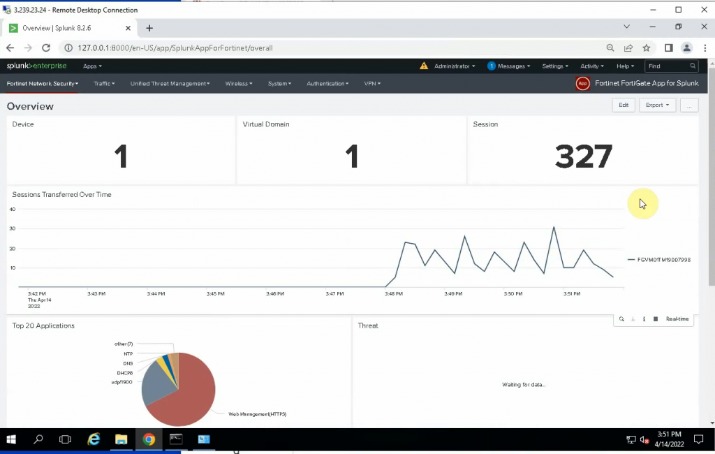
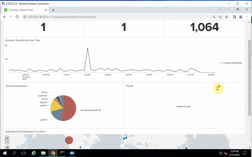
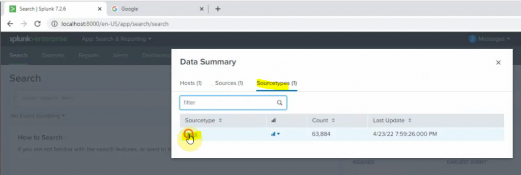
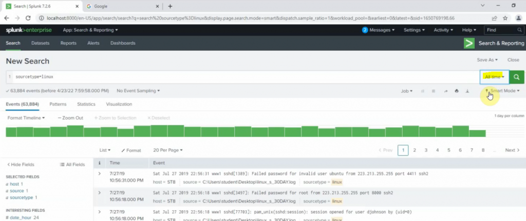
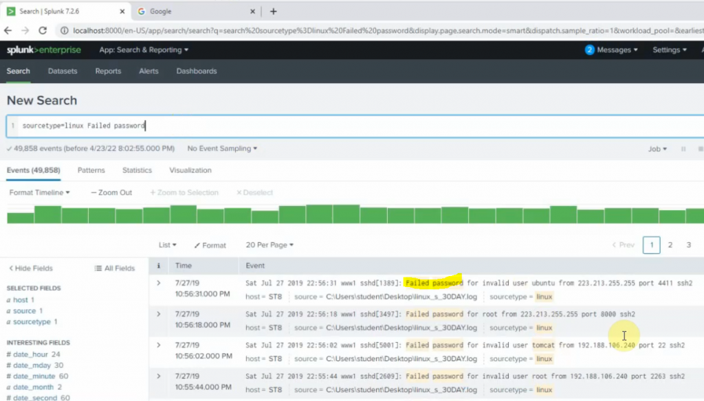
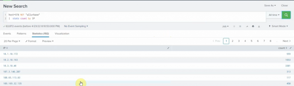
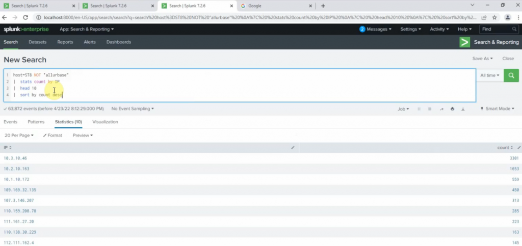
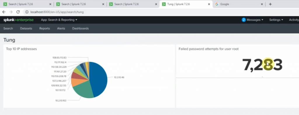
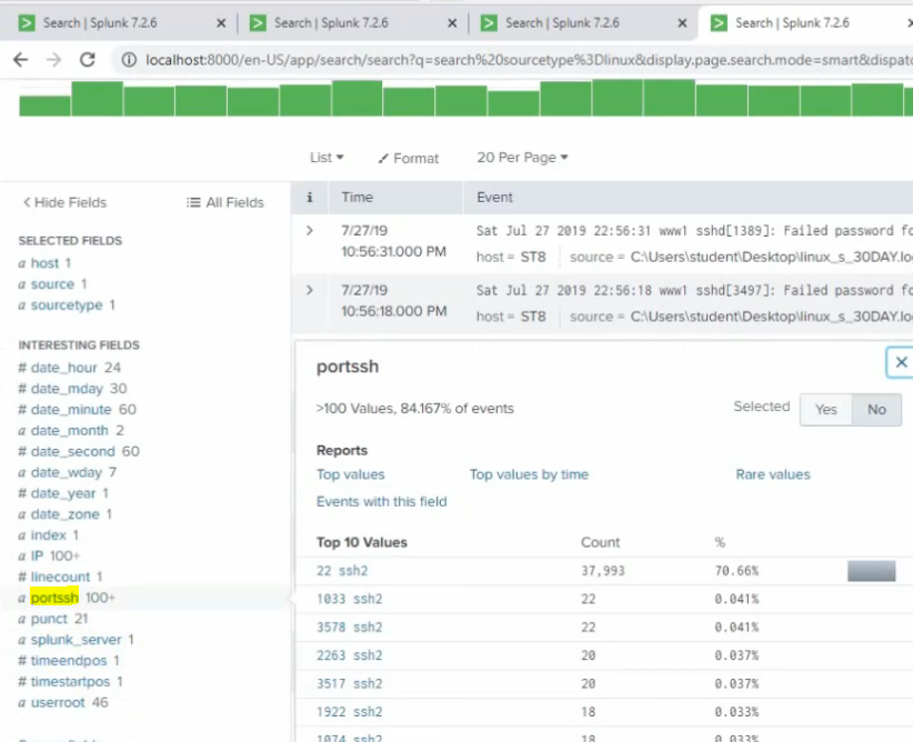
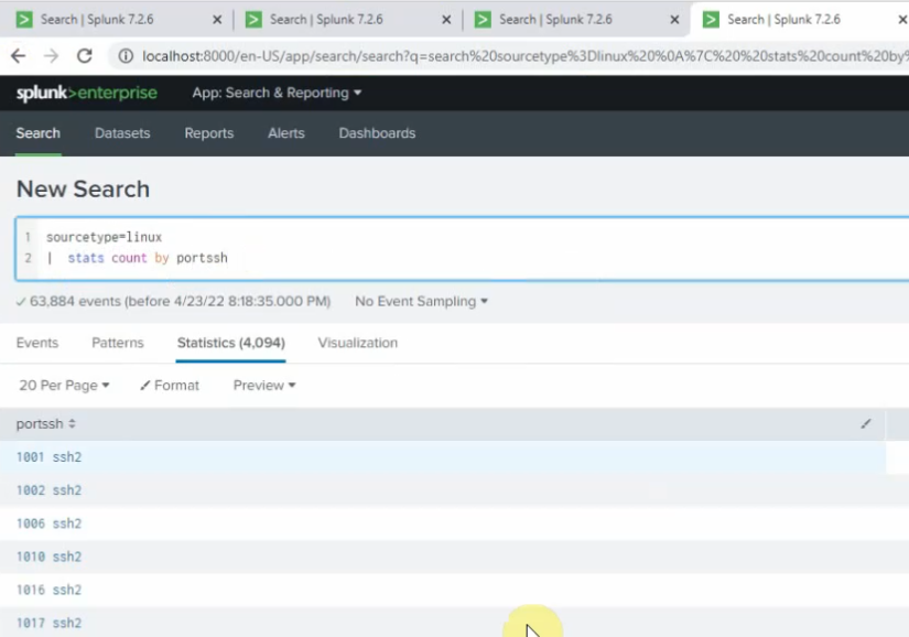
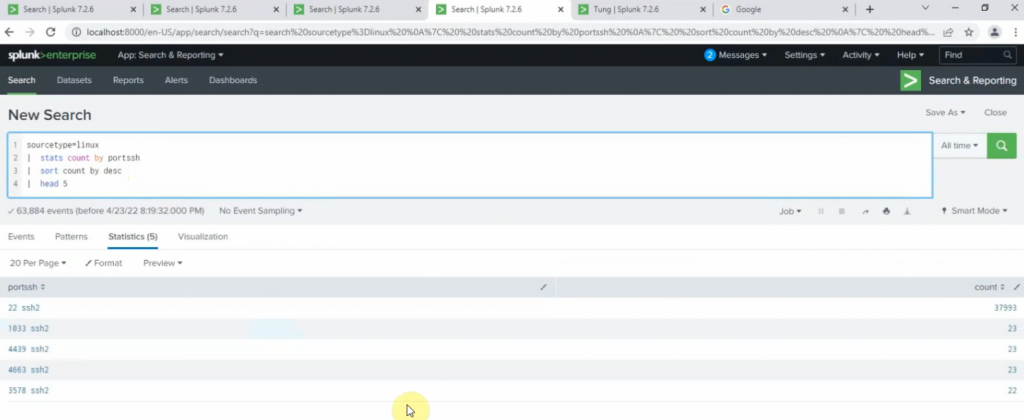
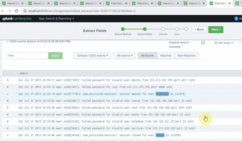
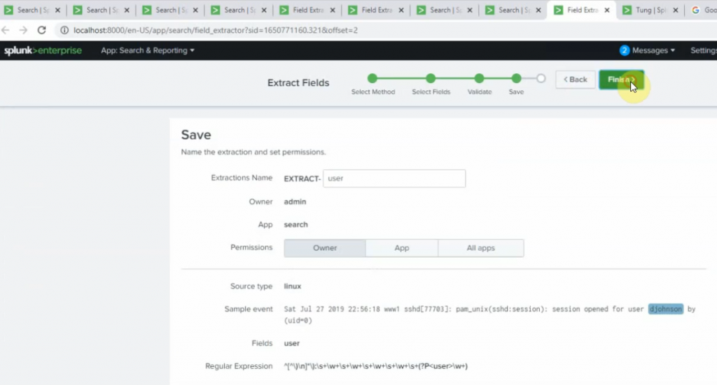
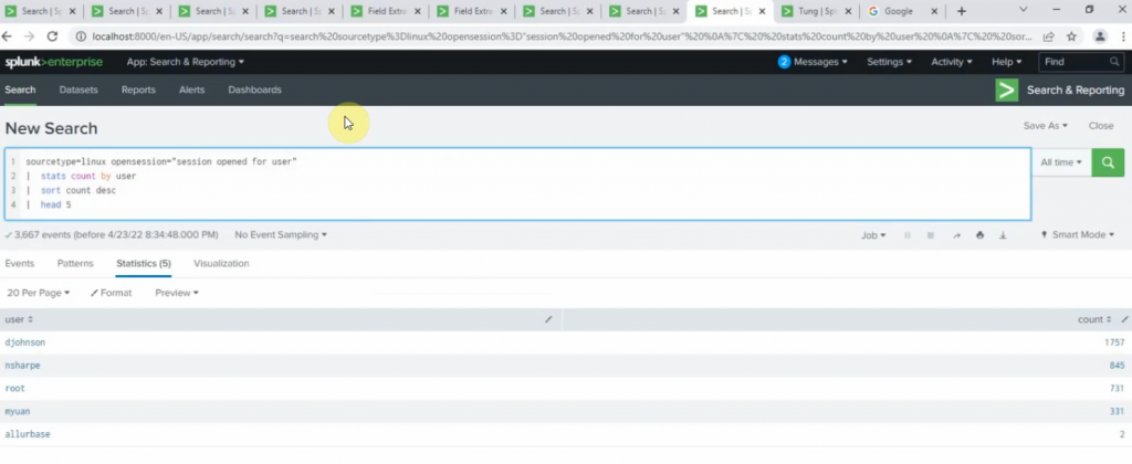
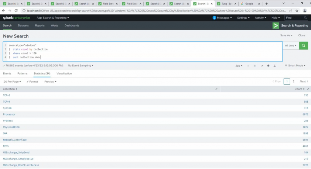
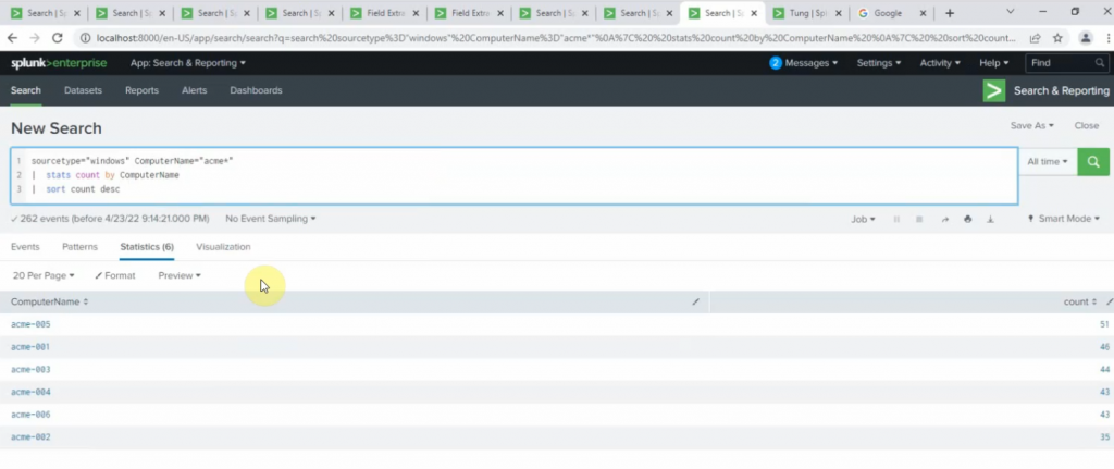
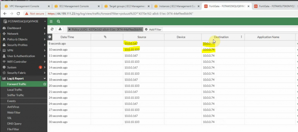
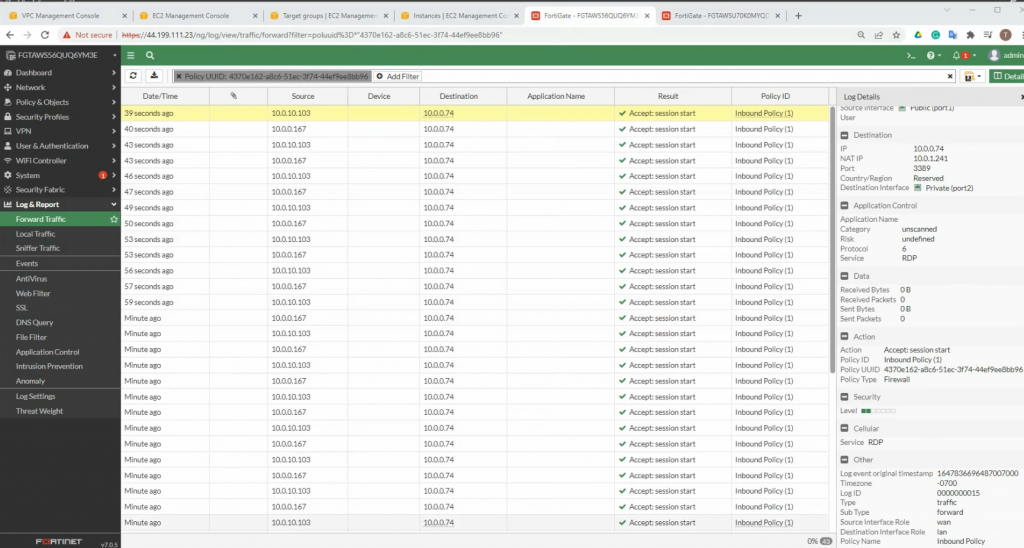
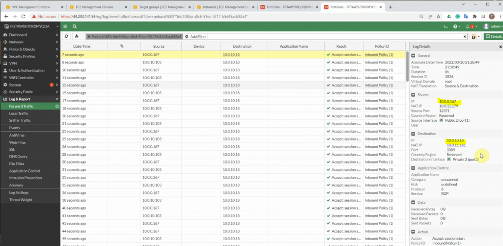
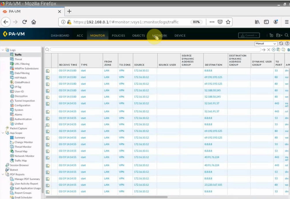
Back to the Splunk instance, now we are able to see logs from FortiGate.