Deploying Palo Alto Firewall in Amazon AWS

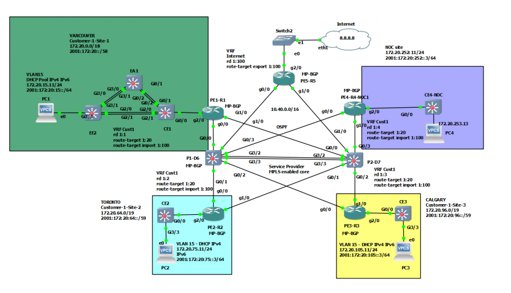
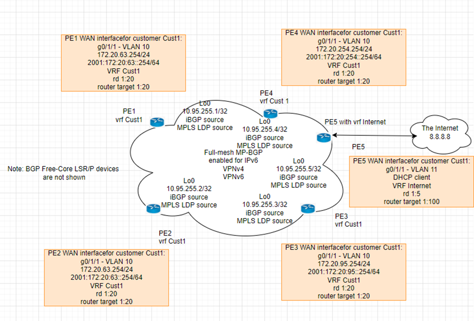
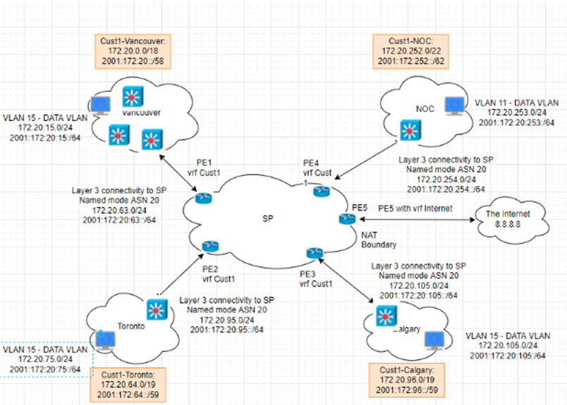
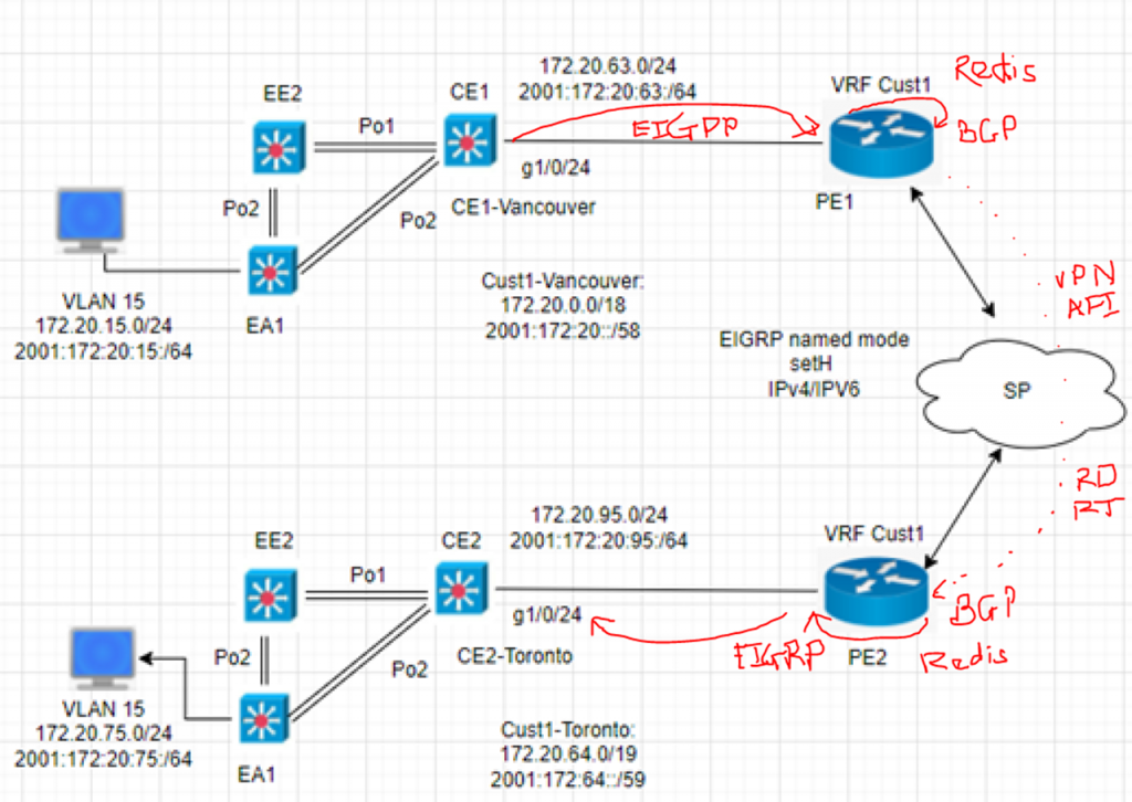
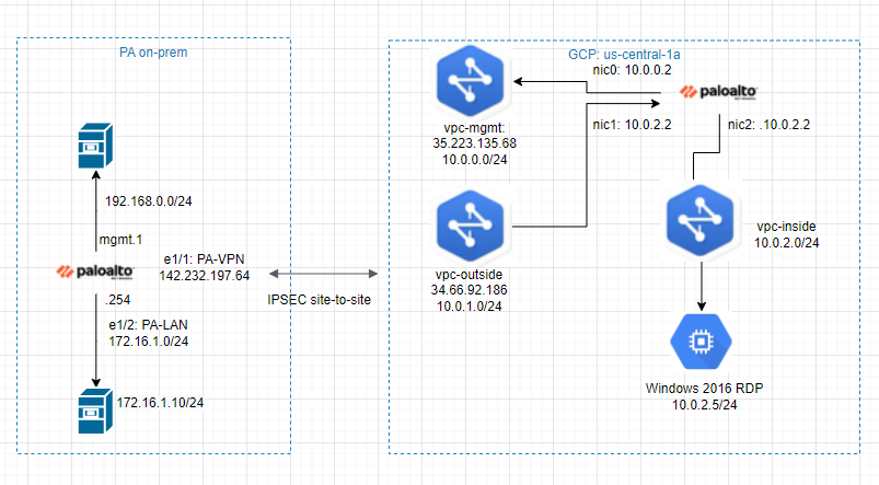
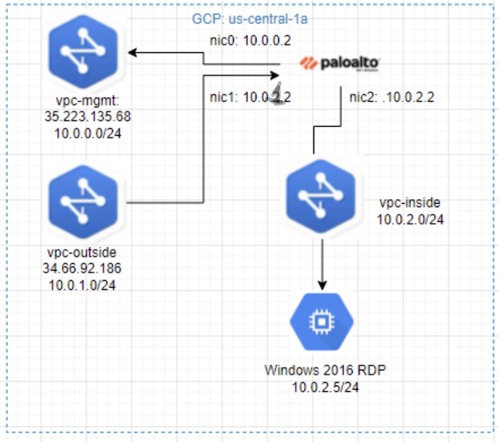
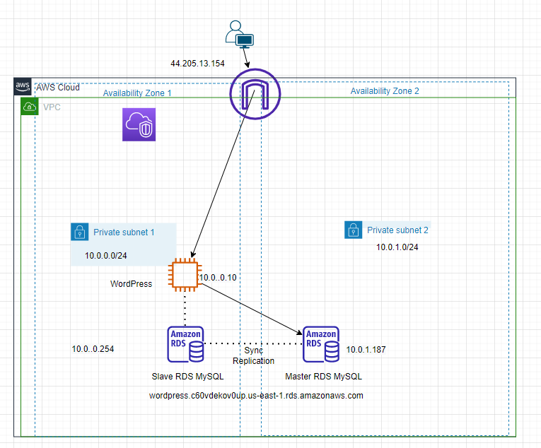
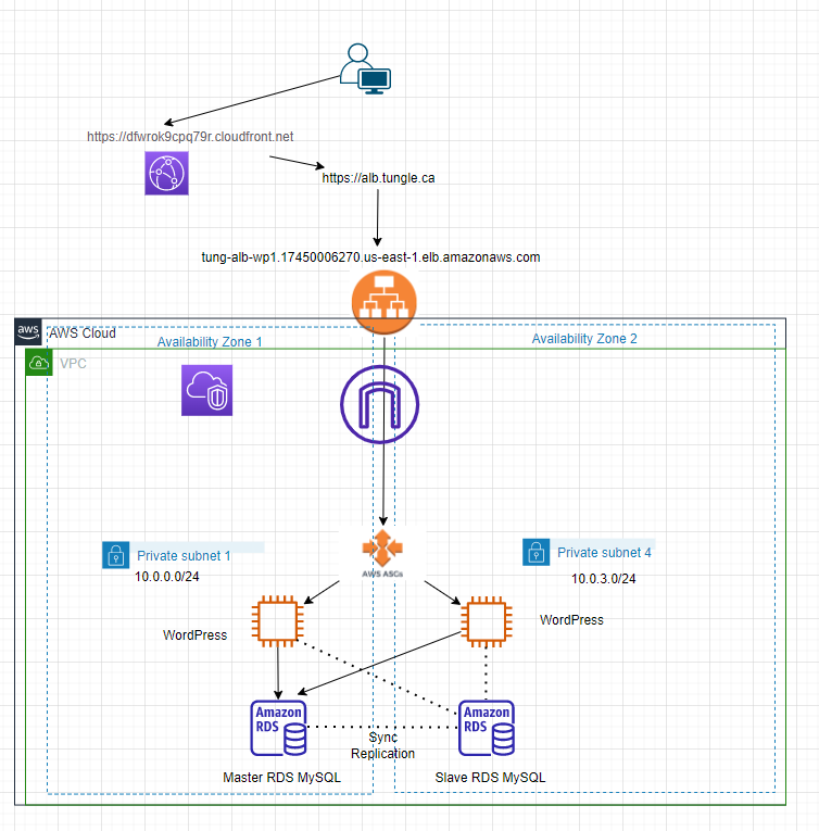
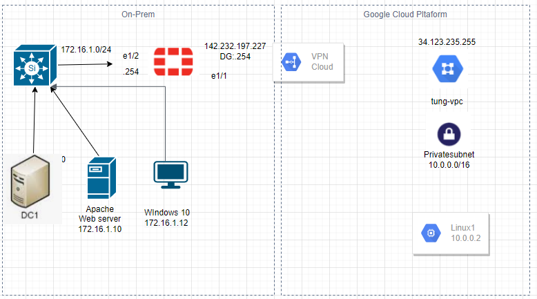
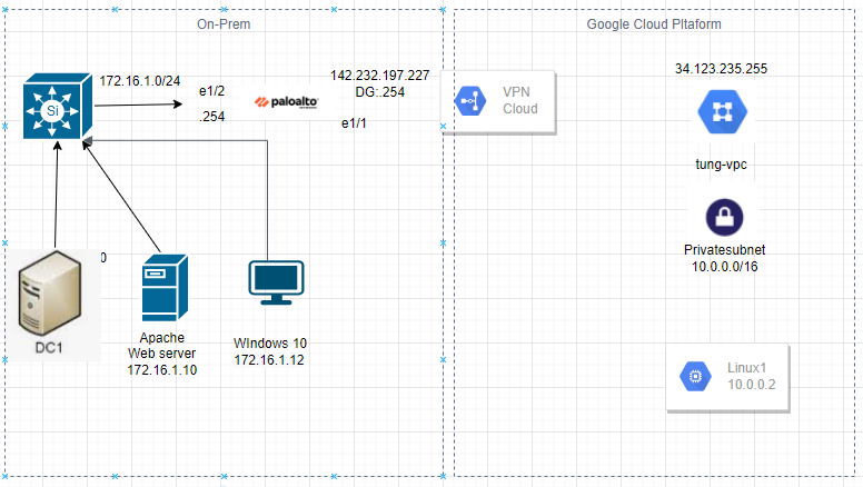
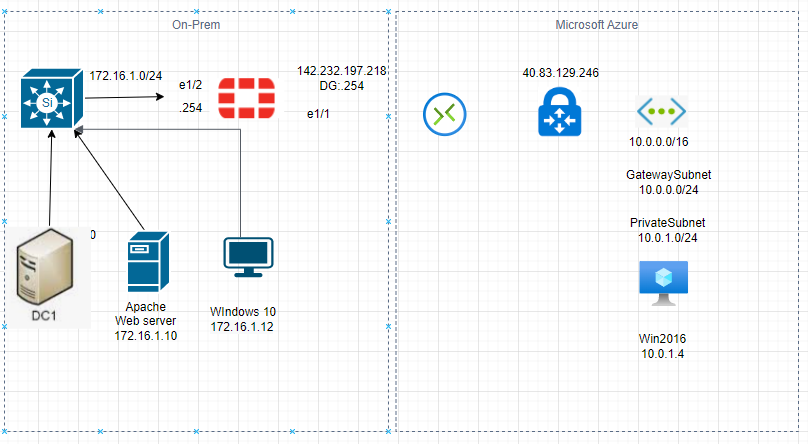
This is a diagram that is used to deploy this lab.

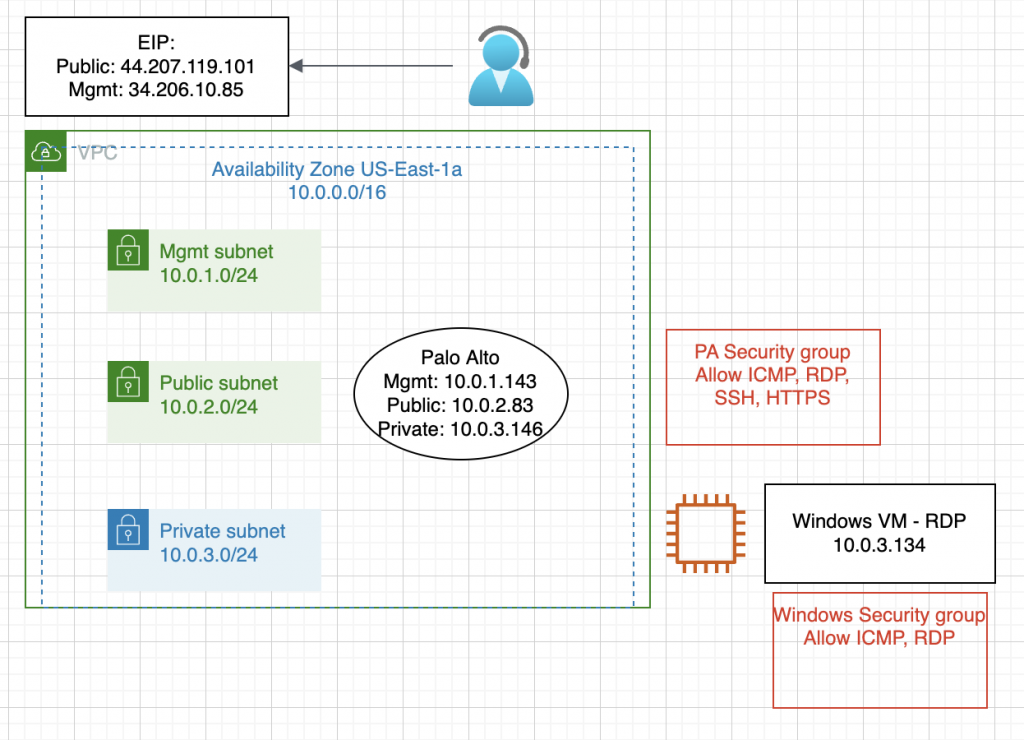
Below are a couple of steps to deploy Palo Alto on AWS

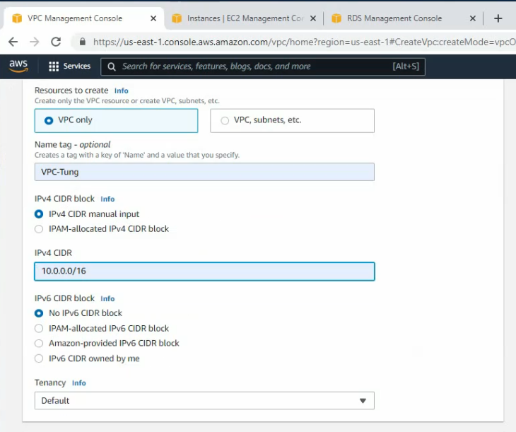
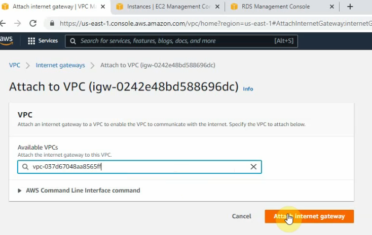
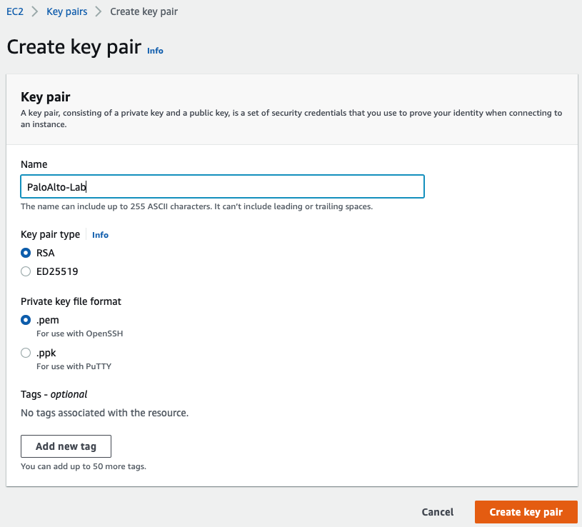
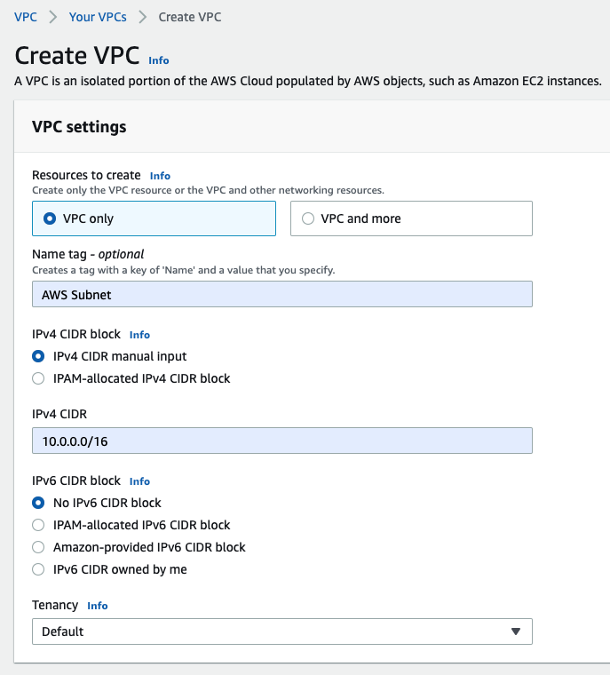
  • Create a key pair, VPC, subnets, Internet Gateway, Route tables
  • Create a Palo Alto instance on AWS
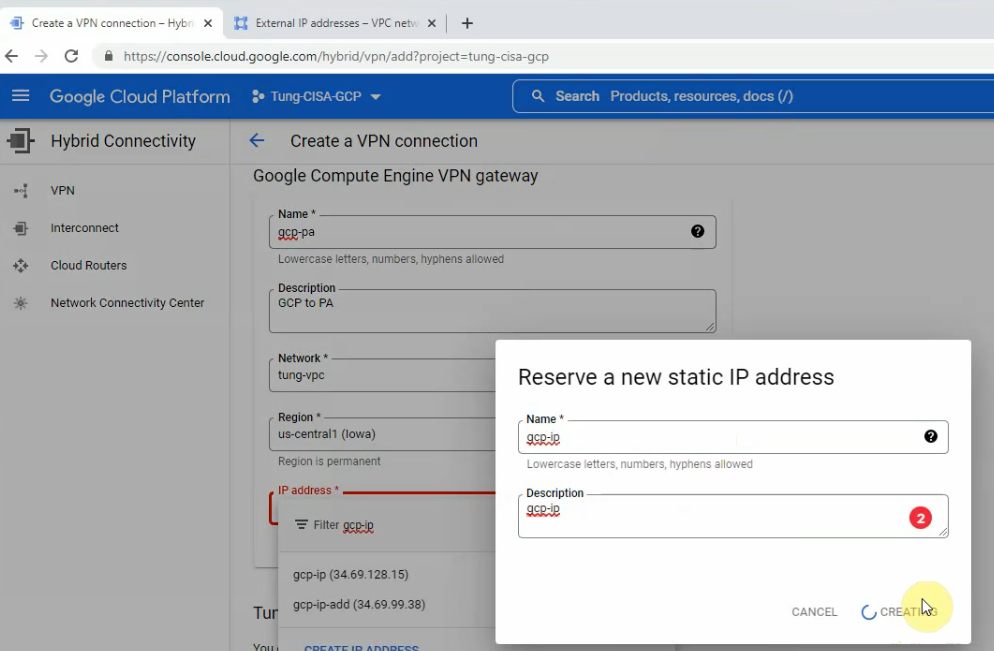
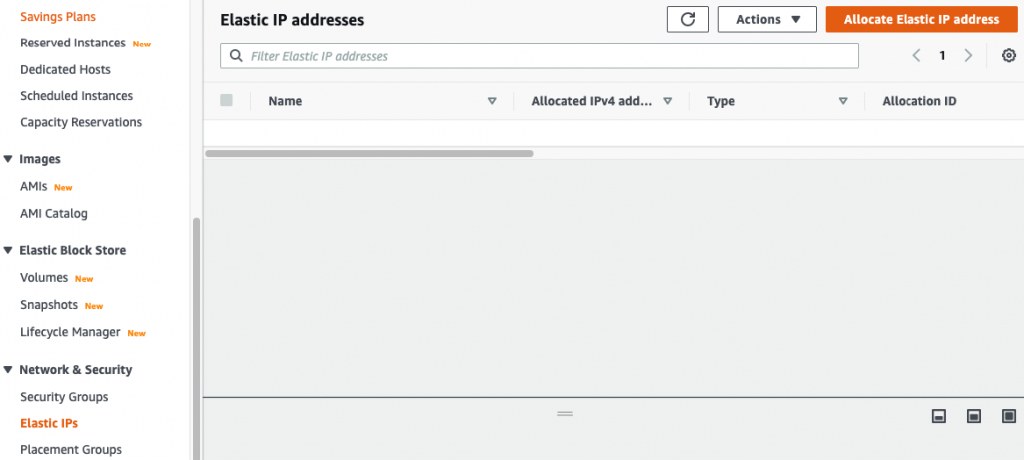
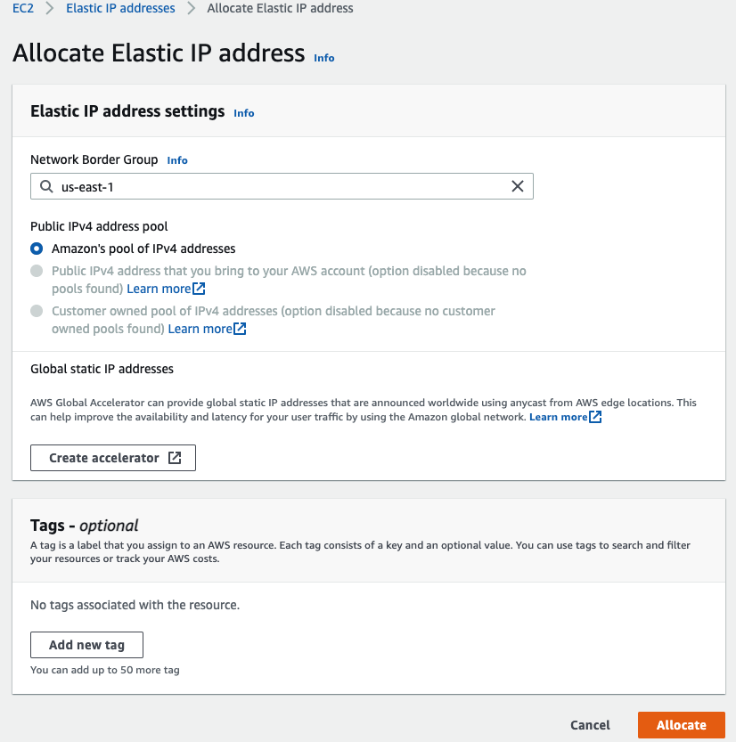
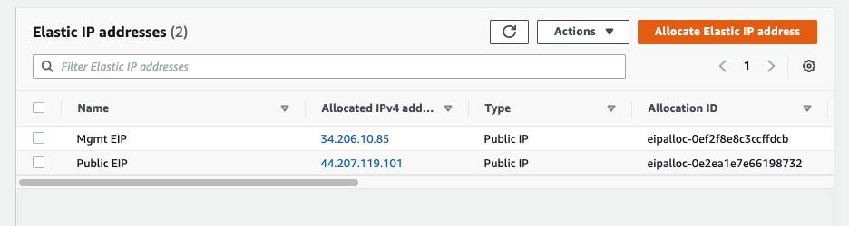
  • Create Elastic IP addresses for Management and Public interface
  • Create a Windows VM on private subnet
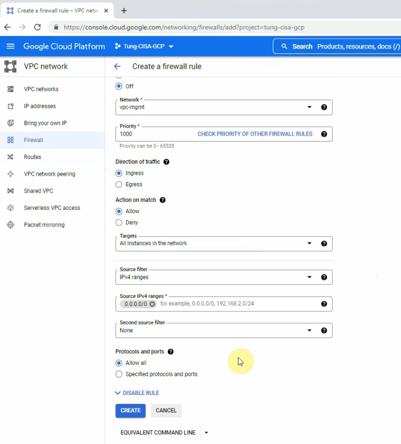
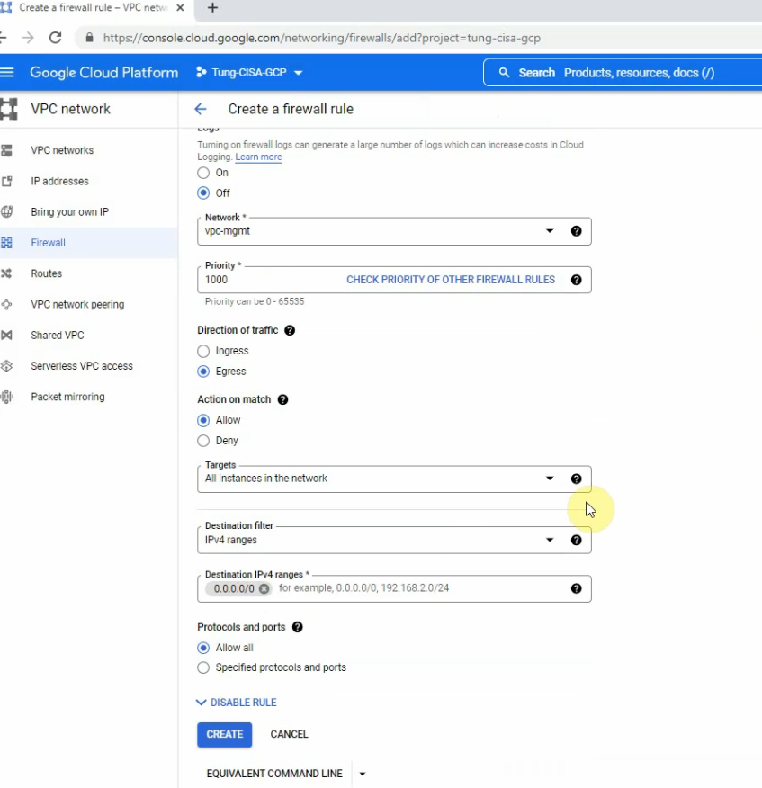
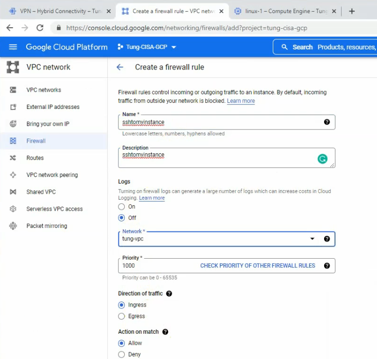
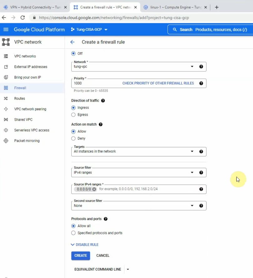
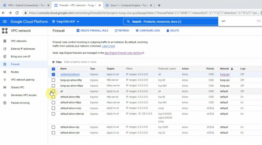
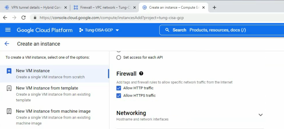
  • Modify Security Group to allow traffic from the Internet to PA and Windows VM
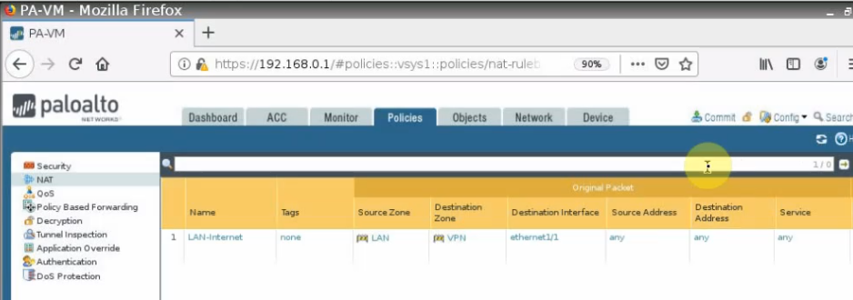
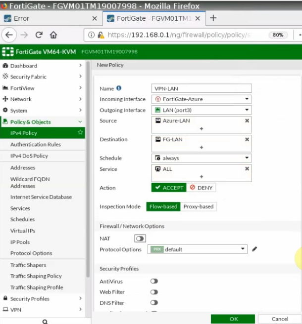
  • Configure a Security Policy, NAT to allow traffic from the Internet to the Windows VM via RDP
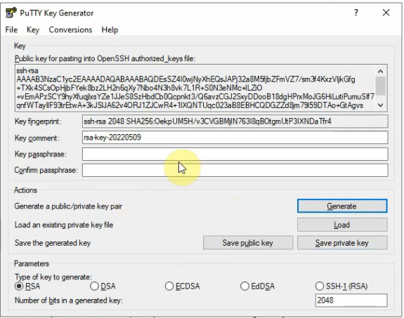
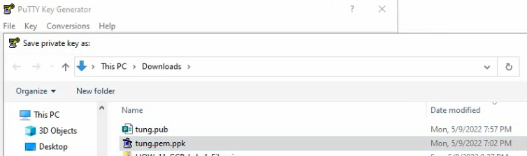
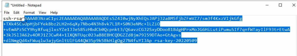
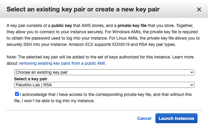
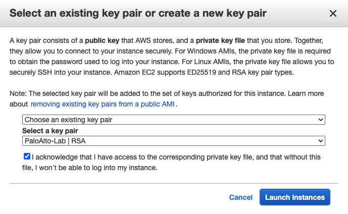
Create a key pair.

Create a VPC.
Create a management subnet.

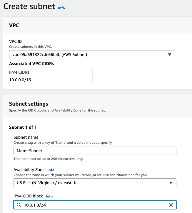
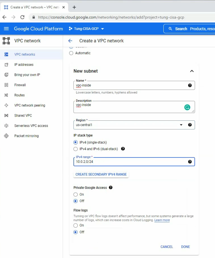
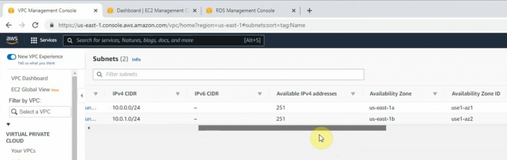
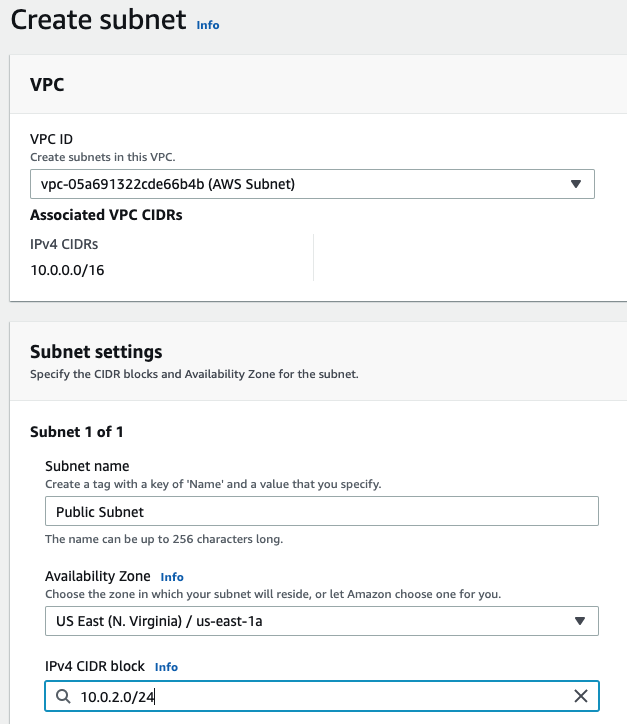
Create a Public subnet on availability zone US-East-1a. I got an error that I cannot create a Palo Alto if my VPC is randomly used US-East-1e.

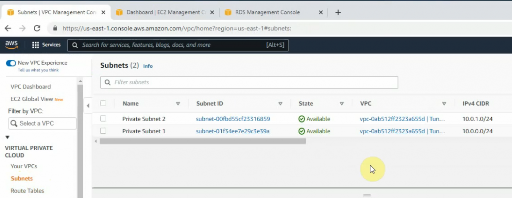
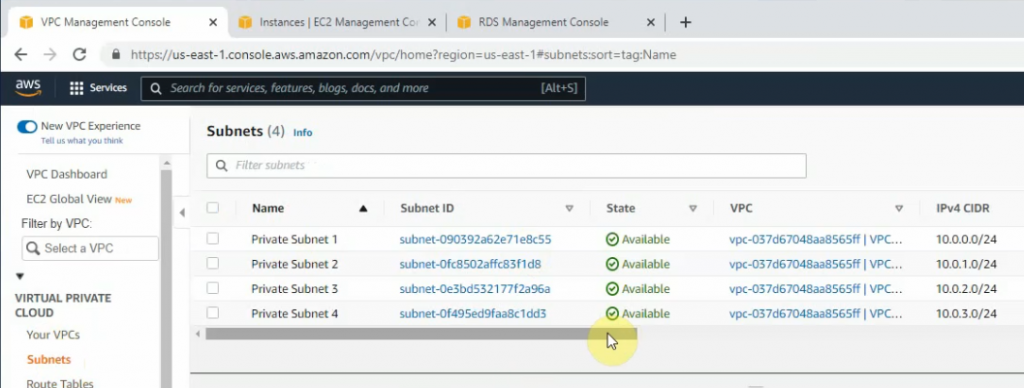
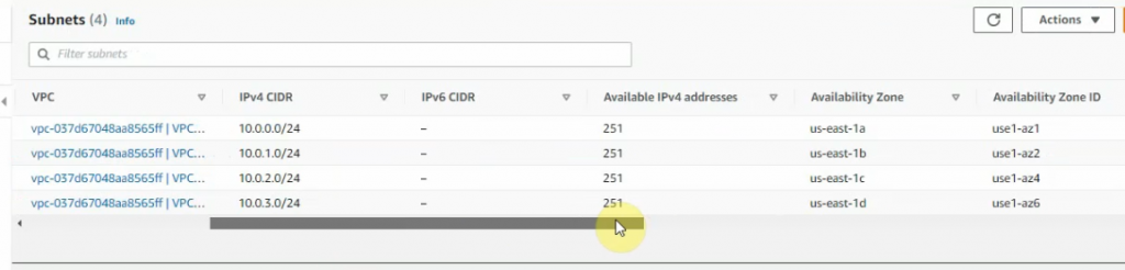
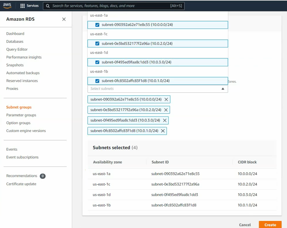
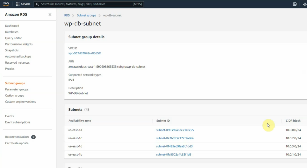
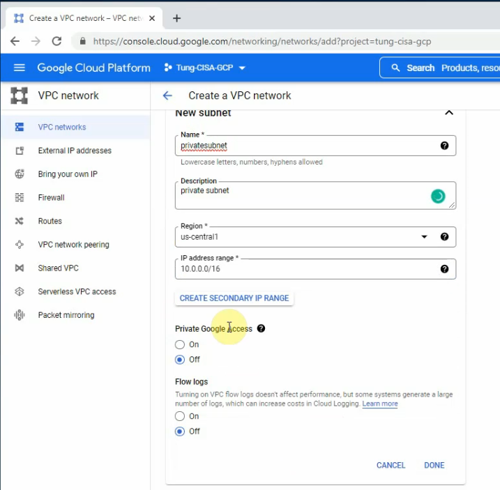
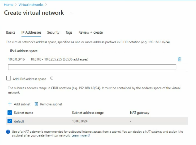
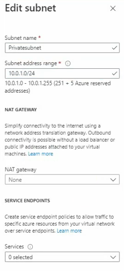
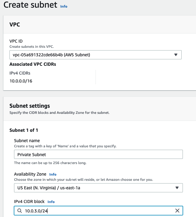
Create a Private subnet.

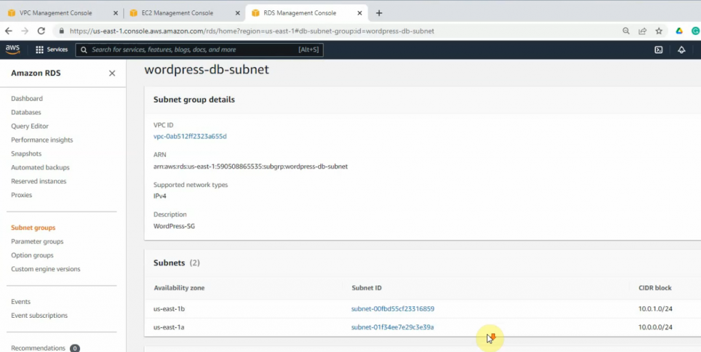
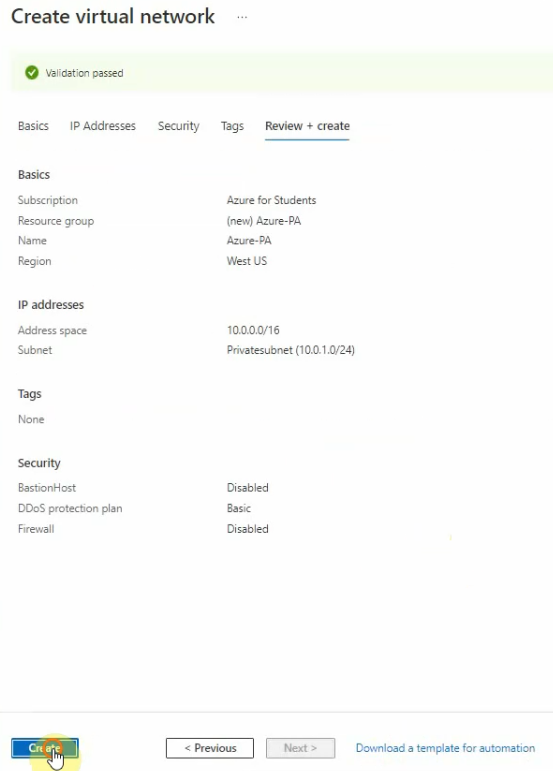
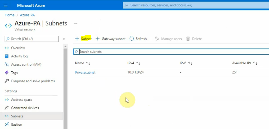
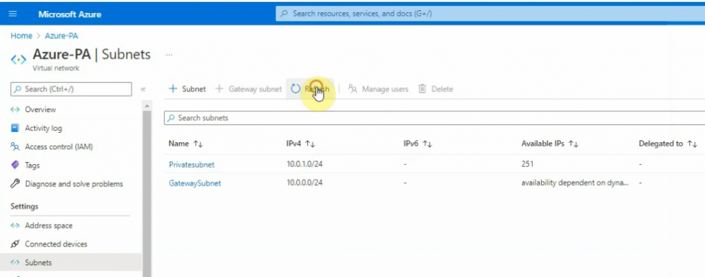
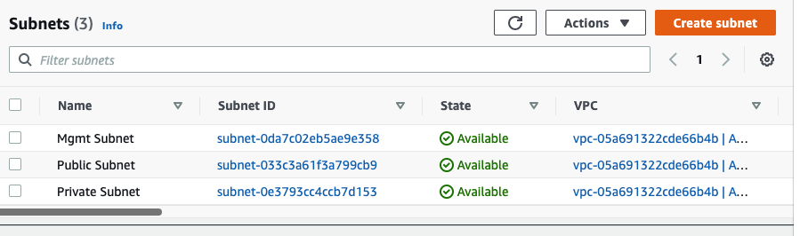
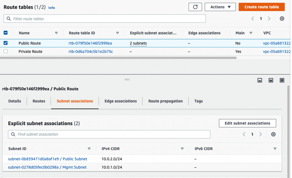
There are 3 subnets on AWS Subnet VPC.

Create a Internet Gateway and attach it into your VPC.
Rename Route table to Private Route

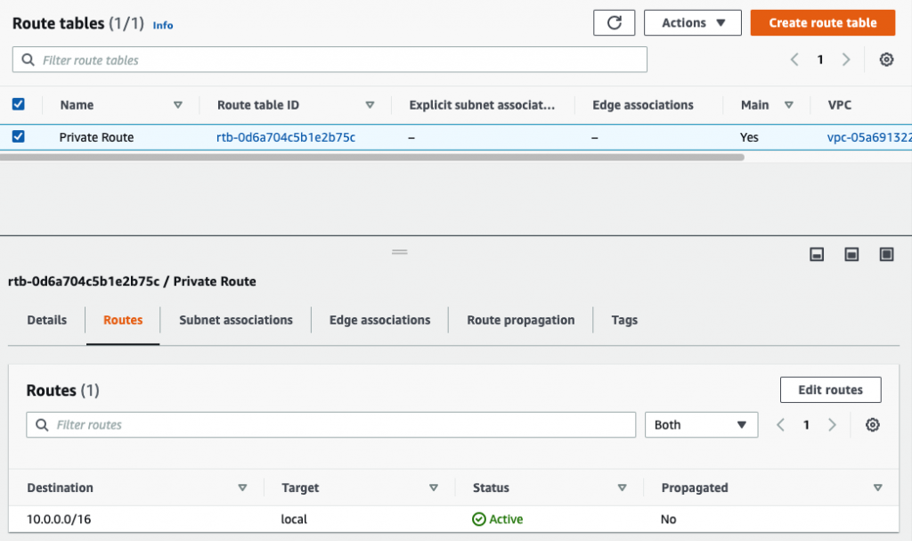
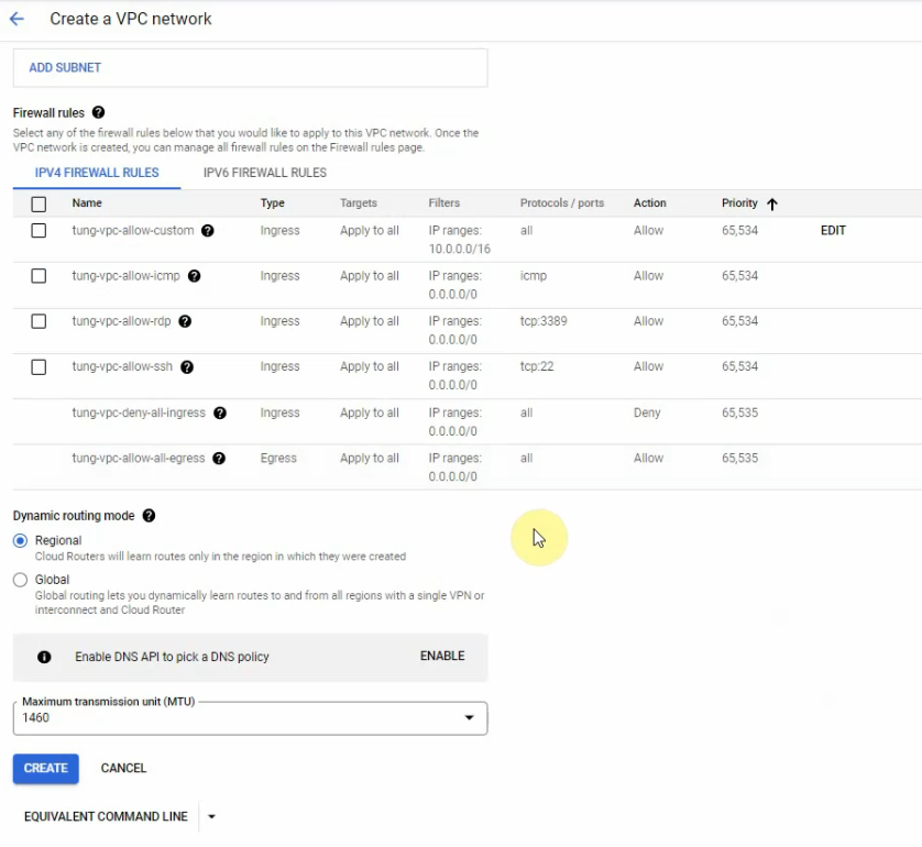
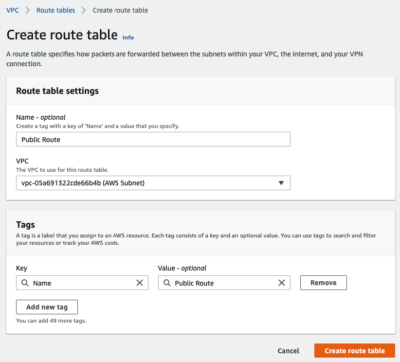
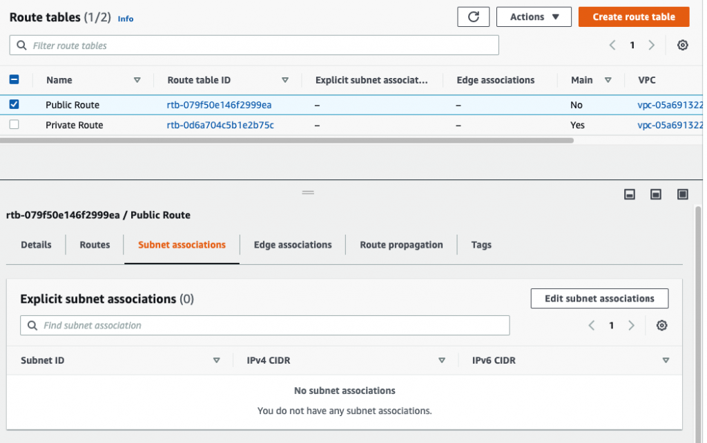
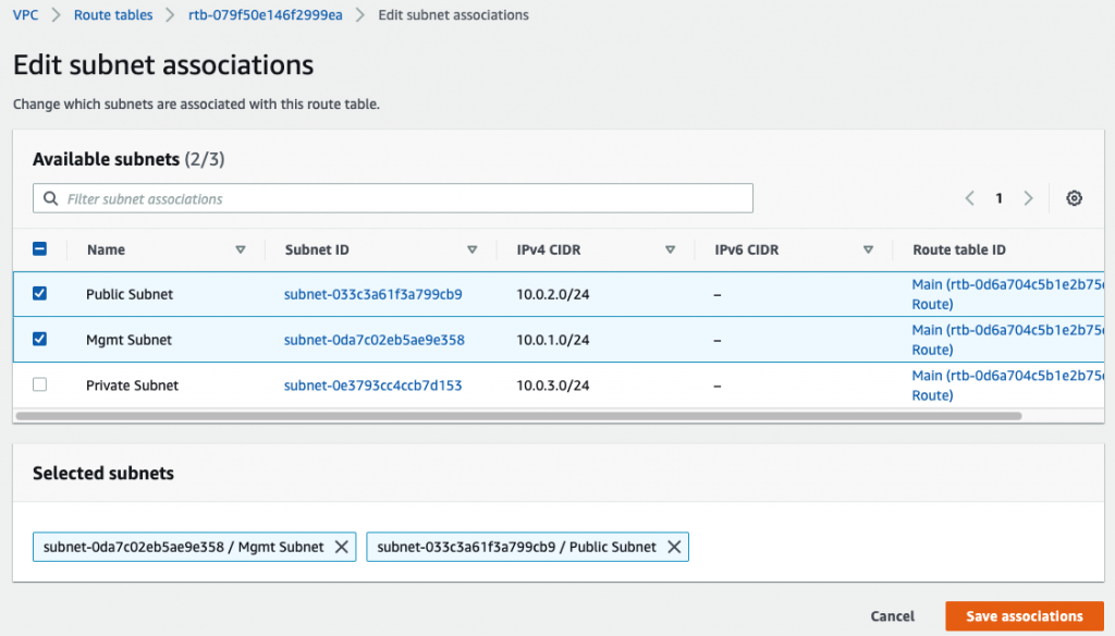
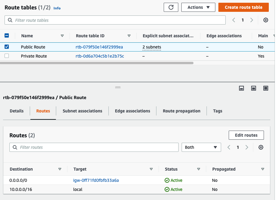
Create a Public Route table.

Associate Management and Public Subnet to Public Route table.

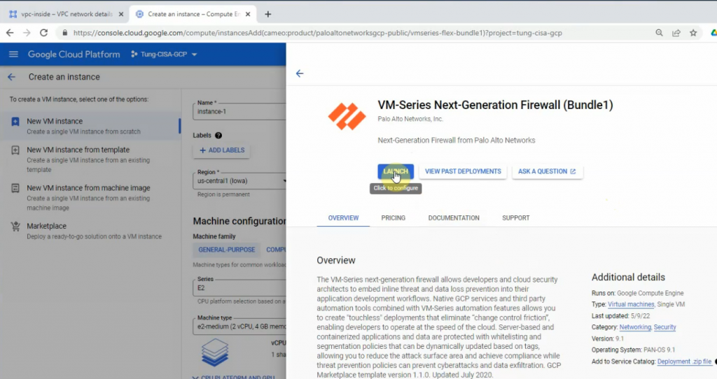
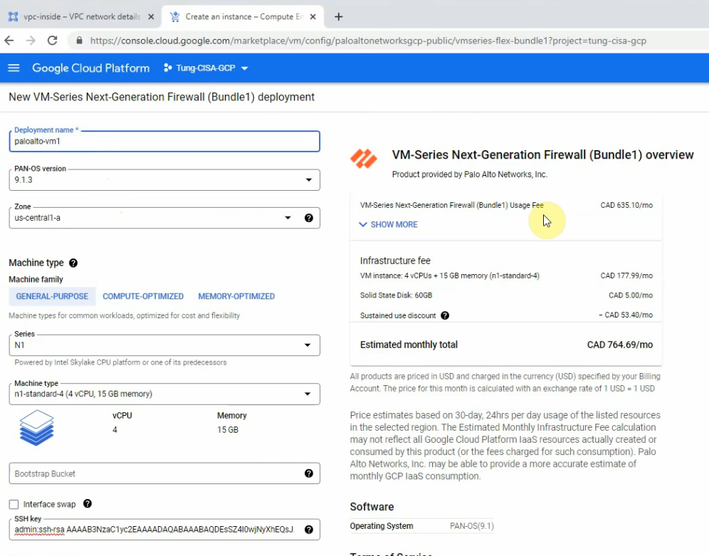
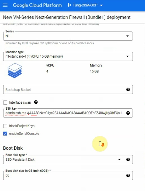
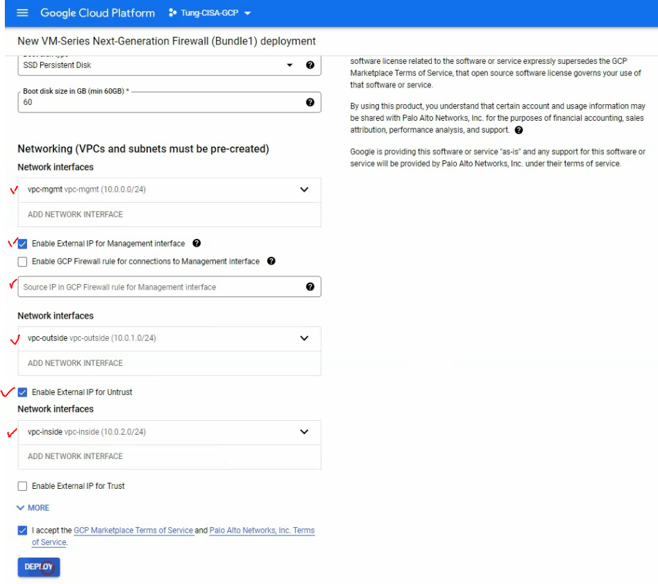
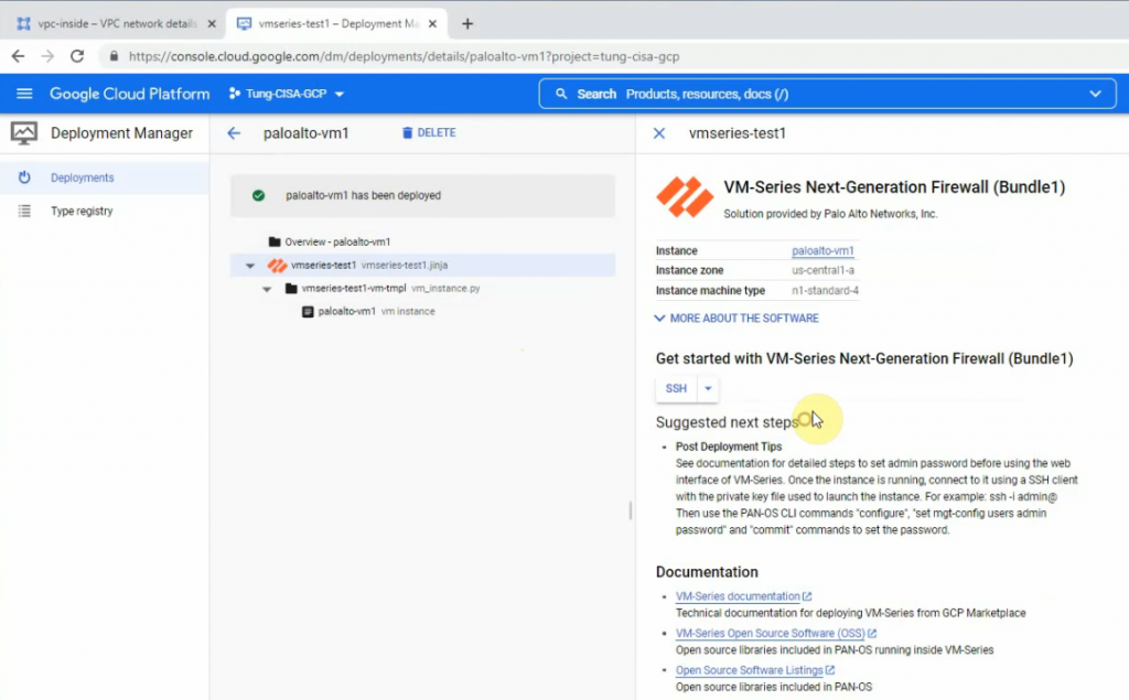
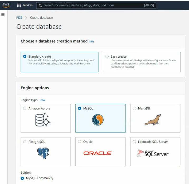
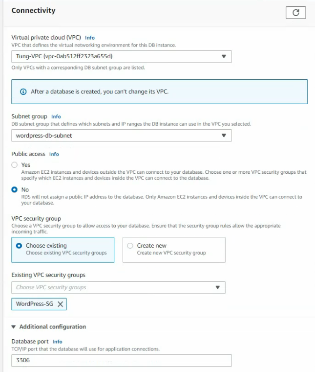
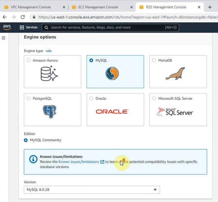
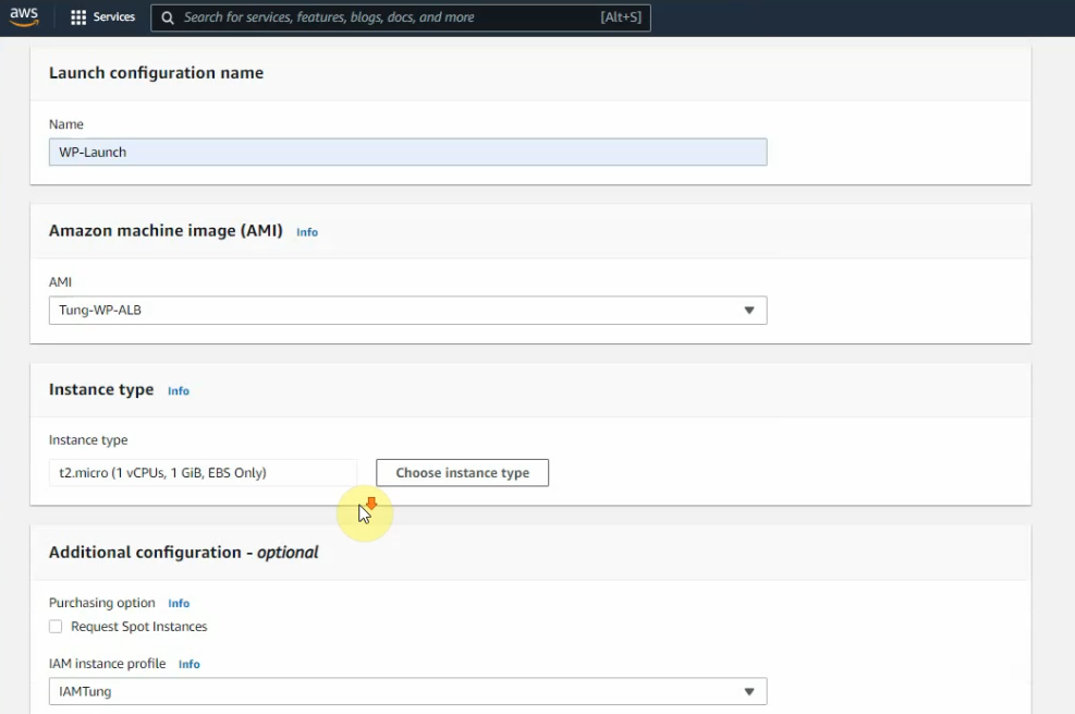
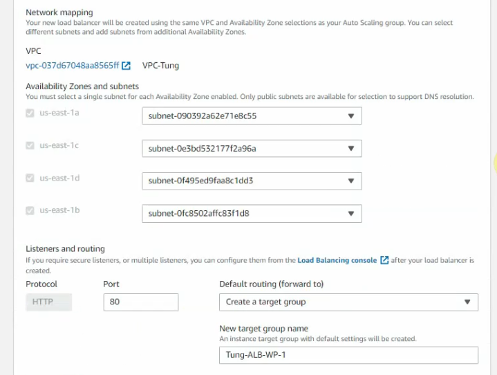
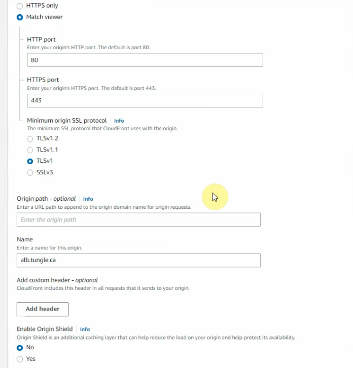
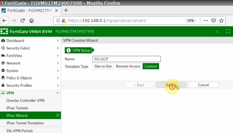
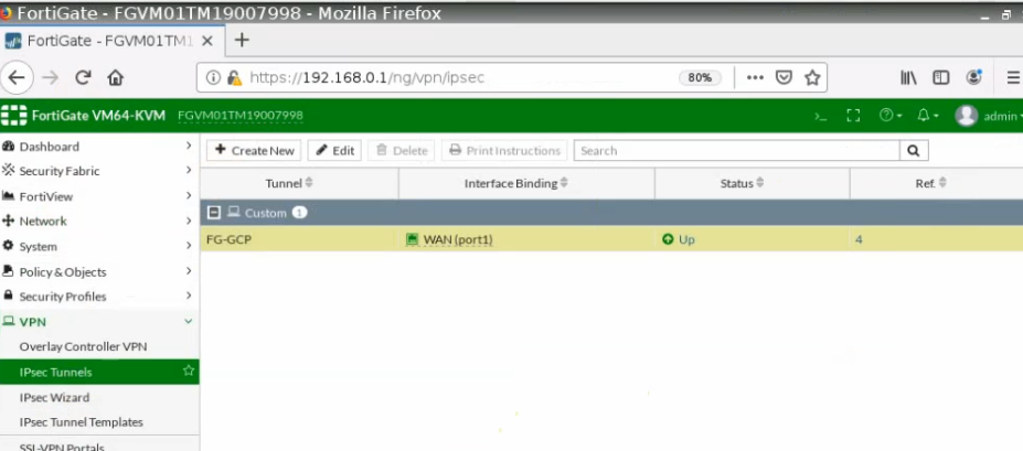
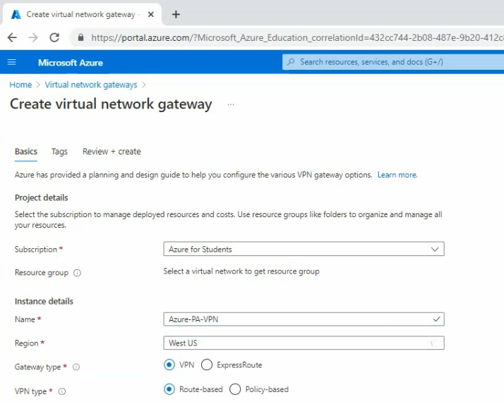
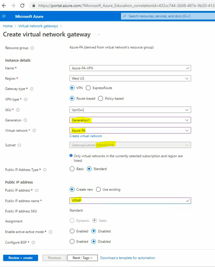
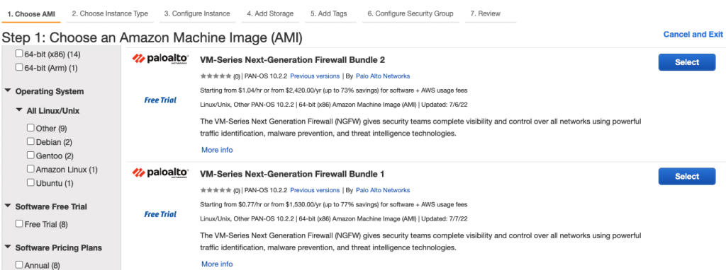
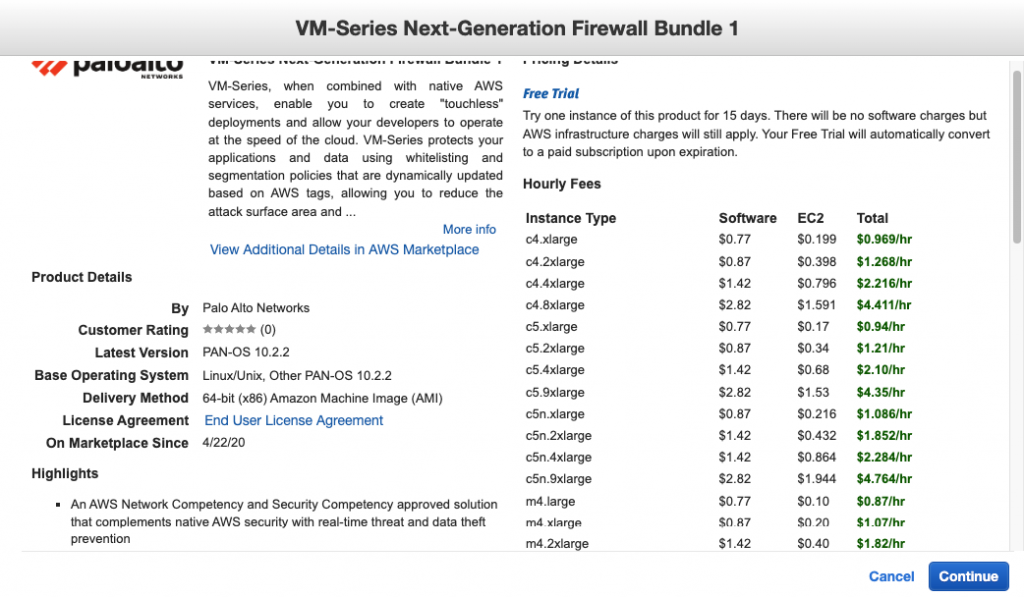
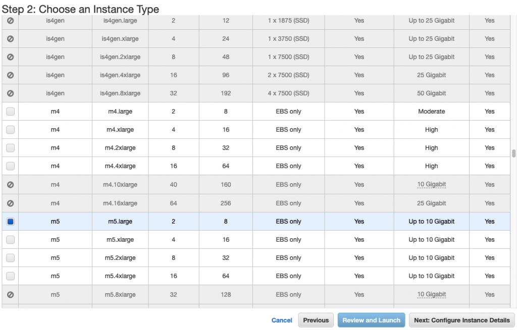
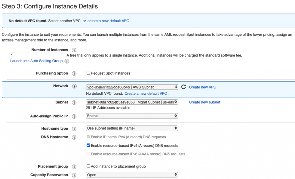
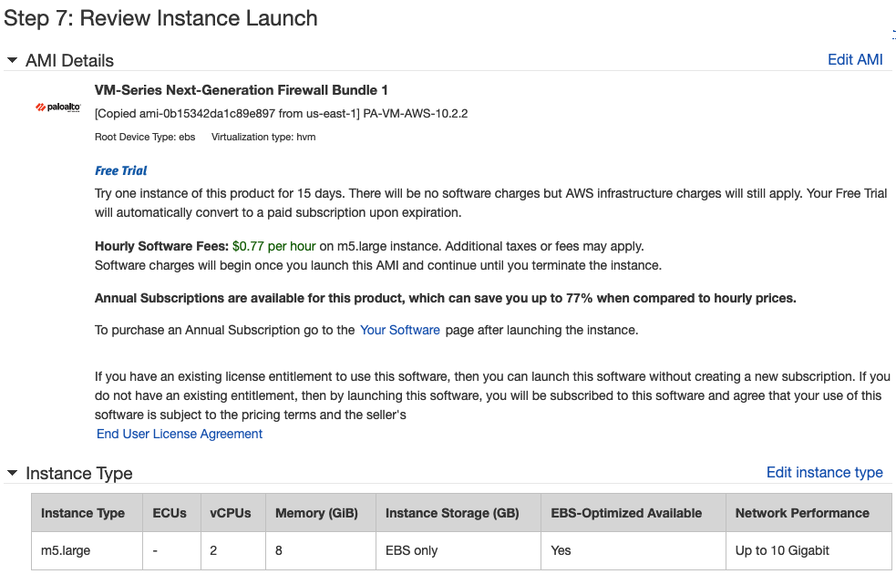
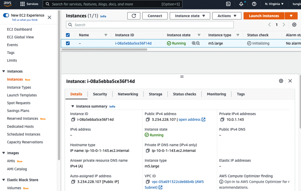
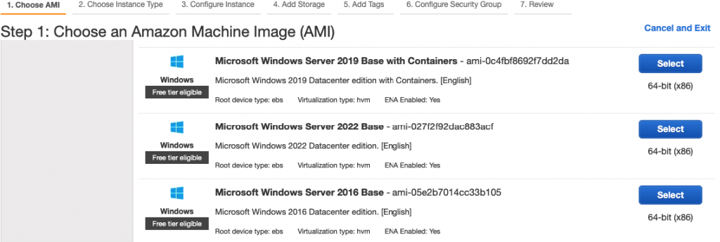
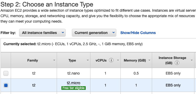
Launch a Palo Alto Firewall on AWS.

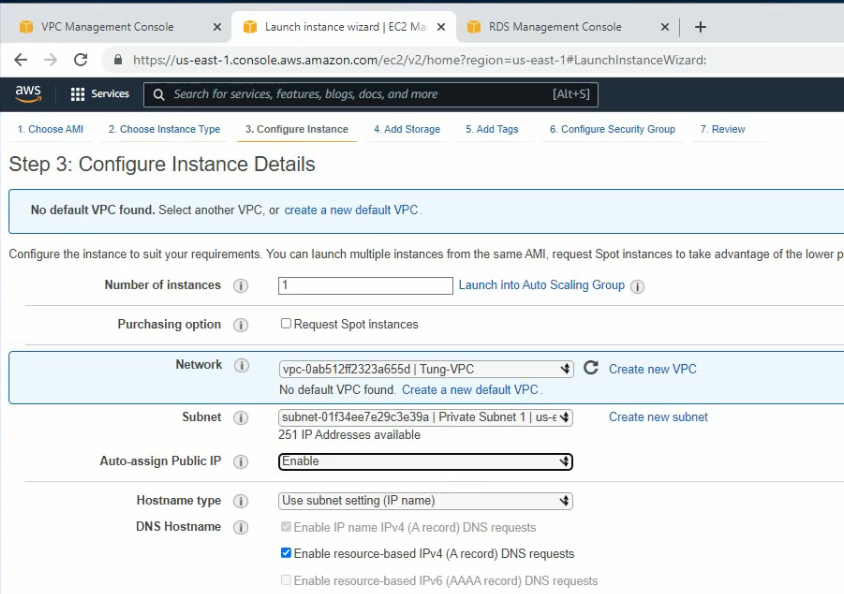
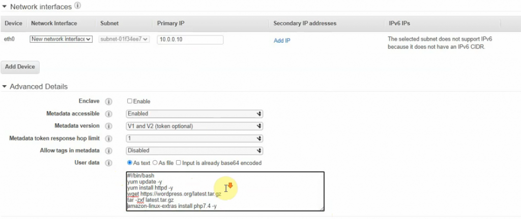
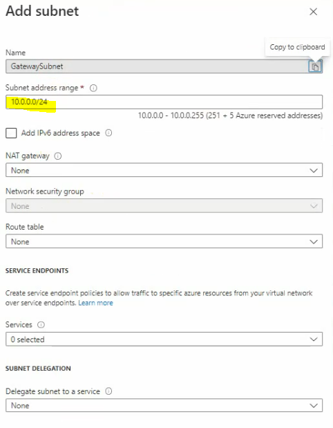
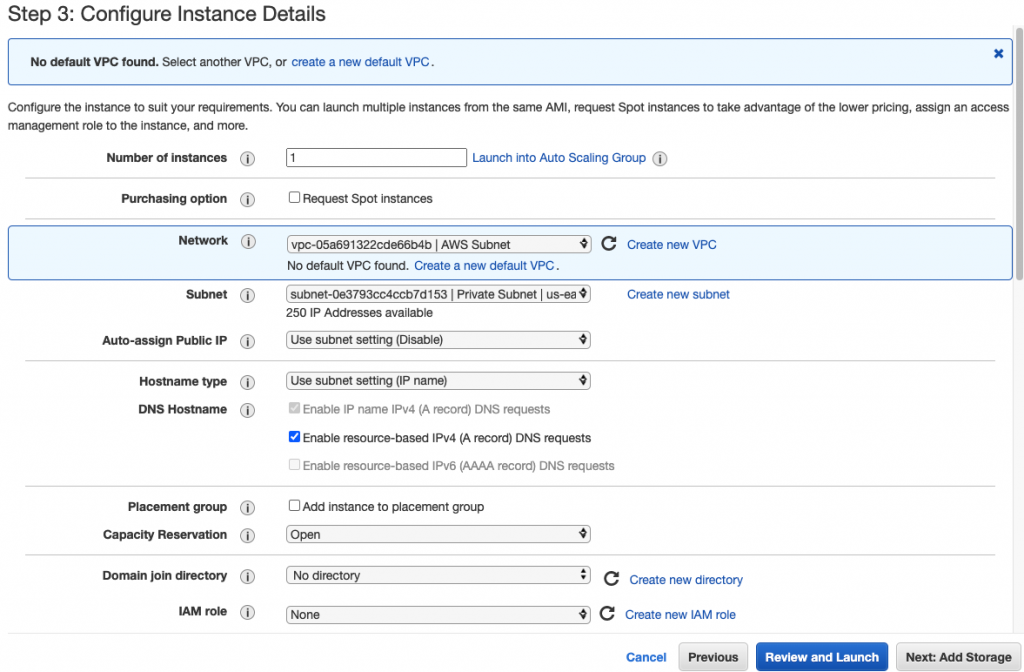
Select “Management Subnet” in the Subnet setting.

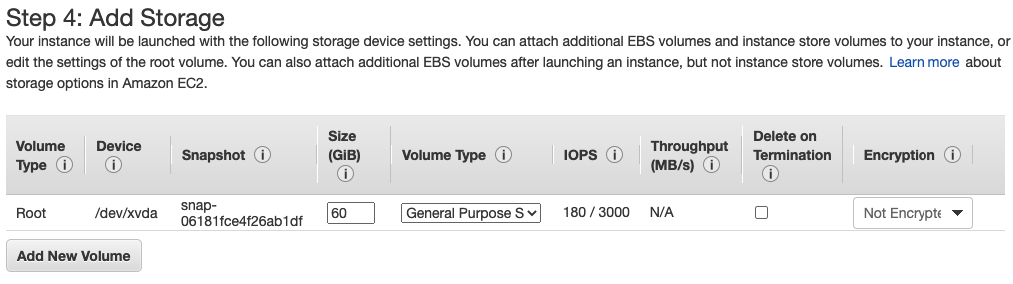
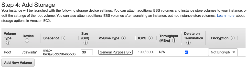
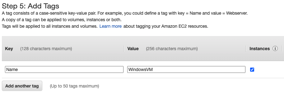
Leave “Add Storage” and Tags as default.

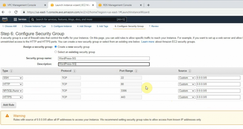
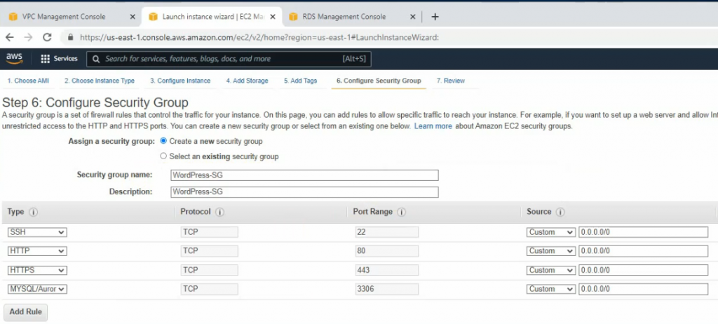
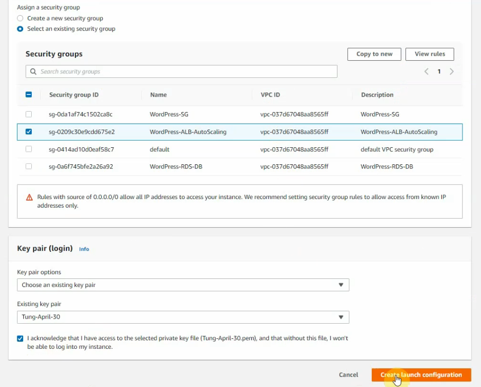
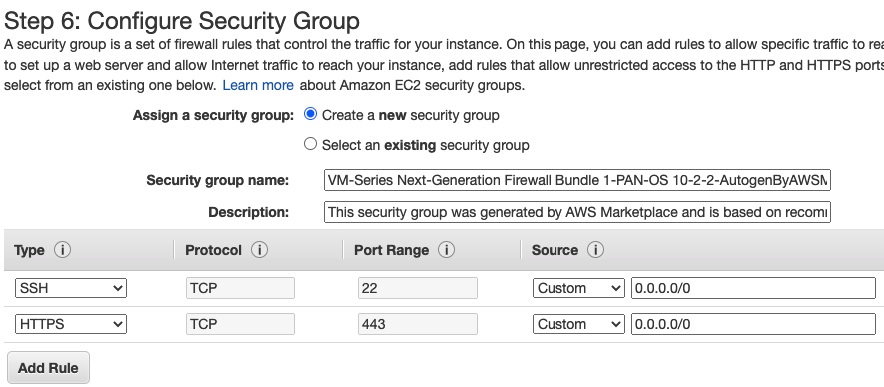
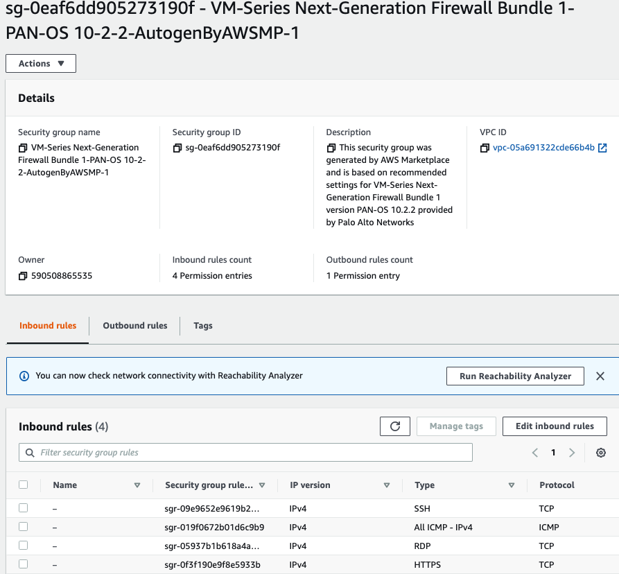
Use a Security Group that has been generated automatically when creating the PA VM.

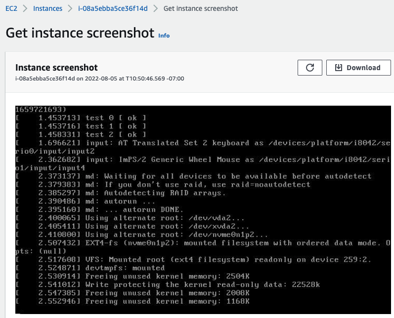
Actions – Monitor – get instance screenshot.

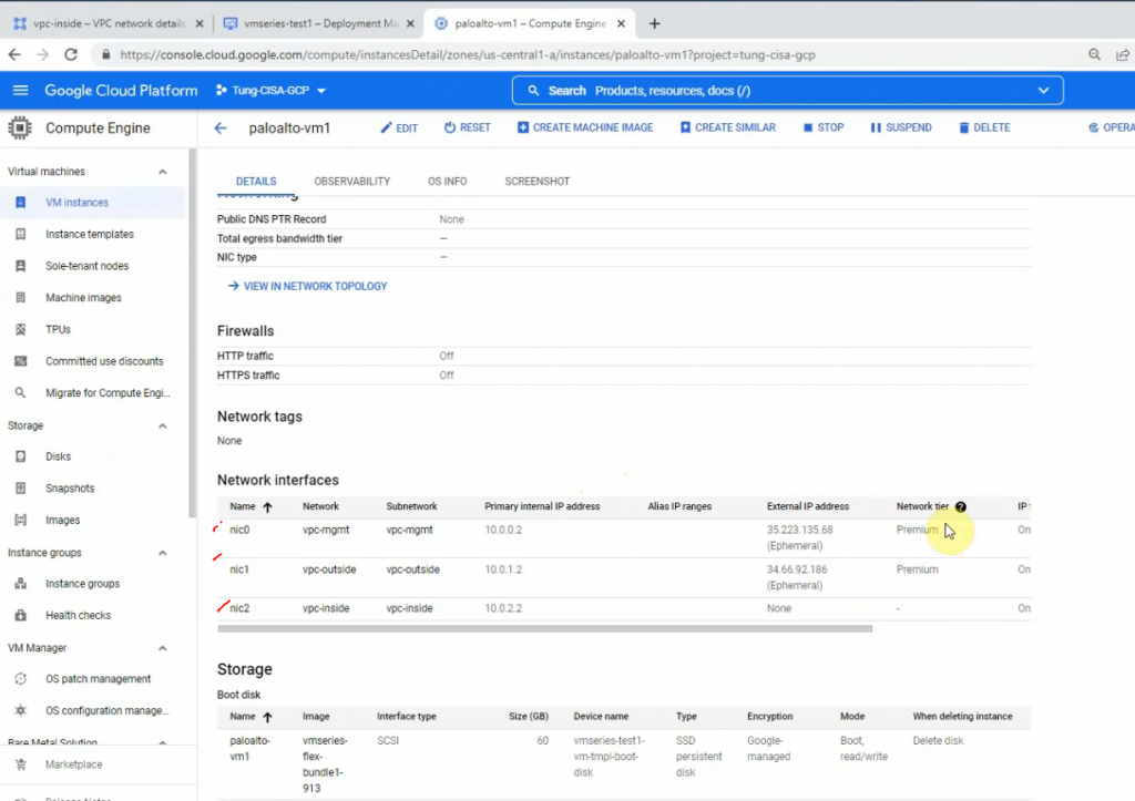
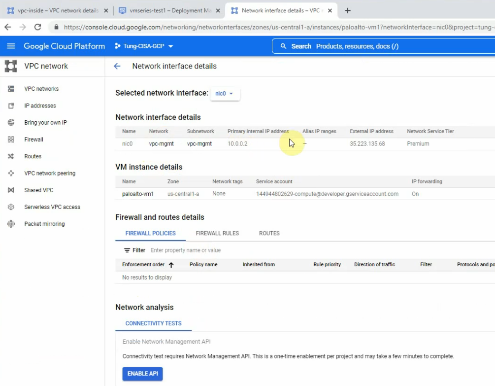
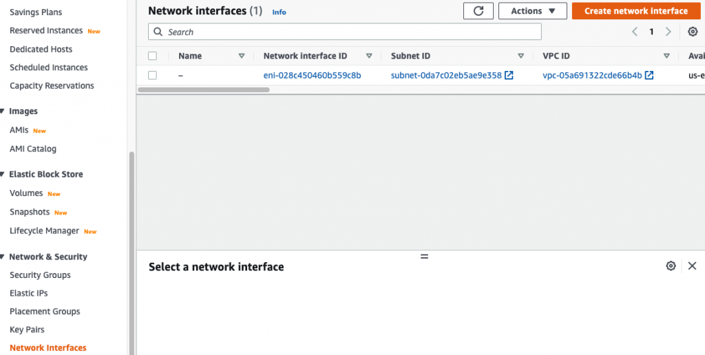
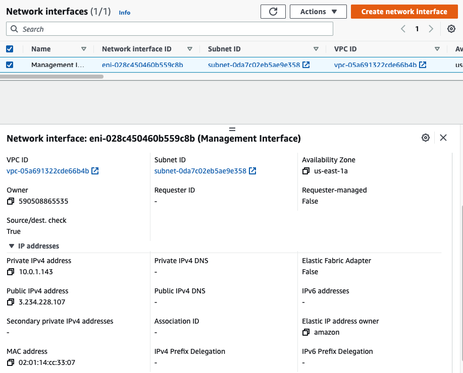
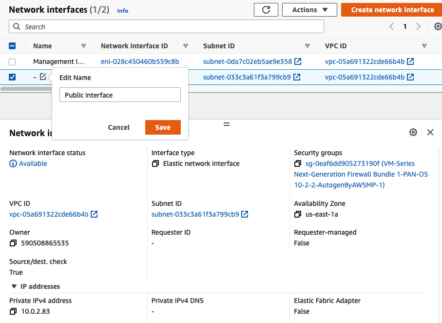
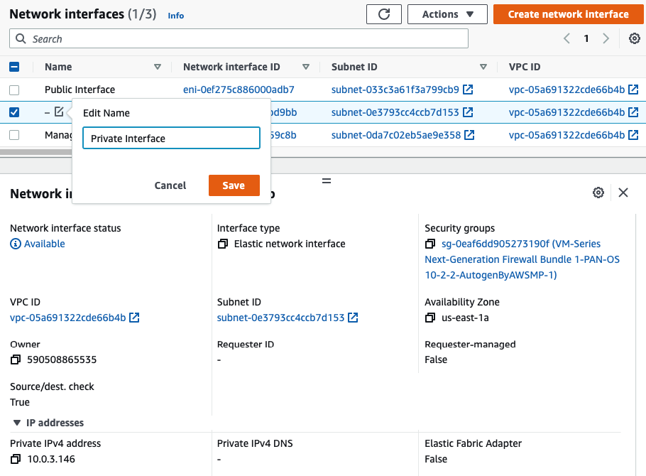
Go to EC2 – Network interfaces. Rename a name of the “-” to “Management interface”.

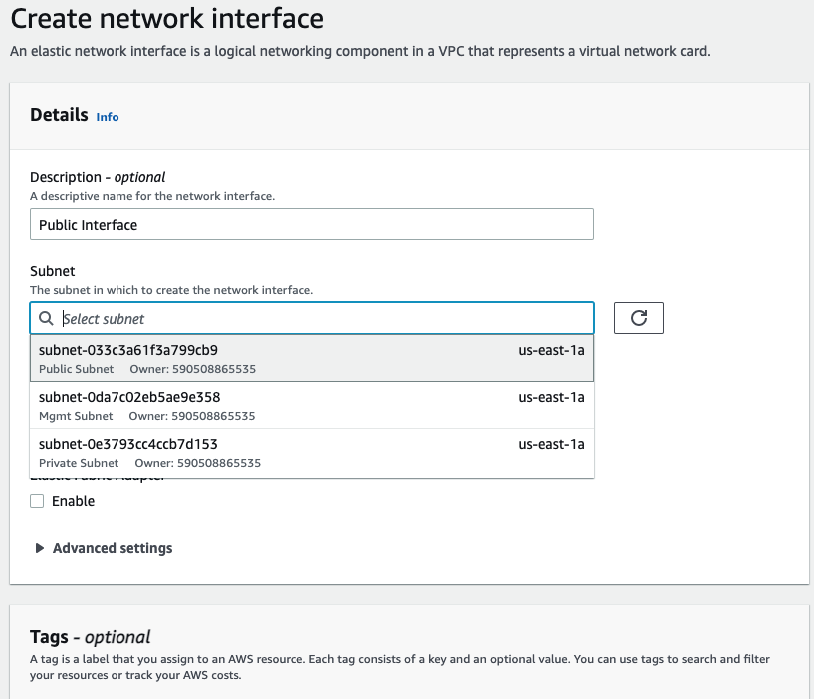
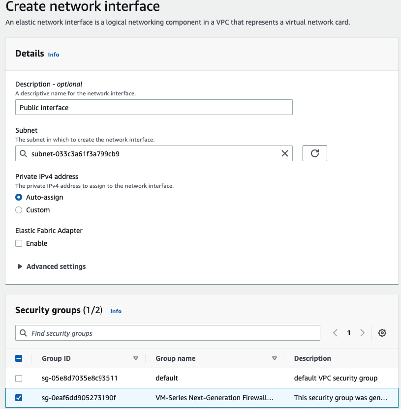
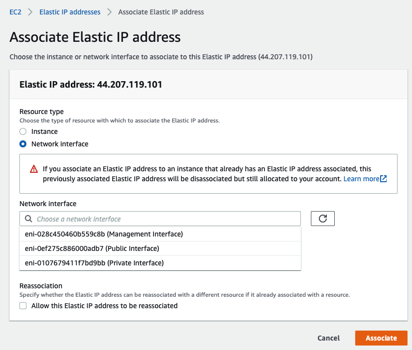
Create a Public interface of PA and link it to the “Public Subnet”.

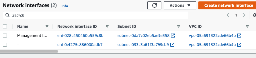
Rename a name of the “-” to “Public interface”.

Attach it into PA.

Create a Private interface of PA and link it to the “Private Subnet”.

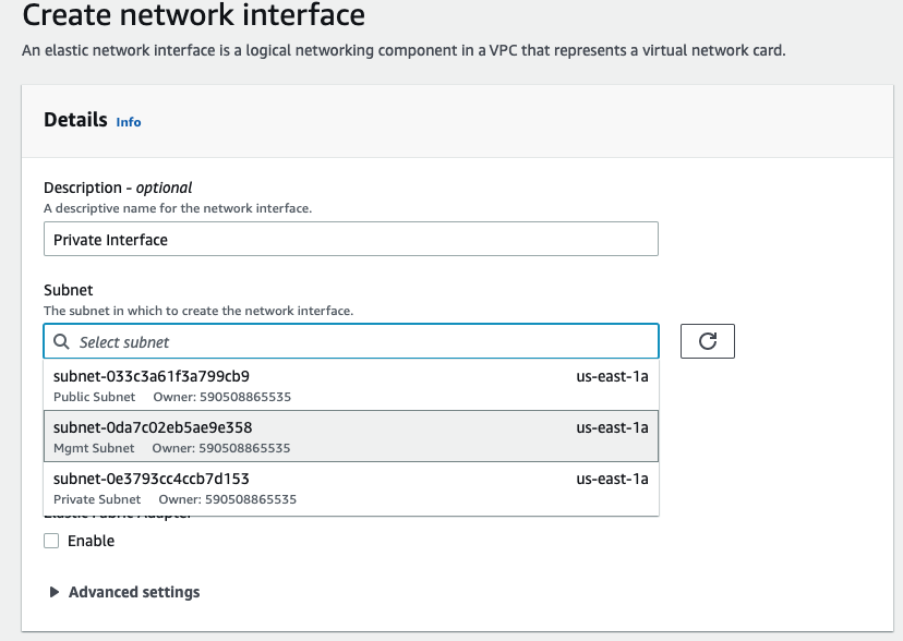
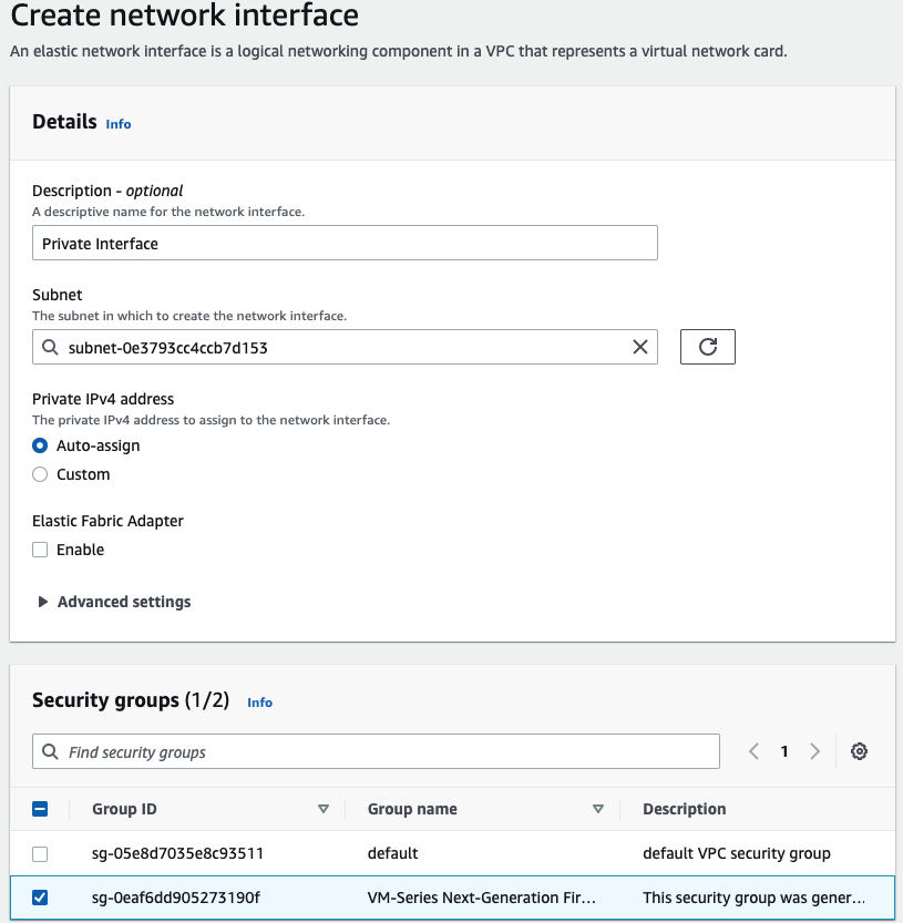
Rename a name of the “-” to “Private interface”.

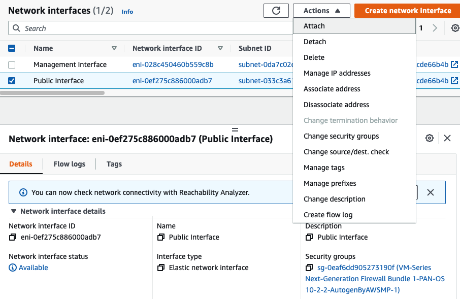
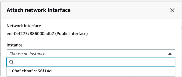
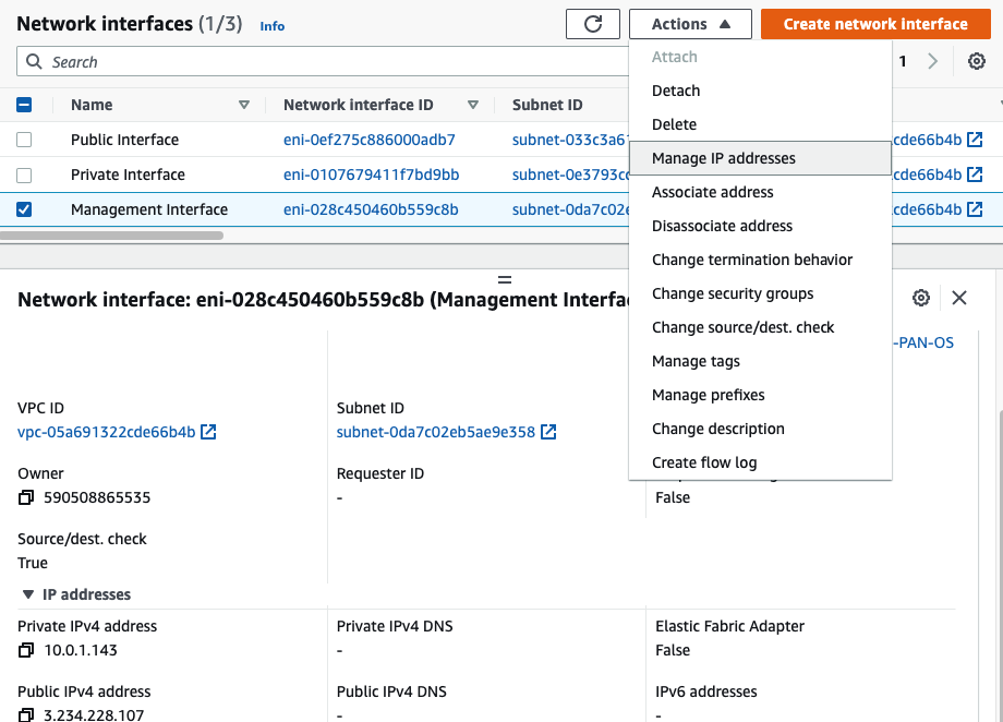
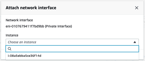
Attach the Private interface into PA.

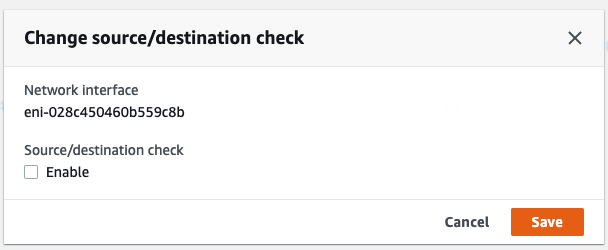
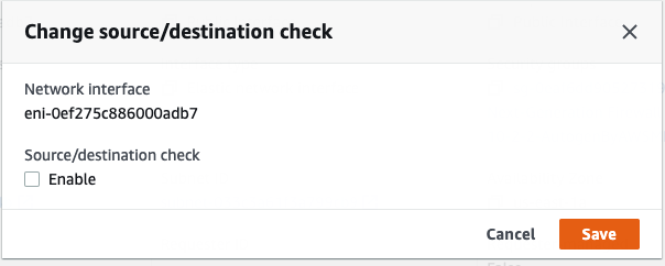
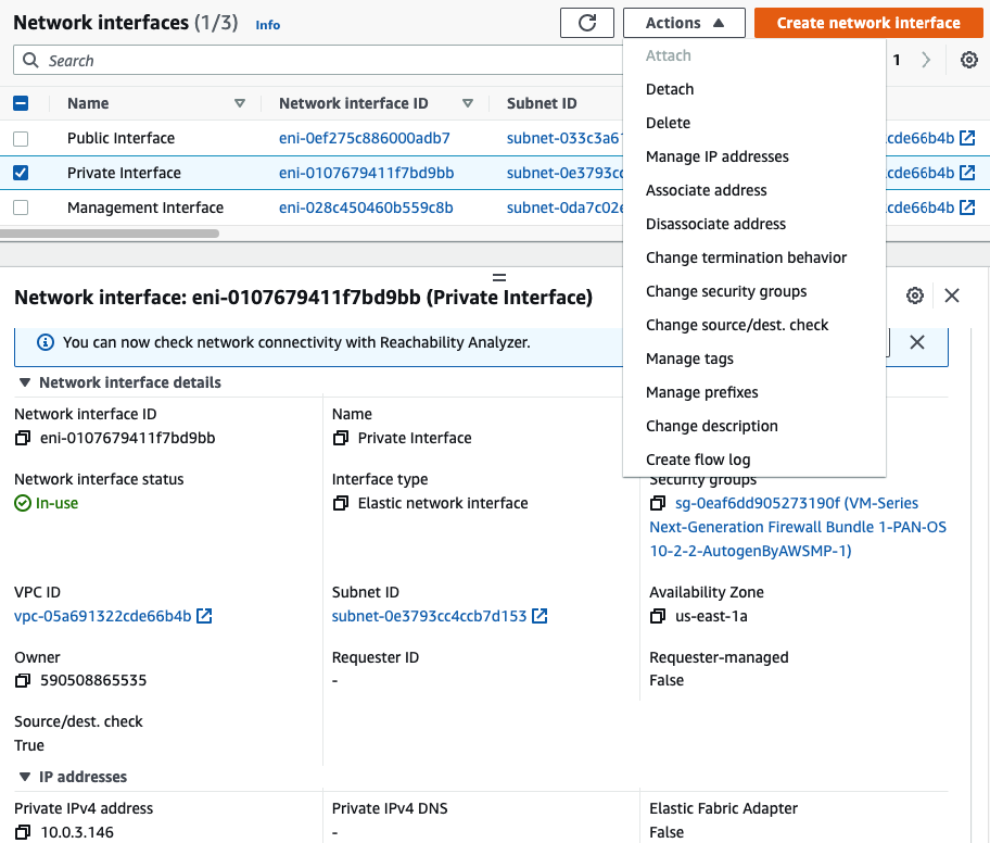
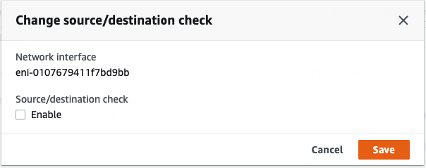
Disable “Change source/dest. check” in all interfaces.

Assign two Elastic IP addresses for Public interface.
Associate EIP to Public interface.

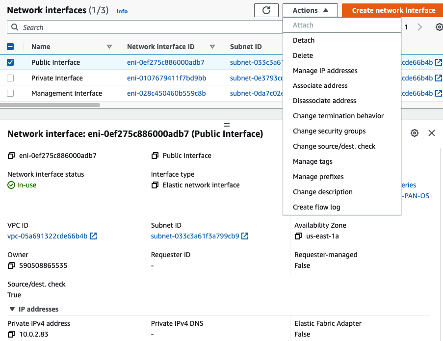
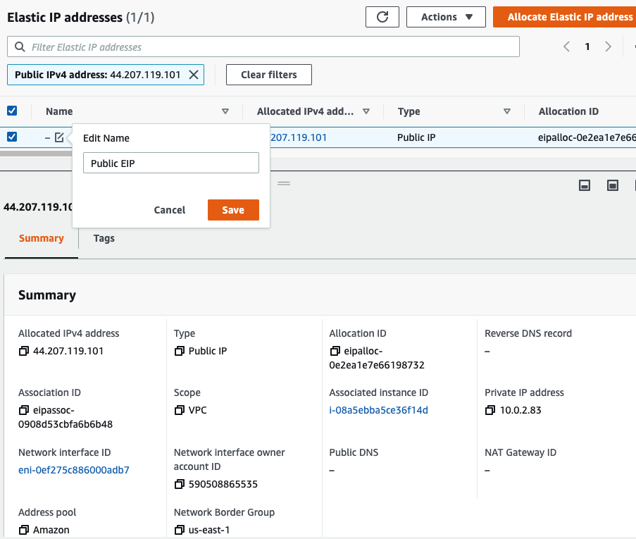
Select “Public interface”

Rename “-” to Public EIP.

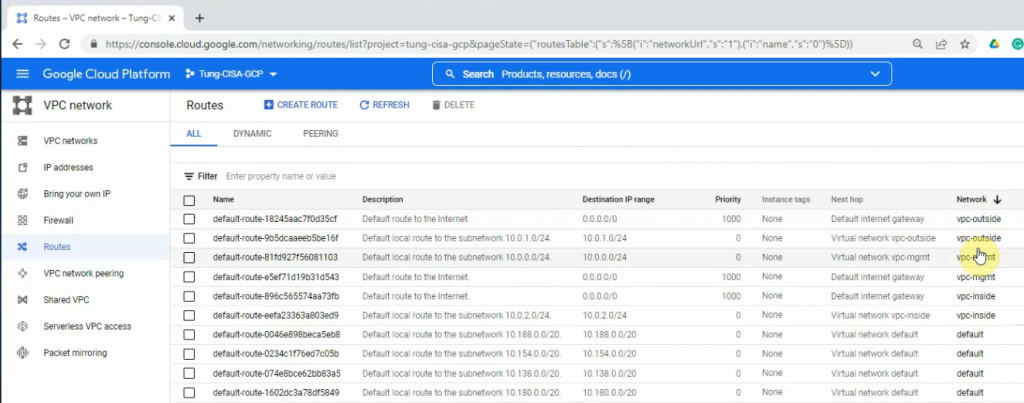
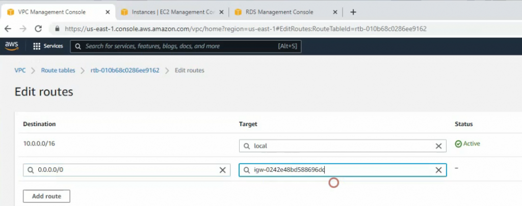
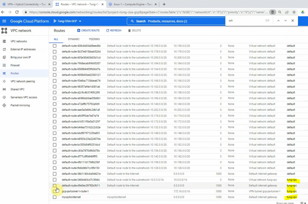
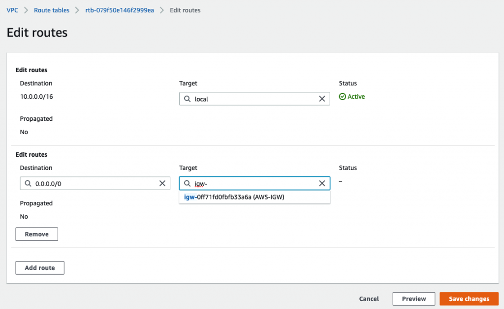
Back to Route table,

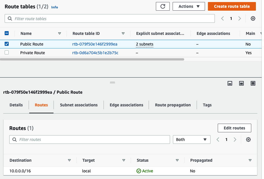
Create a default route via Internet Gateway.

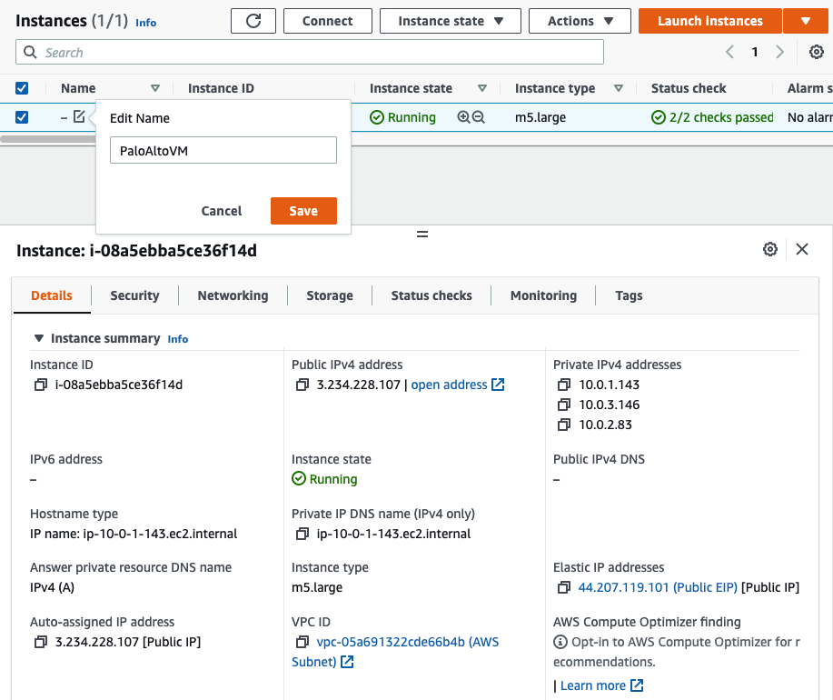
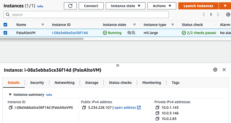
Back to PA instance, rename it into PaloAltoVM.

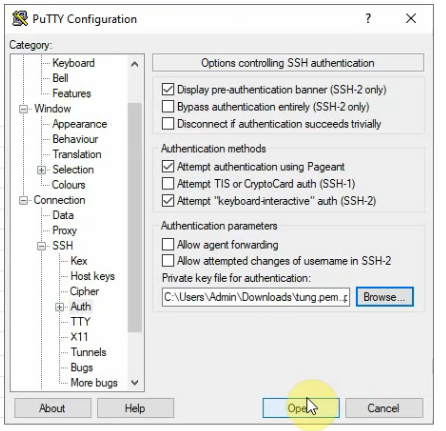
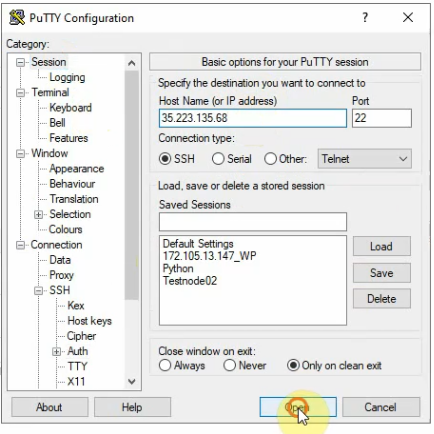
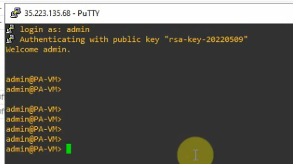
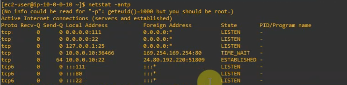
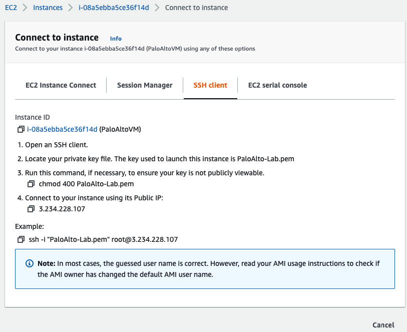
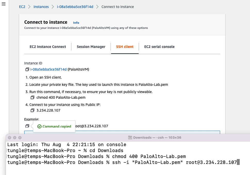
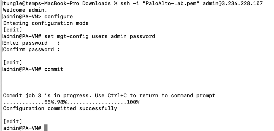
Access SSH to Palo Alto instance.

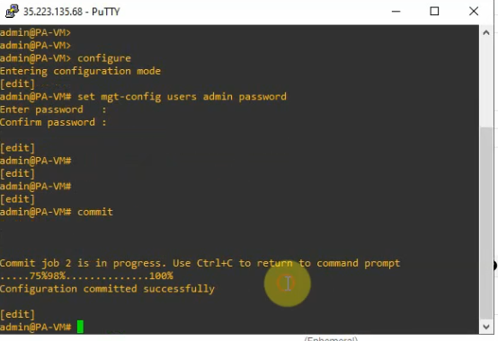
Change password of user admin.

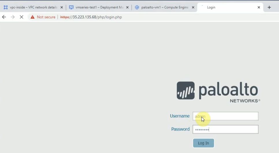
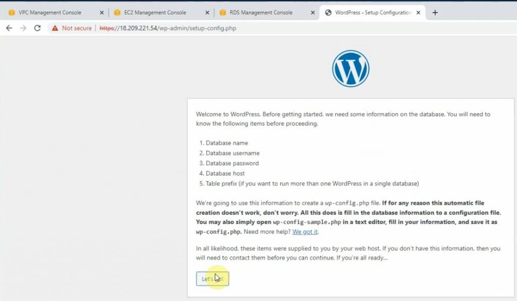
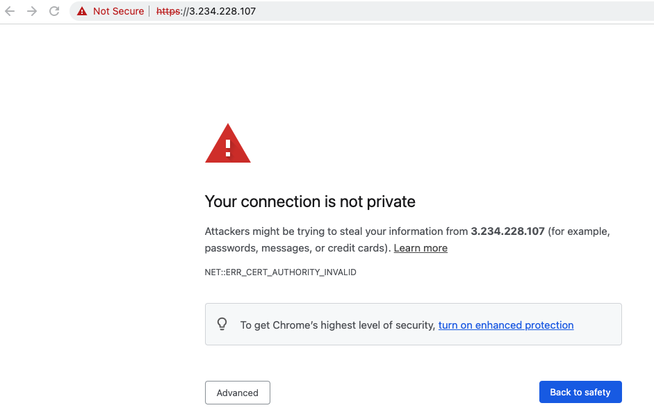
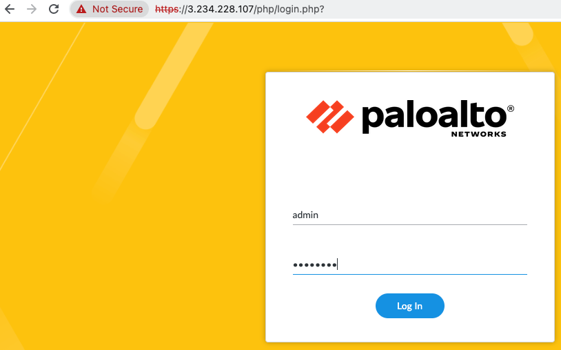
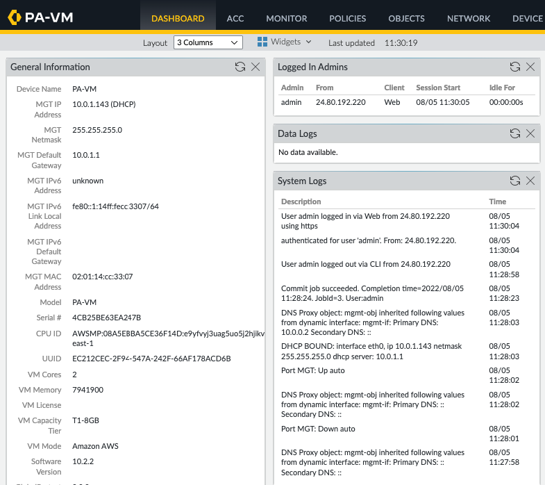
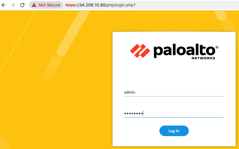
Log into PA via a web browser.

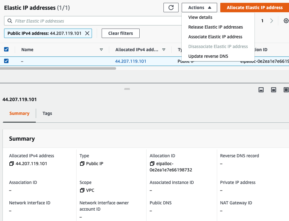
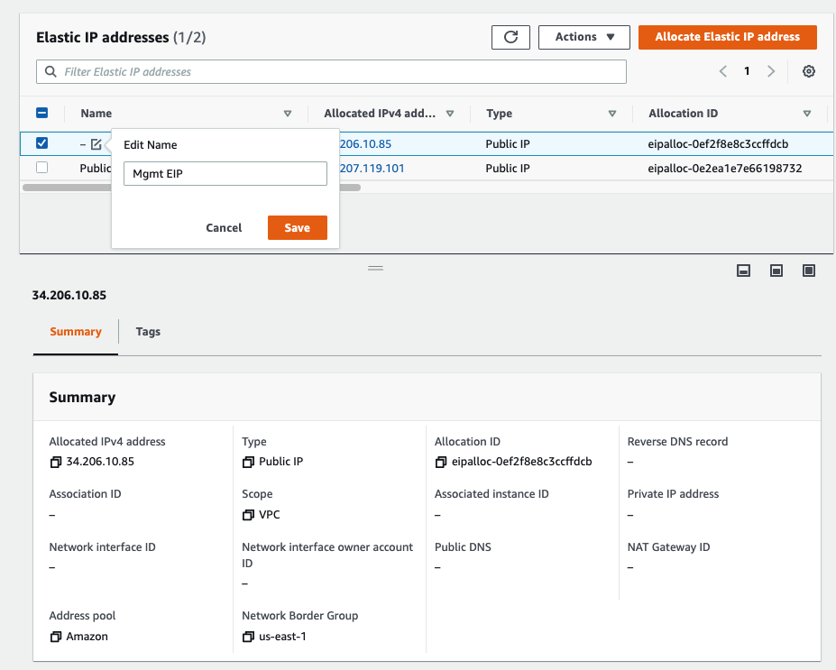
Back to EC2 – EIP. Assign a permanent Elastic IP address (IP address does not change when the instance is stopped) for Management interface to and rename “-” to Mgmt EIP.

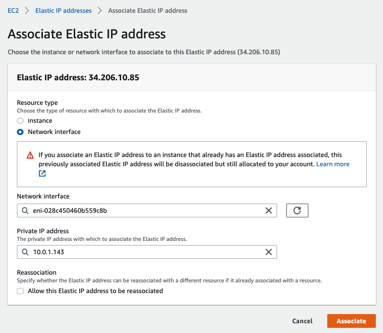
Access the PA via Elastic IP address.

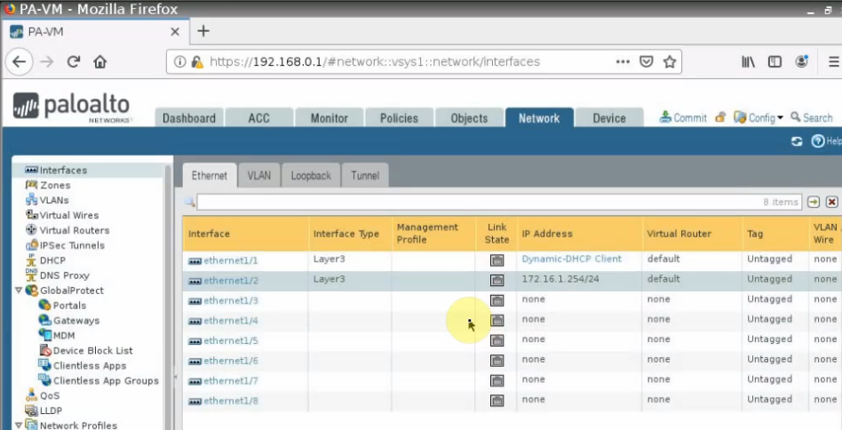
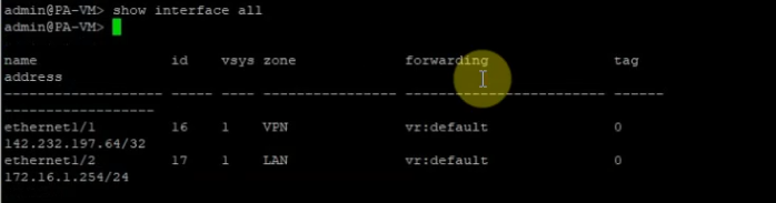
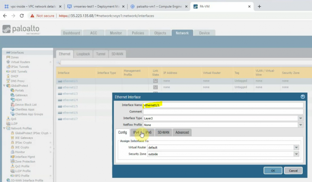
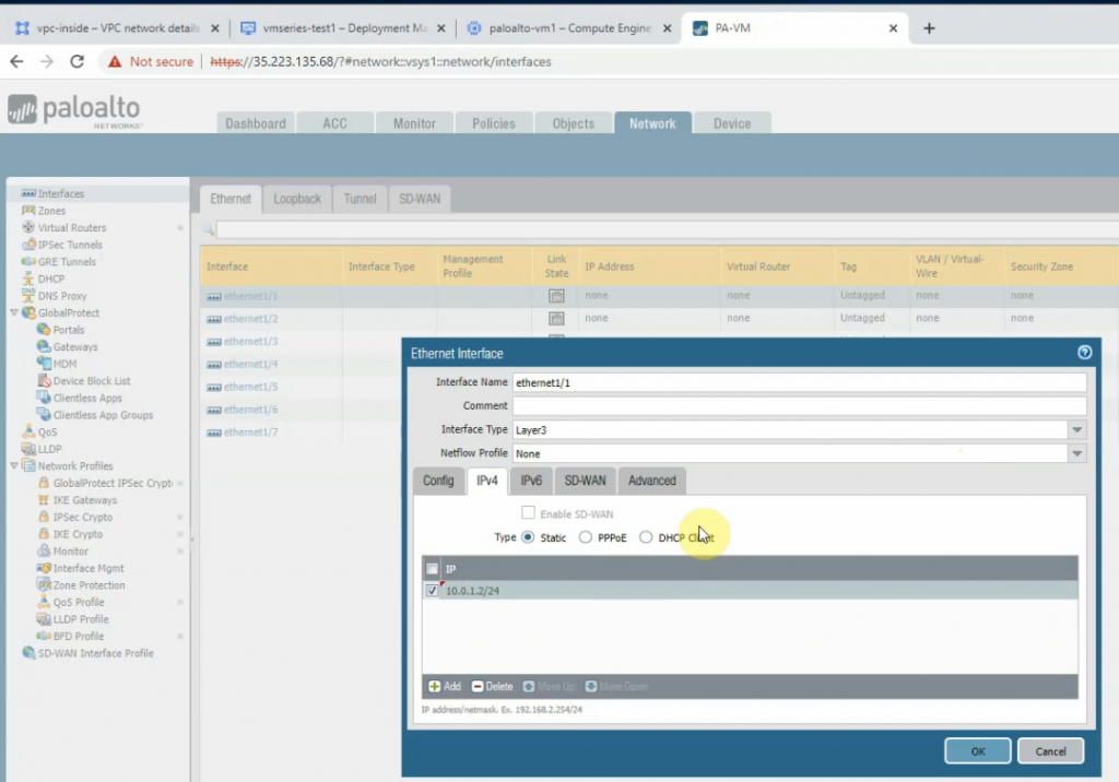
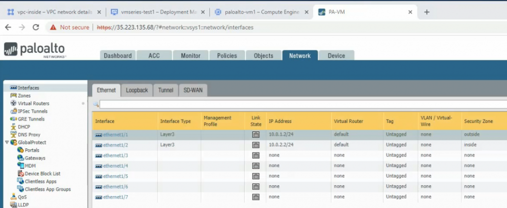
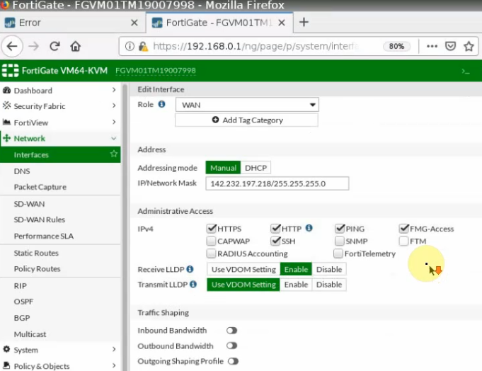
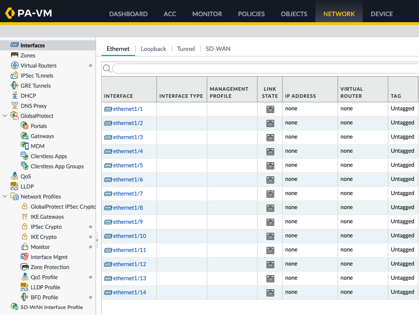
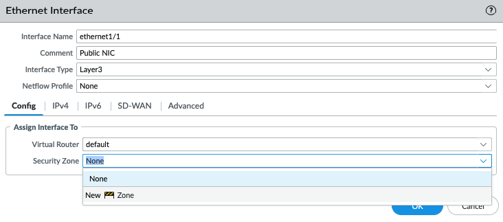
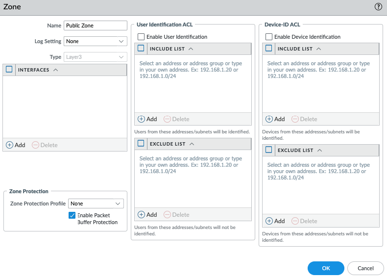
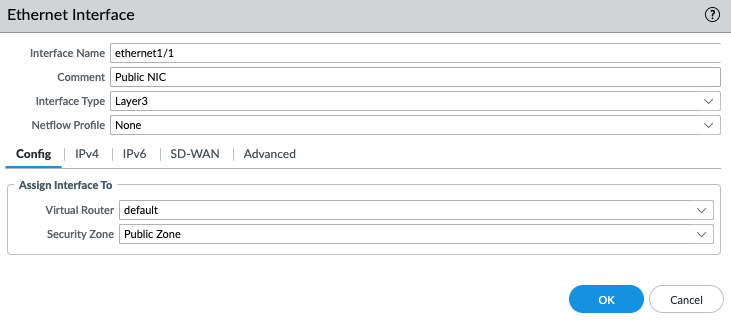
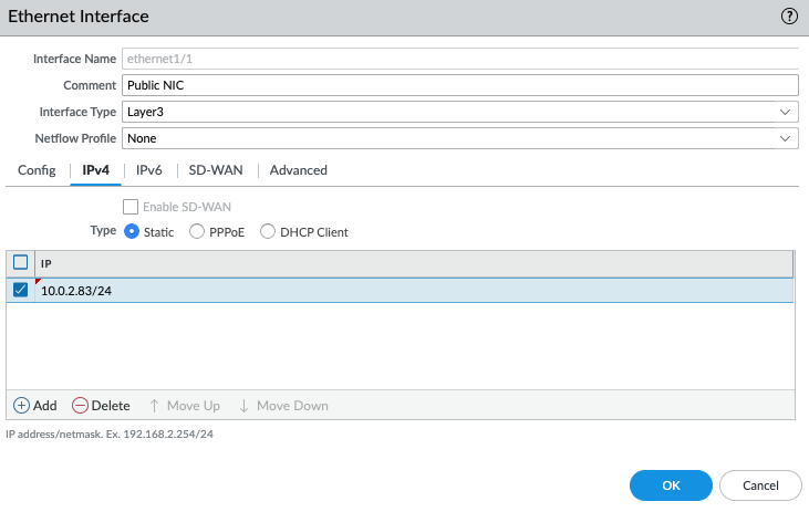
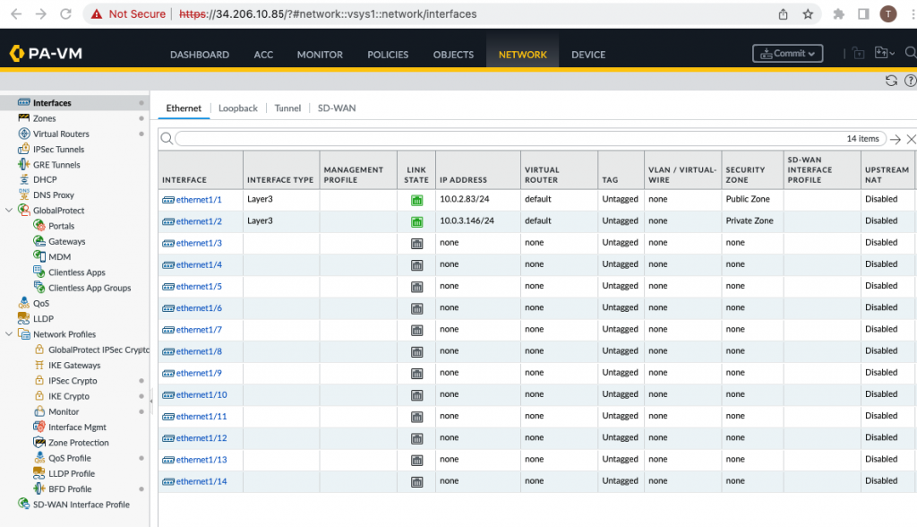
Configure the Public interface (e1/1) of PA.

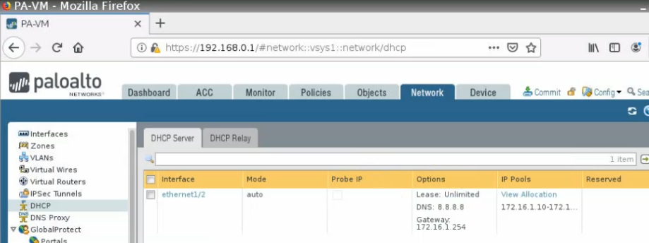
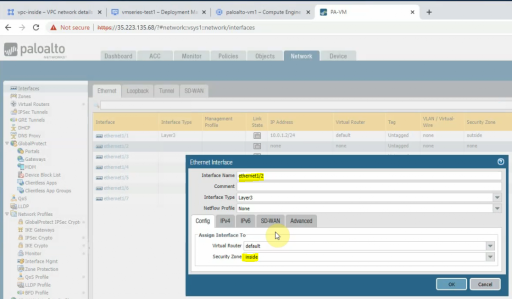
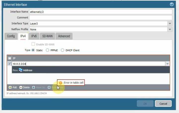
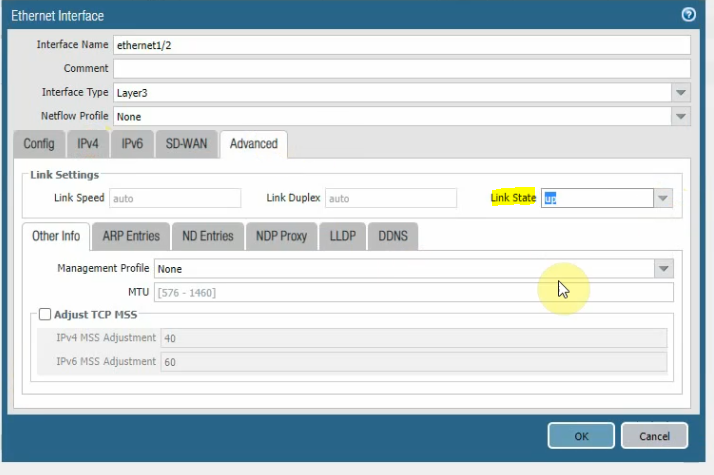
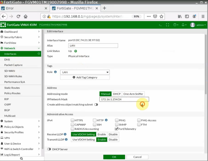
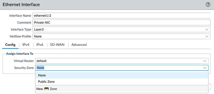
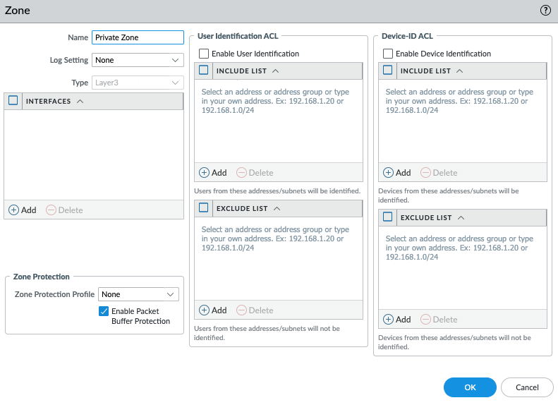
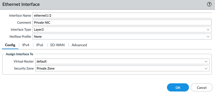
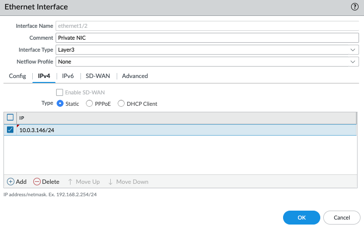
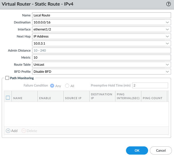
Configure the Private interface (e1/2) of PA.

Commit the settings.

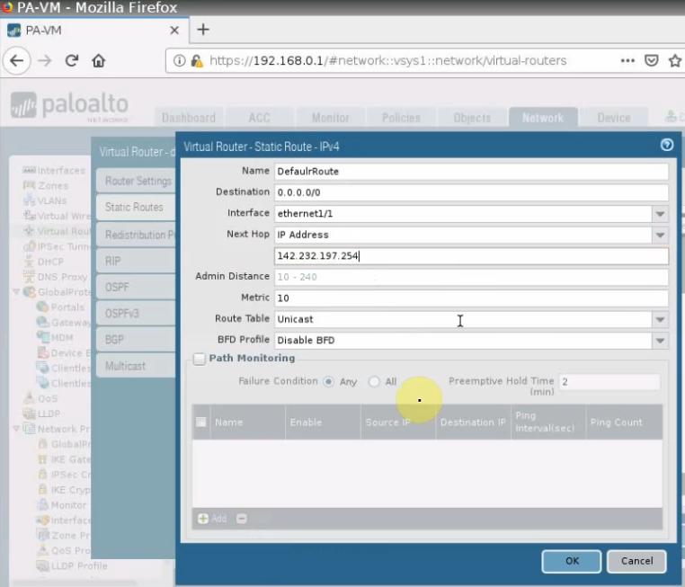
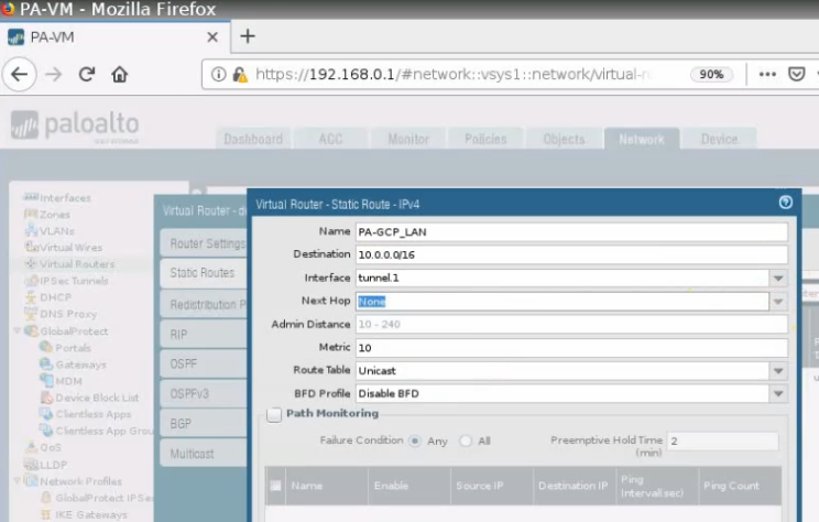
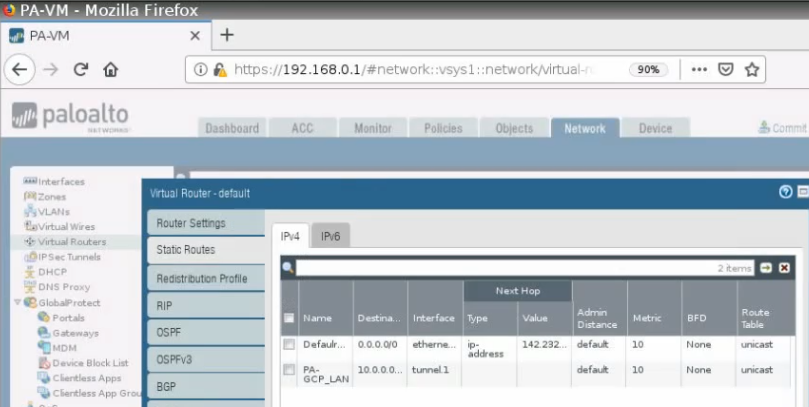
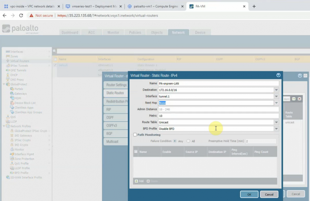
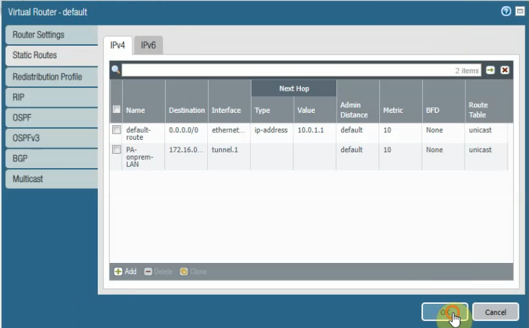
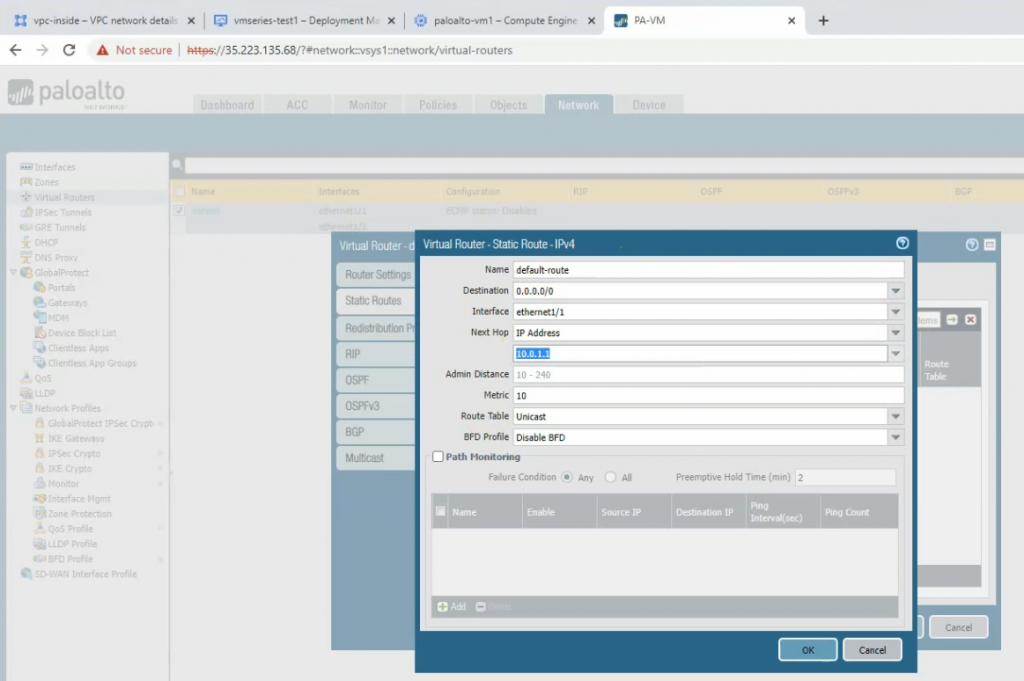
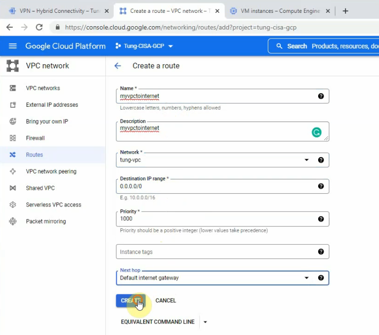
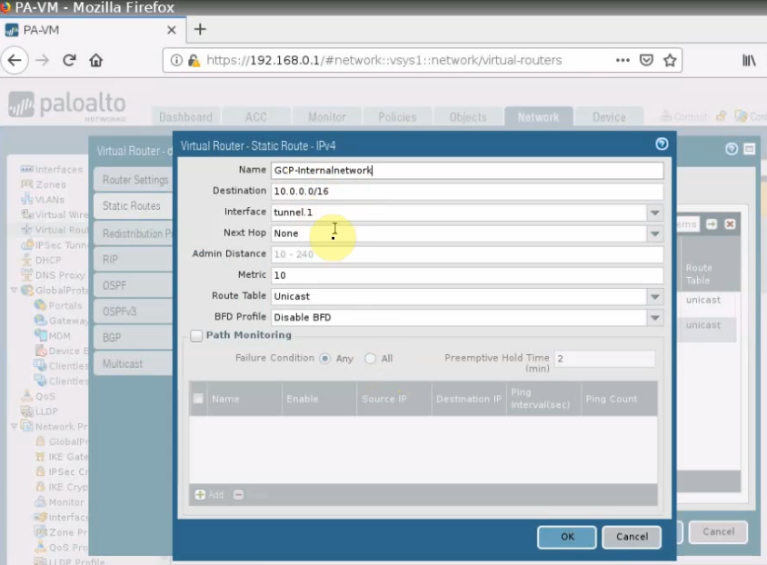
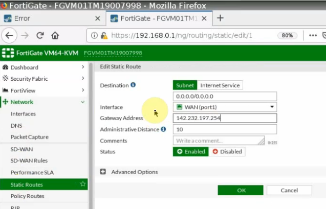
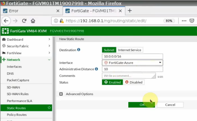
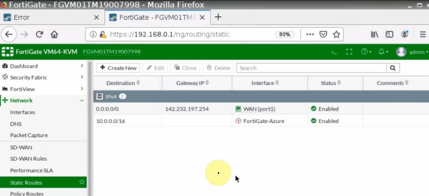
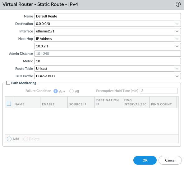
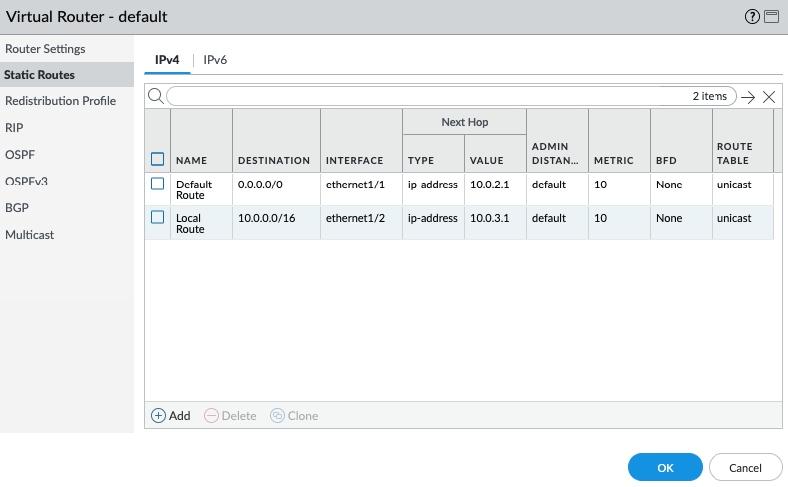
Create a default route via the Public interface.

Create a local route to allow traffic from the PVC network via the Private interface.

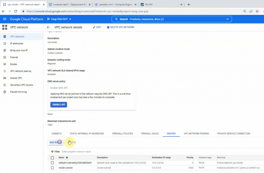
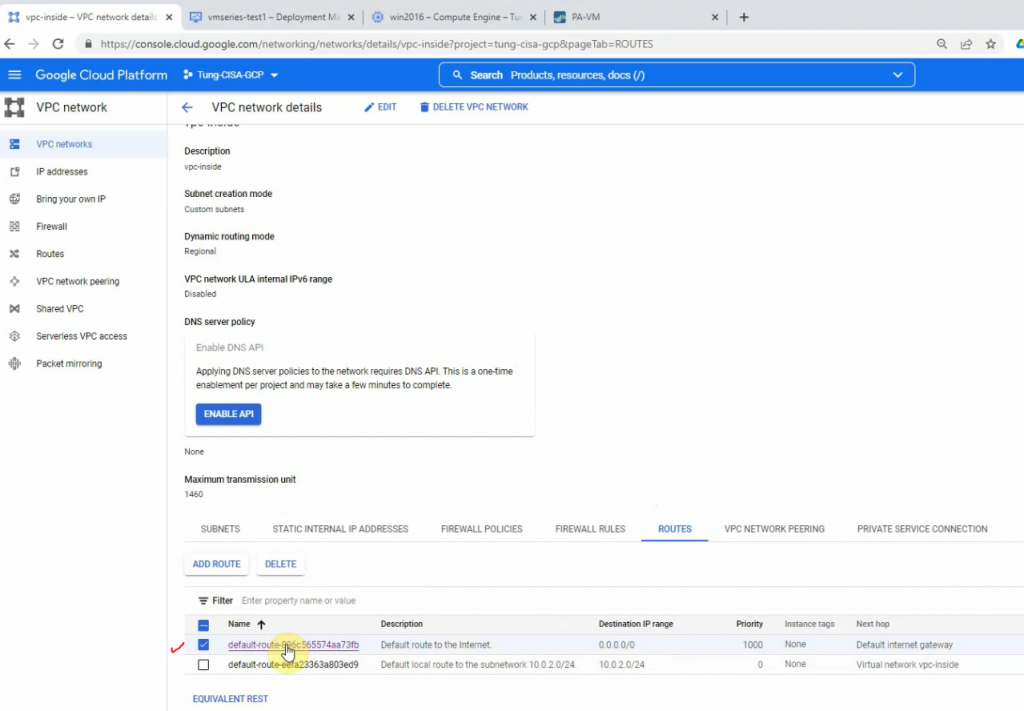
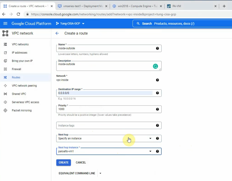
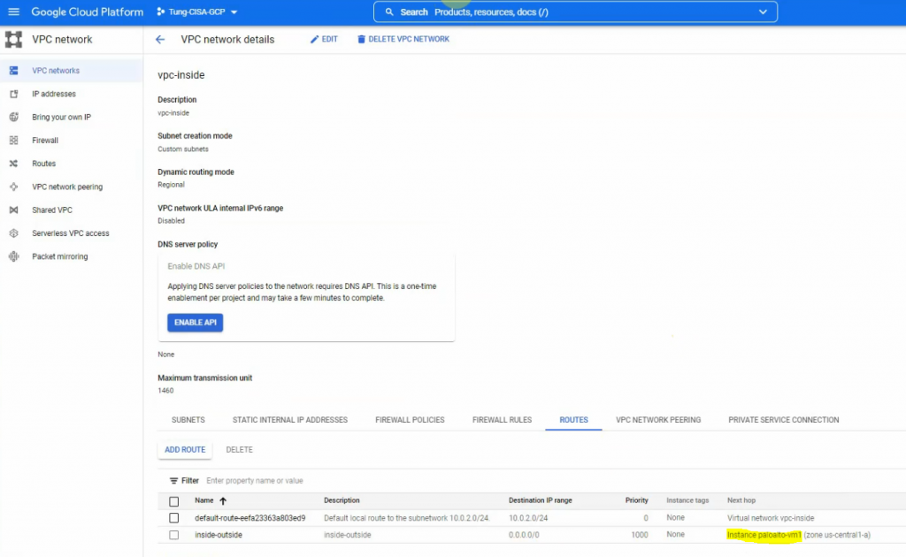
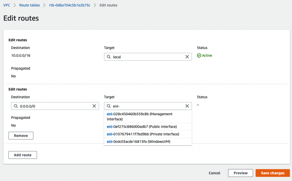
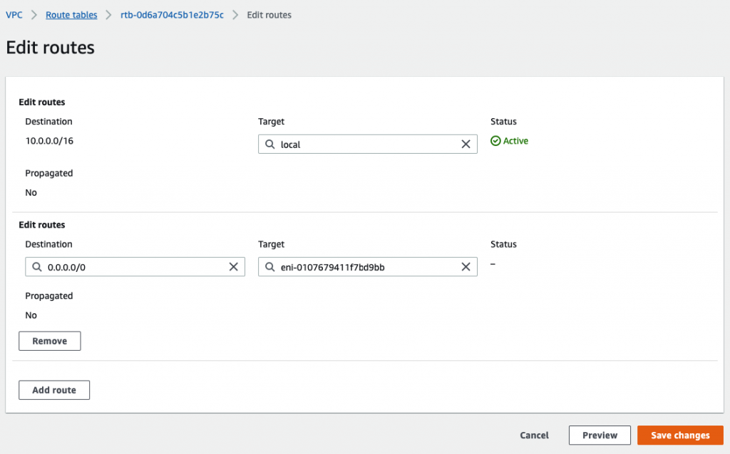
Back to VPC, edit routes in “Private route”.

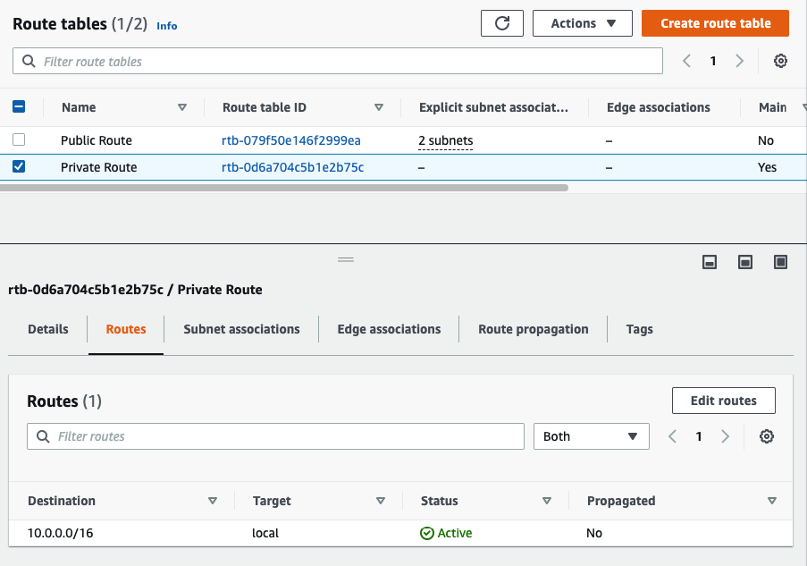
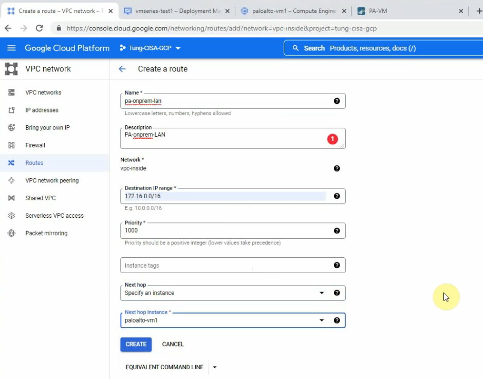
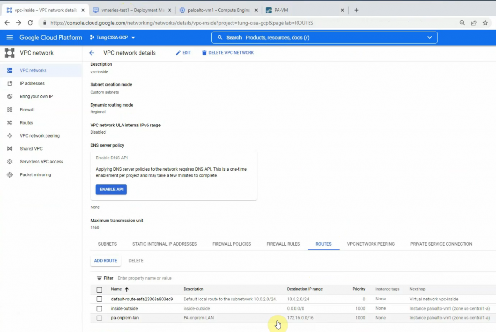
Add a default route via “Private network”.

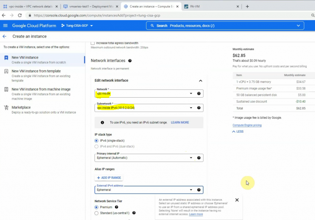
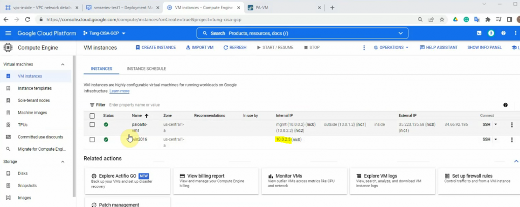
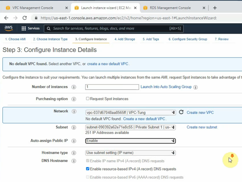
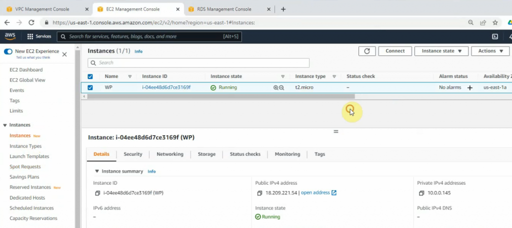
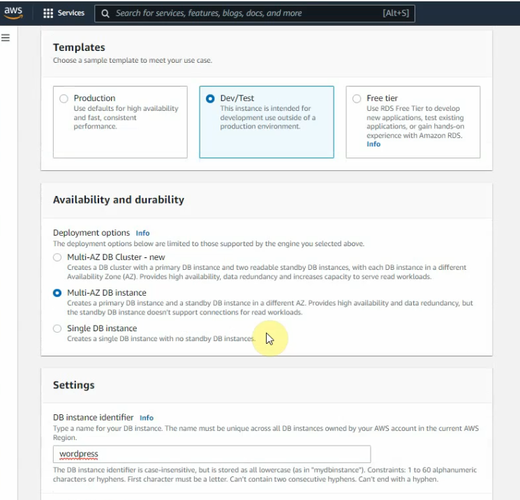
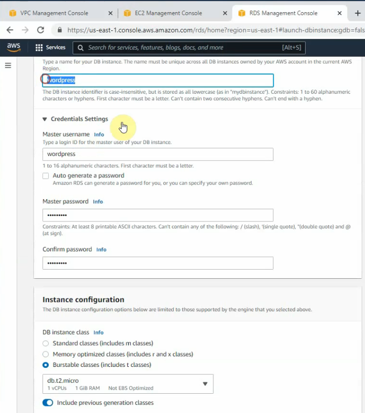
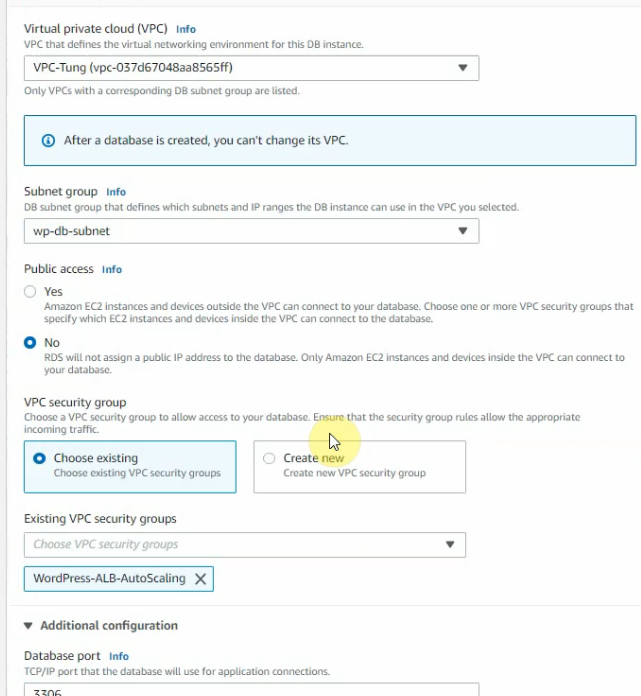
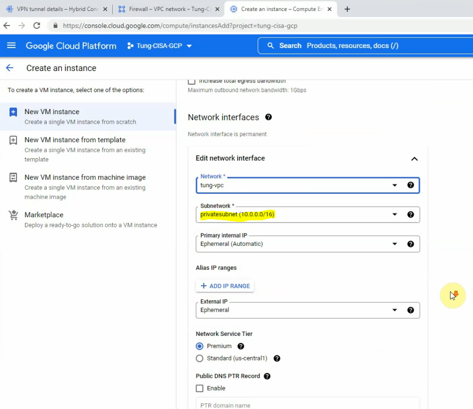
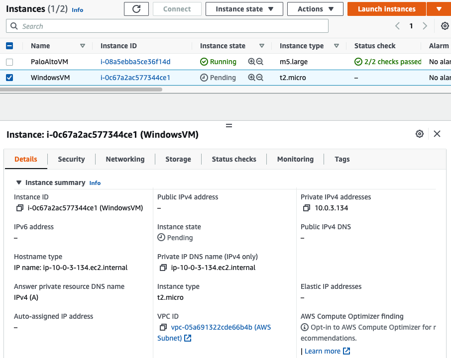
Back to EC2 – instances, create a new Windows VM in the Private network.

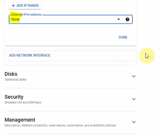
Select “Private Subnet” in Subnet setting and Disable in “Auto-assign Public IP”.

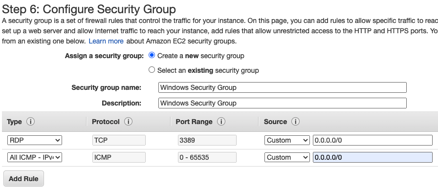
Add the ICMP line to allow ICMP traffic in this Security Group.

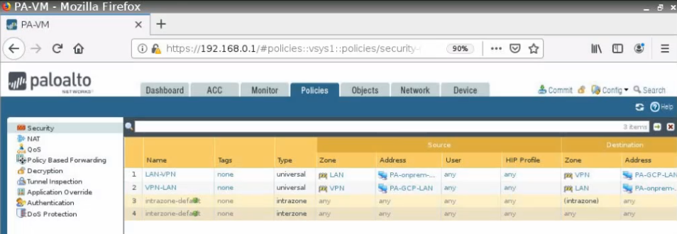
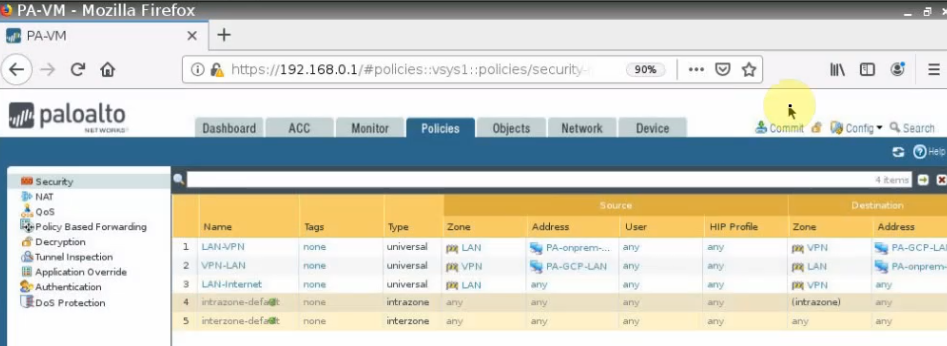
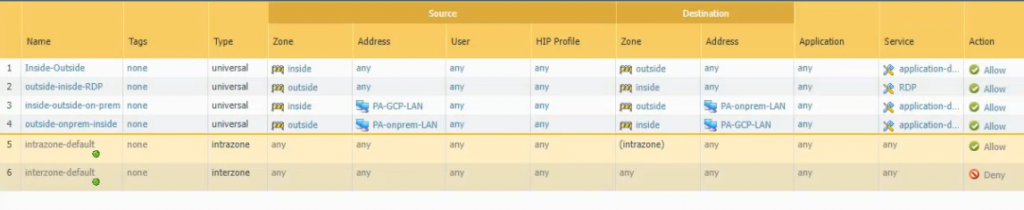
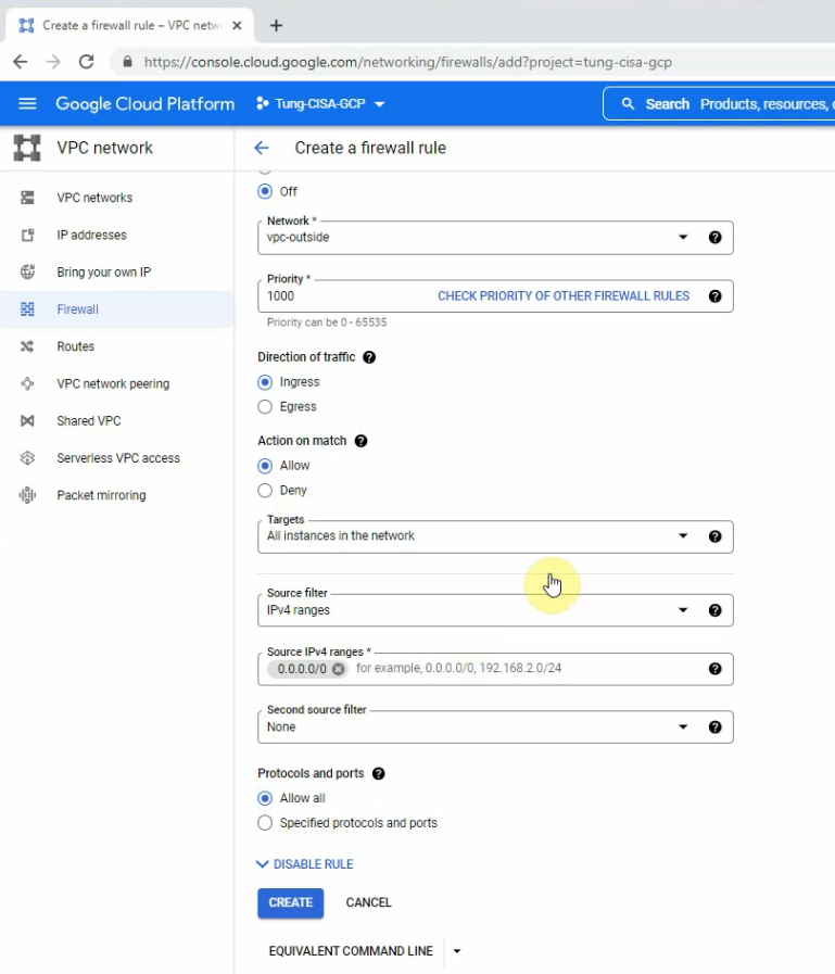
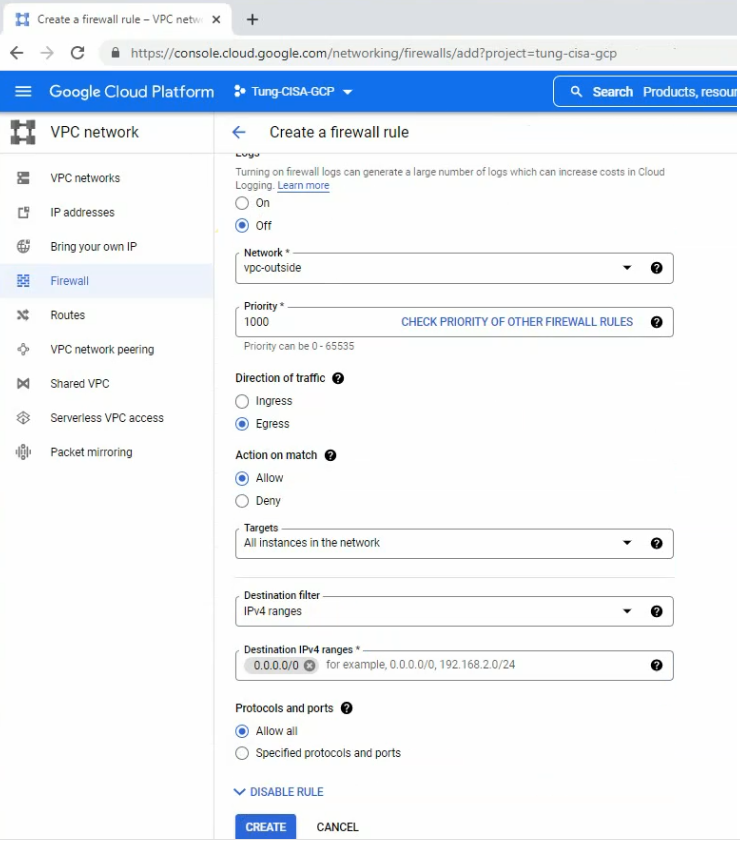
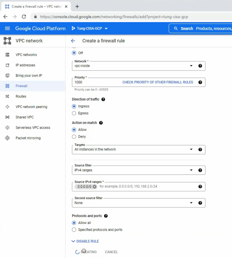
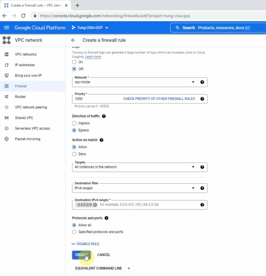
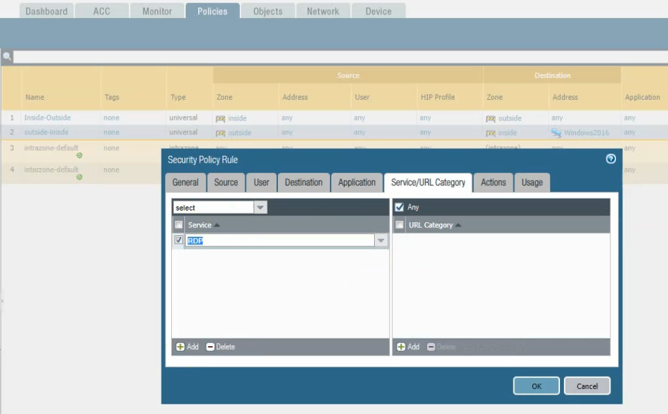
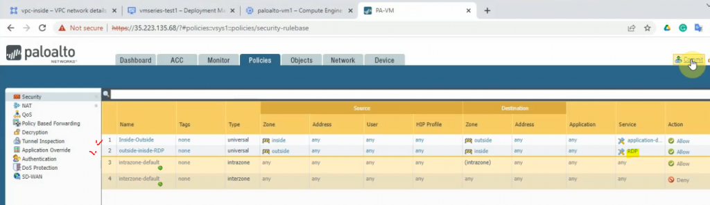
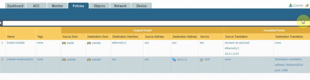
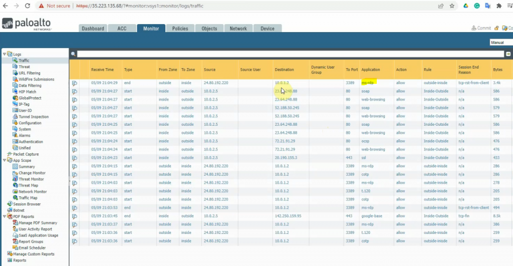
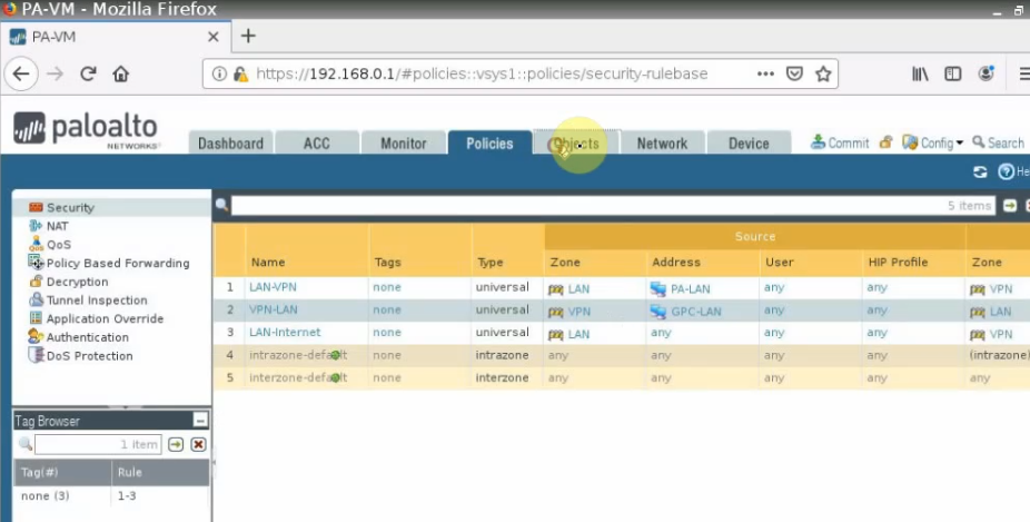
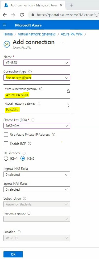
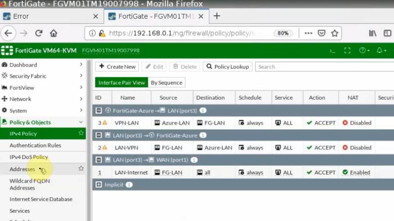
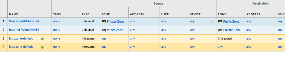
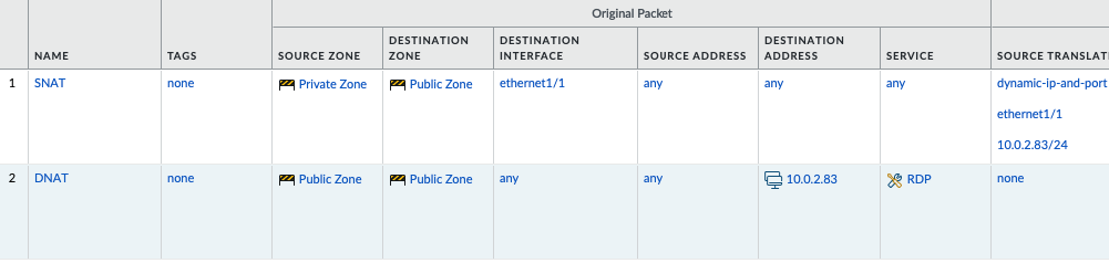
Move to PA, create 2 security polices to allow traffic from Private Zone to Public Zone and vice versa.

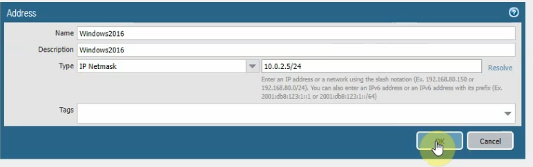
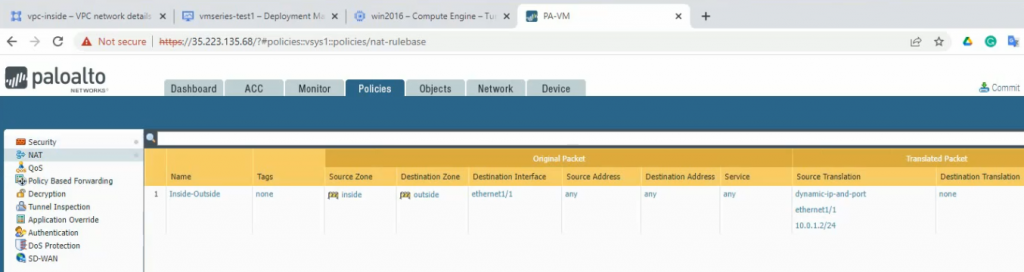
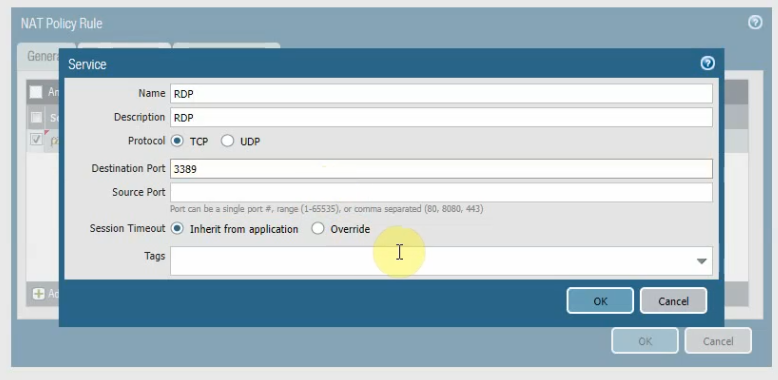
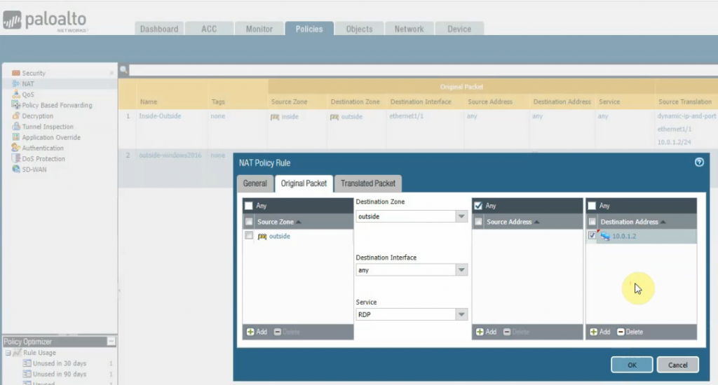
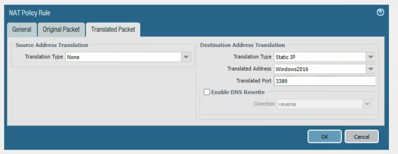
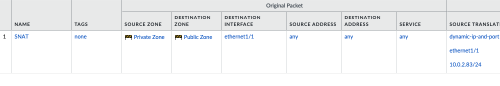
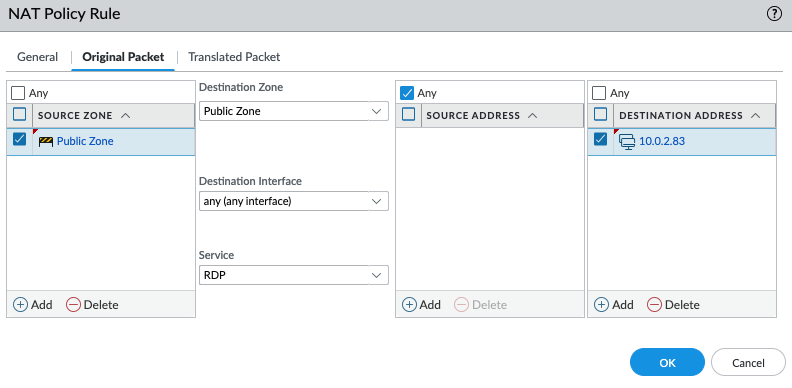
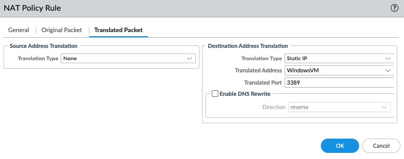
Create a SNAT and DNAT to allow traffic from Windows VM to the Internet and RDP traffic from Internet to Windows VM in Private subnet.

SNAT.

DNAT.

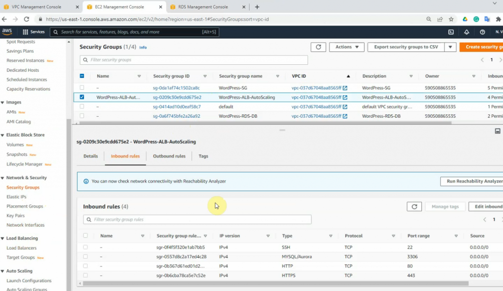
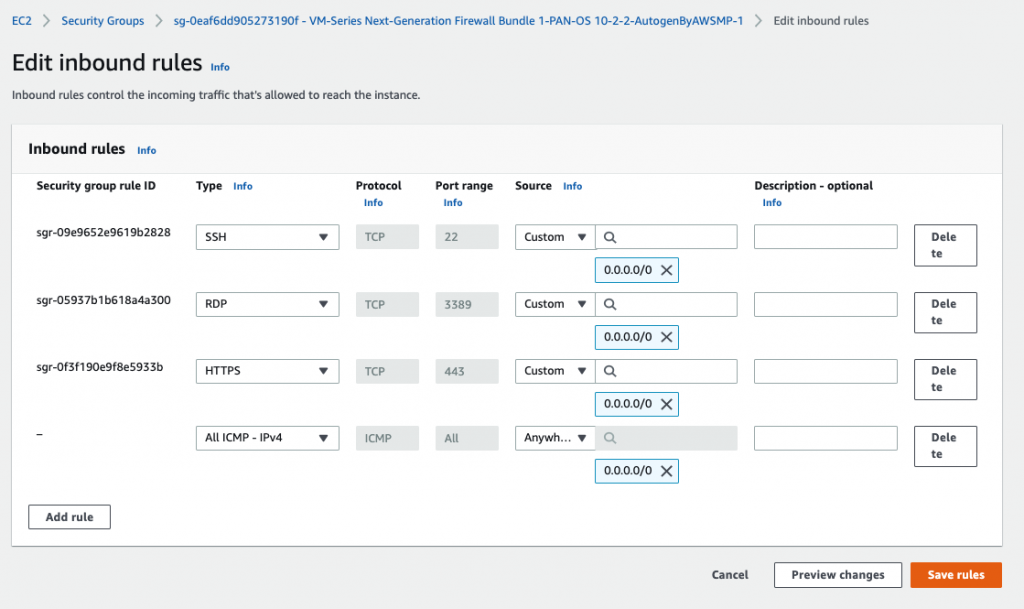
Back to AWS – EC2 – Security Group, add RDP and ICMP into the following Security Group.

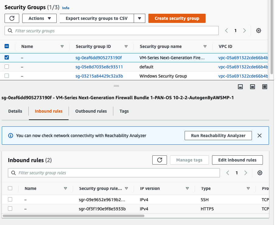
Add RDP and ICMP into this Security Group.

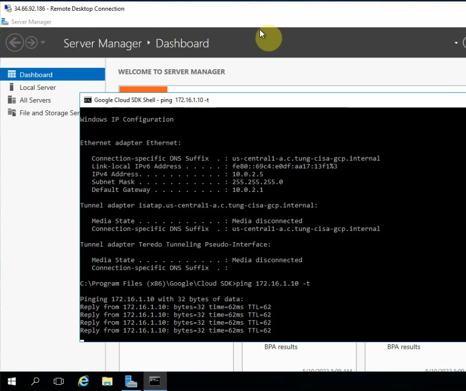
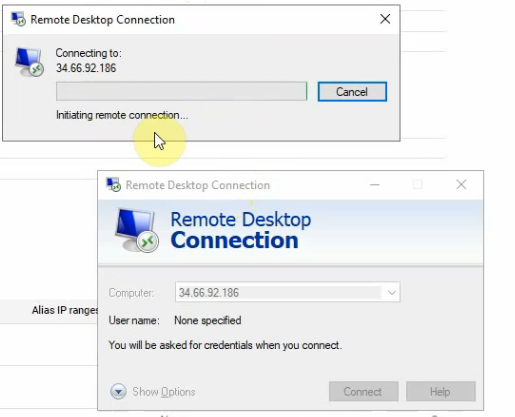
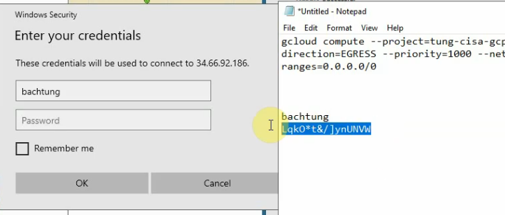
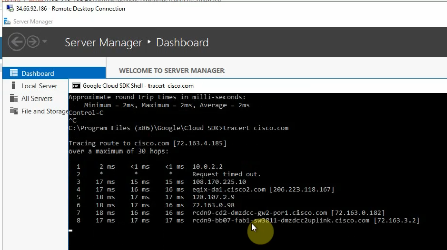
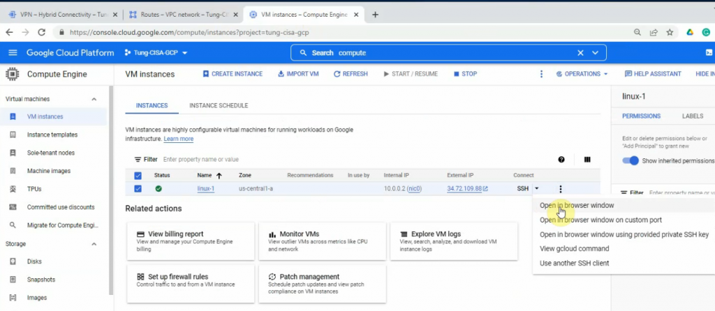
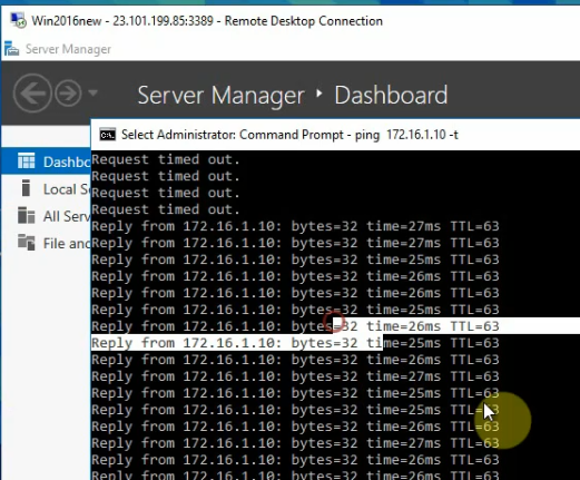
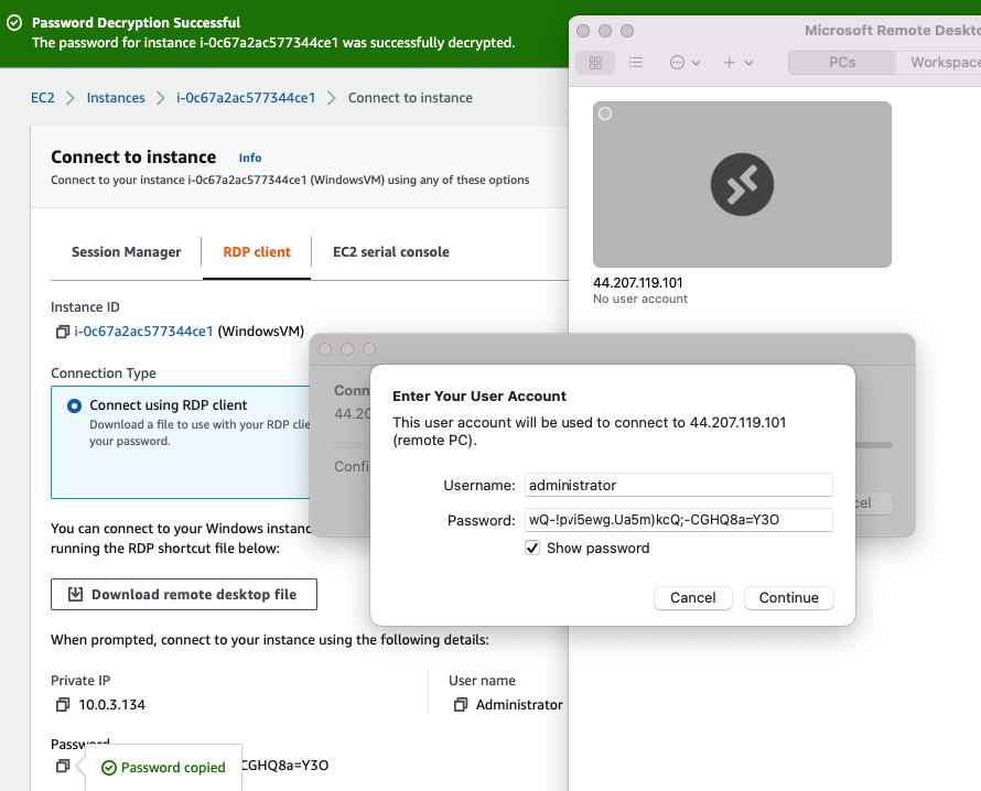
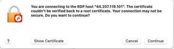
Now access RDP to Windows VM via Public EIP.

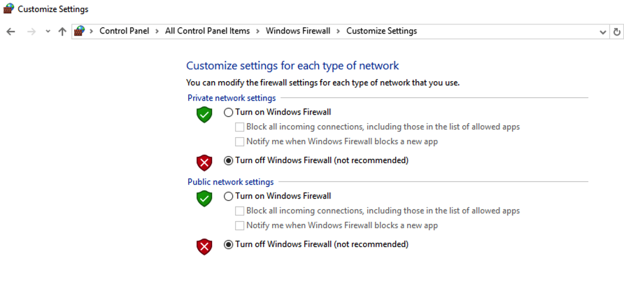
Disable Windows Firewall.

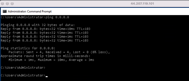
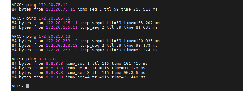
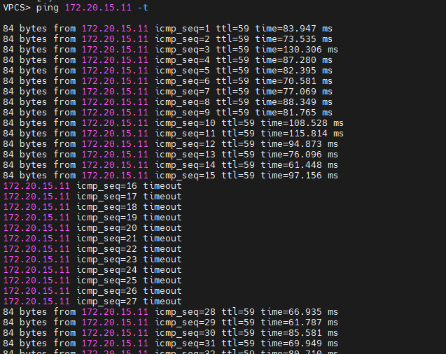
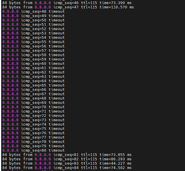
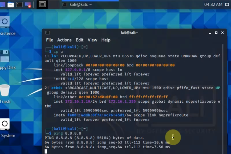
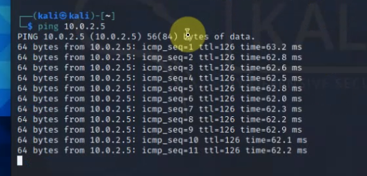
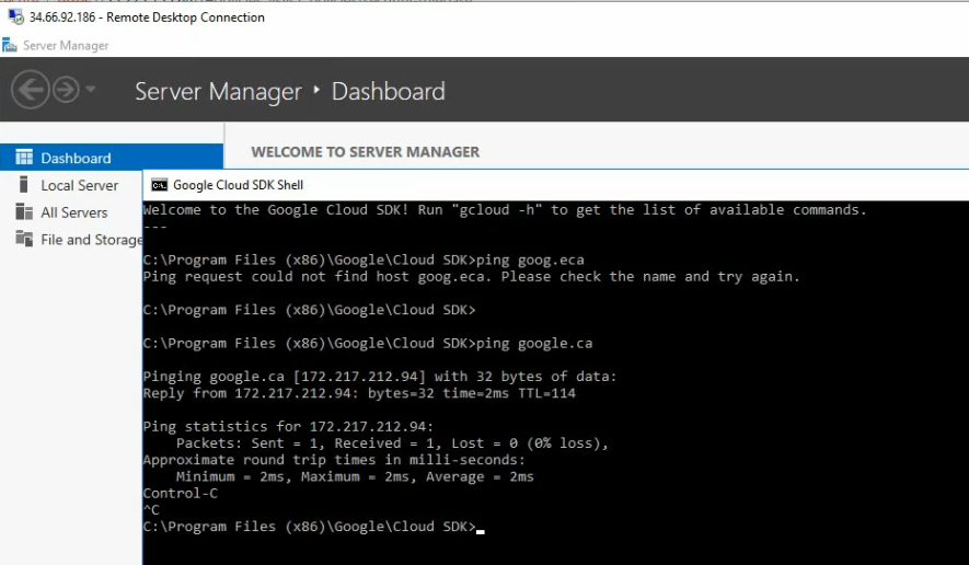
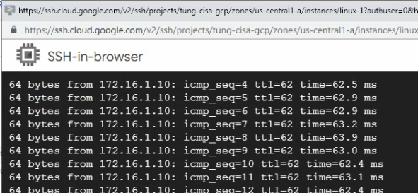
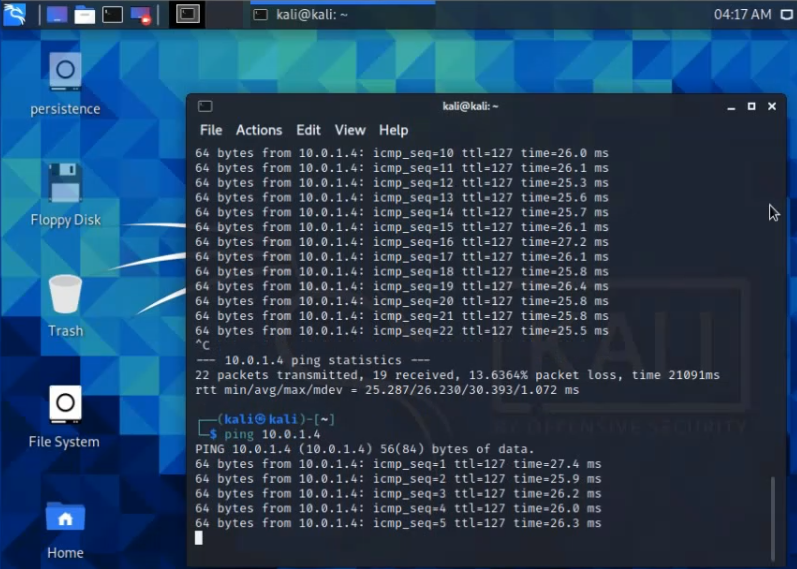
Ping 8.8.8.8 from Windows instance.

Enterprise Network Project

This is a diagram that I have used to implement the project.

This topology is used to set up for a small national service provider to provide connectivity for customers located in Vancouver, Toronto, and Calgary. The Service Provider has a location for shared services location to act as NOC by all clients. All sites have centralized Internet access via an MPLS-enabled core network in Vancouver head quarter. The design must meet the following requirements:

  • Connectivity, Security and traffic separation, Reliability
  • Access to the shared services
  • Secure Internet Access
  • Use Layer 2 technologies: VLANs/VTP/Trunks/Etherchannel/STP
  • User Layer 3 technologies: Dynamic routing/MP-BGP/NAT/VPNs/MPLS/VRF/6VPE/PE-CE routing/ Route redistribution/RADIUS/TACACS
PE1-R1Gig 1/0G1/0/1-P3D7-P210.40.71.1 
 Gig 0/0Gig 1/0/1-P3D6-P110.40.61.1 
 Gig 2/0 VLAN10G0/0-CE1-Vancouver172.20.63.2542001:172:20:63::254/64
 lo010.40.255.1  
PE2-R2Gig 1/0G1/0/2-P3D7-P210.40.72.2 
 Gig 0/0Gig 1/0/1-P3D6-P110.40.62.2 
 Gig 2/0G0/0-CE2-Toronto172.20.40.2542001:172:20:40::254/64
 lo010.40.255.2  
PE3-R3Gig 1/0G1/0/3-P3D7-P210.40.73.3 
 Gig 0/0Gig 1/0/3- P3D6-P110.40.63.3 
 Gig 2/0G0/0-CE3-Calgary172.20.127.2542001:172:20:127::254/64
 lo010.40.255.3  
PE4-R4Gig 1/0G1/0/4-P3D7-P210.40.74.4 
 Gig 0/0Gig 1/0/4- P3D6-P110.40.64.4 
 Gig 2/0G0/0-CE3-NOC172.20.254.2542001:172:20:254::254/64
 lo0 10.40.255.4  
PE5-R5Gig 0/0/0 Gig 0/1/1-P3D6-P110.40.65.5 
 Gig 0/0/1Gig0/1/1-P3D7-P210.40.75.5 
 vlan1VRF internetDHCP (10.0.0.x) 
 lo010.40.255.5  
P1-D6Gig 1/0/5Gig 0/0/0-B2R3-PE510.40.65.6 
 Gig 1/0/3Gig 0/0/0-P4R1-PE310.40.63.6 
 Gig 1/0/4Gig 0/0/0-P4R2-PE410.40.64.6 
 Gig 1/0/1Gig 0/0/0-P3R1-PE110.40.61.6 
 Gig 1/0/2Gig 0/0/0-P3R2-PE210.40.62.6 
 Gig 3/2-3Gig 3/2-3-P3D7-P210.40.67.6 Po1 
 Gig 1/0/23Gig 1/0/23-P3D7-P210.40.67.6 Po1
P2-D7Gig 1/0/5Gig 0/0/1-B2R3-PE510.40.75.7
 Gig 1/0/3Gig 0/0/1-P4R1-PE310.40.73.7
 Gig 1/0/4Gig 0/0/1-P4R2-PE410.40.74.7
 Gig 1/0/1Gig 0/0/1-P3R1-PE110.40.71.7
 Gig 1/0/2Gig 0/0/1-P3R2-PE210.40.72.7
 Gig 3/2Gig 3/2-P3D7-P210.40.67.7 Po1
 Gig 3/3Gig 3/3-P3D7-P210.40.67.7 Po1

On P1-D6:

hostname P1-D6-Tung
no ip domain lookup
ip domain name labs.bcit
vtp domain cisalab.local
vtp mode transparent
vlan 666
 name ParkingLot
interface Loopback0
 ip address 10.40.255.6 255.255.255.255
interface Port-channel1
 no switchport
 ip address 10.40.67.6 255.255.255.0
interface GigabitEthernet0/0
 no switchport
 ip address 10.40.61.6 255.255.255.0
!
interface GigabitEthernet0/1
 no switchport
 ip address 10.40.62.6 255.255.255.0
!
interface GigabitEthernet0/2
 no switchport
 ip address 10.40.63.6 255.255.255.0
!
interface GigabitEthernet0/3
 no switchport
 ip address 10.40.64.6 255.255.255.0
!
interface GigabitEthernet1/0
 no switchport
 ip address 10.40.65.6 255.255.255.0
!
vlan 666
 name Parkinglot
!
interface Loopback0
 ip address 10.40.255.7 255.255.255.255
!
interface Port-channel1
 no switchport
 ip address 10.40.67.7 255.255.255.0
!
interface GigabitEthernet0/0
 no switchport
 ip address 10.40.71.7 255.255.255.0
!
interface GigabitEthernet0/1
 no switchport
 ip address 10.40.72.7 255.255.255.0
!
interface GigabitEthernet0/2
 no switchport
 ip address 10.40.73.7 255.255.255.0
!
interface GigabitEthernet0/3
 no switchport
 ip address 10.40.74.7 255.255.255.0
!
interface GigabitEthernet1/0
 no switchport
 ip address 10.40.75.7 255.255.255.0
!

interface GigabitEthernet3/2
 no switchport
 no ip address
 channel-group 1 mode active
!
interface GigabitEthernet3/3
 no switchport
 no ip address
 channel-group 1 mode active
!
router ospf 40
 network 10.40.0.0 0.0.255.255 area 40
 mpls ldp sync
 mpls ldp autoconfig
## No autoconfig feature on D6
int range g0/0-3
mpls ip
int range g3/2-3
mpls ip
int g1/0
mpls ip

On P2-D7.

hostname P2D7-Tung

no ip domain lookup
ip domain name labs.bcit
vtp domain cisalab.local
vtp mode transparent
vlan 666
 name Parkinglot
!
interface Loopback0
 ip address 10.40.255.7 255.255.255.255
!
interface Port-channel1
 no switchport
 ip address 10.40.67.7 255.255.255.0
!
interface GigabitEthernet0/0
 no switchport
 ip address 10.40.71.7 255.255.255.0
!
interface GigabitEthernet0/1
 no switchport
 ip address 10.40.72.7 255.255.255.0
!
interface GigabitEthernet0/2
 no switchport
 ip address 10.40.73.7 255.255.255.0
!
interface GigabitEthernet0/3
 no switchport
 ip address 10.40.74.7 255.255.255.0
!
interface GigabitEthernet1/0
 no switchport
 ip address 10.40.75.7 255.255.255.0
!

interface GigabitEthernet3/2
 no switchport
 no ip address
 channel-group 1 mode active
!
interface GigabitEthernet3/3
 no switchport
 no ip address
 channel-group 1 mode active
router ospf 40
 network 10.40.0.0 0.0.255.255 area 40
 mpls ldp sync
 mpls ldp autoconfig

## No autoconfig on D7
int range g0/0-3
mpls ip
int range g3/2-3
mpls ip
int g1/0
mpls ip

On PE1-Tung

hostname hostname P3R1-PE1
## Create a vrf Cust1 and define a rd, export and imporrt route-target 
vrf definition Cust1
 rd 1:1
 route-target export 1:20
 route-target import 1:20
 route-target import 1:100
 !
 address-family ipv4
 exit-address-family
 !
 address-family ipv6
 exit-address-family
no ip domain lookup
ip domain name labs.bcit
!
ipv6 unicast-routing
interface Loopback0
 ip address 10.40.255.1 255.255.255.255
!
interface GigabitEthernet0/0
 description to P1
 ip address 10.40.61.1 255.255.255.0
 negotiation auto
!
interface GigabitEthernet1/0
 description to P2
 ip address 10.40.71.1 255.255.255.0
 negotiation auto
!
interface GigabitEthernet2/0
 vrf forwarding Cust1
 ip address 172.20.63.254 255.255.255.0
 ipv6 address 2001:172:20:63::254/64
 no shut
!
# Enable EIGRP named mode and redistribute bgp to EIGRP
router eigrp TungLe
 !
 address-family ipv4 unicast vrf Cust1 autonomous-system 20
  !
  topology base
   default-metric 2000 100 255 1 1500
   redistribute bgp 40
  exit-af-topology
  network 172.20.0.0
 exit-address-family
 !
 address-family ipv6 unicast vrf Cust1 autonomous-system 20
  !
  topology base
   default-metric 2000 100 255 1 1500
   redistribute bgp 40
  exit-af-topology
 exit-address-family
!
# Enable OSPF and MPLS enabled-core
router ospf 40
 network 10.40.0.0 0.0.255.255 area 40
 mpls ldp sync
 mpls ldp autoconfig
# Enable MP-BGP with AS 40, activate vpnv4 and vpnv6 to support IPv4 and Ipv6 via BGP network
router bgp 40
 bgp log-neighbor-changes
 neighbor STA40 peer-group
 neighbor STA40 remote-as 40
 neighbor STA40 update-source Loopback0
 neighbor 10.40.255.2 peer-group STA40
 neighbor 10.40.255.3 peer-group STA40
 neighbor 10.40.255.4 peer-group STA40
 neighbor 10.40.255.5 peer-group STA40
 !
 address-family ipv4
  neighbor 10.40.255.2 activate
  neighbor 10.40.255.3 activate
  neighbor 10.40.255.4 activate
  neighbor 10.40.255.5 activate
 exit-address-family
 !
 address-family vpnv4
  neighbor STA40 send-community extended
  neighbor 10.40.255.2 activate
  neighbor 10.40.255.3 activate
  neighbor 10.40.255.4 activate
  neighbor 10.40.255.5 activate
 exit-address-family
 !
 address-family vpnv6
  neighbor STA40 send-community extended
  neighbor 10.40.255.2 activate
  neighbor 10.40.255.3 activate
  neighbor 10.40.255.4 activate
  neighbor 10.40.255.5 activate
 exit-address-family
 !

# Activate BGP on vrf Cust1 for IPv4 and Ipv6. Redistribute EIGRP IPv4/IPV6 named mode to BGP 
 address-family ipv4 vrf Cust1
  redistribute eigrp 20
 exit-address-family
 !
 address-family ipv6 vrf Cust1
  redistribute eigrp 20 include-connected
 exit-address-family
 !

On PE2-Tung

hostname P3R2-PE2-Tung
vrf definition Cust1
 rd 1:2
 route-target export 1:20
 route-target import 1:20
 route-target import 1:100
 !
 address-family ipv4
 exit-address-family
 !
 address-family ipv6
 exit-address-family
!
no ip domain lookup
ip domain name labs.bcit
!
ipv6 unicast-routing
interface Loopback0
 ip address 10.40.255.2 255.255.255.255
!
interface GigabitEthernet0/0
 description to P1
 ip address 10.40.62.2 255.255.255.0
 negotiation auto
!
interface GigabitEthernet1/0
 description to P2
 ip address 10.40.72.2 255.255.255.0
 negotiation auto
!
interface GigabitEthernet2/0
 vrf forwarding Cust1
 ip address 172.20.95.254 255.255.255.0
 ipv6 address 2001:172:20:95::254/64
 no shut
!
router eigrp TungLe
 !
 address-family ipv4 unicast vrf Cust1 autonomous-system 20
  !
  topology base
   default-metric 2000 100 255 1 1500
   redistribute bgp 40
  exit-af-topology
  network 172.20.0.0
 exit-address-family
 !
 address-family ipv6 unicast vrf Cust1 autonomous-system 20
  !
  topology base
   default-metric 2000 100 255 1 1500
   redistribute bgp 40
  exit-af-topology
 exit-address-family
!
router ospf 40
 network 10.40.0.0 0.0.255.255 area 40
 mpls ldp sync
 mpls ldp autoconfig
!
router bgp 40
 bgp log-neighbor-changes
 neighbor STA40 peer-group
 neighbor STA40 remote-as 40
 neighbor STA40 update-source Loopback0
 neighbor 10.40.255.1 peer-group STA40
 neighbor 10.40.255.3 peer-group STA40
 neighbor 10.40.255.4 peer-group STA40
 neighbor 10.40.255.5 peer-group STA40
 !
 address-family ipv4
  neighbor 10.40.255.1 activate
  neighbor 10.40.255.3 activate
  neighbor 10.40.255.4 activate
  neighbor 10.40.255.5 activate
 exit-address-family
 !
 address-family vpnv4
  neighbor STA40 send-community extended
  neighbor 10.40.255.1 activate
  neighbor 10.40.255.3 activate
  neighbor 10.40.255.4 activate
  neighbor 10.40.255.5 activate
 exit-address-family
 !
 address-family vpnv6
  neighbor STA40 send-community extended
  neighbor 10.40.255.1 activate
  neighbor 10.40.255.3 activate
  neighbor 10.40.255.4 activate
  neighbor 10.40.255.5 activate
 exit-address-family
 !
 address-family ipv4 vrf Cust1
  redistribute eigrp 20
 exit-address-family
 !
 address-family ipv6 vrf Cust1
  redistribute eigrp 20 include-connected
 exit-address-family
 !

+ On PE3-Tung

hostname P4R1-PE3-Tung
!
vrf definition Cust1
 rd 1:3
 route-target export 1:20
 route-target import 1:20
 route-target import 1:100
 !
 address-family ipv4
 exit-address-family
 !
 address-family ipv6
 exit-address-family
no ip domain lookup
ip domain name labs.bcit
!
ipv6 unicast-routing
interface Loopback0
 ip address 10.40.255.3 255.255.255.255
!
interface GigabitEthernet0/0
 description to P1
 ip address 10.40.63.3 255.255.255.0
 negotiation auto
!
interface GigabitEthernet1/0
 description to P2
 ip address 10.40.73.3 255.255.255.0
 negotiation auto
!
interface GigabitEthernet2/0
 vrf forwarding Cust1
 ip address 172.20.127.254 255.255.255.0
 ipv6 address 2001:172:20:127::254/64
 no shut
!
router eigrp TungLe
 !
 address-family ipv4 unicast vrf Cust1 autonomous-system 20
  !
  topology base
   default-metric 2000 100 255 1 1500
   redistribute bgp 40
  exit-af-topology
  network 172.20.0.0
 exit-address-family
 !
 address-family ipv6 unicast vrf Cust1 autonomous-system 20
  !
  topology base
   default-metric 2000 100 255 1 1500
   redistribute bgp 40
  exit-af-topology
 exit-address-family
 !
 address-family ipv4 unicast vrf kirk autonomous-system 100
  !
  topology base
   default-metric 1000 100 1 255 1500
   redistribute bgp 40
  exit-af-topology
  network 172.19.0.0
 exit-address-family
 !
 address-family ipv6 unicast vrf kirk autonomous-system 100
  !
  topology base
   redistribute bgp 40
  exit-af-topology
 exit-address-family
!
router ospf 40
 network 10.40.0.0 0.0.255.255 area 40
 mpls ldp sync
 mpls ldp autoconfig
!
router bgp 40
 bgp log-neighbor-changes
 neighbor STA40 peer-group
 neighbor STA40 remote-as 40
 neighbor STA40 update-source Loopback0
 neighbor 10.40.255.1 peer-group STA40
 neighbor 10.40.255.2 peer-group STA40
 neighbor 10.40.255.4 peer-group STA40
 neighbor 10.40.255.5 peer-group STA40
 !
 address-family ipv4
  neighbor 10.40.255.1 activate
  neighbor 10.40.255.2 activate
  neighbor 10.40.255.4 activate
  neighbor 10.40.255.5 activate
 exit-address-family
 !
 address-family vpnv4
  neighbor STA40 send-community extended
  neighbor 10.40.255.1 activate
  neighbor 10.40.255.2 activate
  neighbor 10.40.255.4 activate
  neighbor 10.40.255.5 activate
 exit-address-family
 !
 address-family vpnv6
  neighbor STA40 send-community extended
  neighbor 10.40.255.1 activate
  neighbor 10.40.255.2 activate
  neighbor 10.40.255.4 activate
  neighbor 10.40.255.5 activate
 exit-address-family
 !
 address-family ipv4 vrf Cust1
  redistribute eigrp 20
 exit-address-family
 !
 address-family ipv6 vrf Cust1
  redistribute eigrp 20 include-connected
 exit-address-family
 !

+ on PE4-NOC

hostname P4R2-PE4-NOC
!
vrf definition Cust1
 rd 1:4
 route-target export 1:20
 route-target import 1:20
 route-target import 1:100
 !
 address-family ipv4
 exit-address-family
 !
 address-family ipv6
 exit-address-family
!
no ip domain lookup
ip domain name labs.bcit
ipv6 unicast-routing
interface Loopback0
 ip address 10.40.255.4 255.255.255.255
!
interface GigabitEthernet0/0
 description to P1
 ip address 10.40.64.4 255.255.255.0
 negotiation auto
!
interface GigabitEthernet1/0
 description to P2
 ip address 10.40.74.4 255.255.255.0
 negotiation auto
!
interface GigabitEthernet2/0
 vrf forwarding Cust1
 ip address 172.20.254.254 255.255.255.0
 ipv6 address 2001:172:20:254::254/64
 no shut
!
router eigrp TungLe
 !
 address-family ipv4 unicast vrf Cust1 autonomous-system 20
  !
  topology base
   default-metric 2000 100 255 1 1500
   redistribute bgp 40
  exit-af-topology
  network 172.20.0.0
 exit-address-family
 !
 address-family ipv6 unicast vrf Cust1 autonomous-system 20
  !
  topology base
   default-metric 2000 100 255 1 1500
   redistribute bgp 40
  exit-af-topology
 exit-address-family
 !
router ospf 40
 network 10.40.0.0 0.0.255.255 area 40
 mpls ldp sync
 mpls ldp autoconfig
!
router bgp 40
 bgp log-neighbor-changes
 neighbor STA40 peer-group
 neighbor STA40 remote-as 40
 neighbor STA40 update-source Loopback0
 neighbor 10.40.255.1 peer-group STA40
 neighbor 10.40.255.2 peer-group STA40
 neighbor 10.40.255.3 peer-group STA40
 neighbor 10.40.255.5 peer-group STA40
 !
 address-family ipv4
  neighbor 10.40.255.1 activate
  neighbor 10.40.255.2 activate
  neighbor 10.40.255.3 activate
  neighbor 10.40.255.5 activate
 exit-address-family
 !
 address-family vpnv4
  neighbor STA40 send-community extended
  neighbor 10.40.255.1 activate
  neighbor 10.40.255.2 activate
  neighbor 10.40.255.3 activate
  neighbor 10.40.255.5 activate
 exit-address-family
 !
 address-family vpnv6
  neighbor STA40 send-community extended
  neighbor 10.40.255.1 activate
  neighbor 10.40.255.2 activate 
  neighbor 10.40.255.3 activate
  neighbor 10.40.255.5 activate
 exit-address-family
 !
 address-family ipv4 vrf Cust1
  redistribute eigrp 20
 exit-address-family
 !
 address-family ipv6 vrf Cust1
  redistribute eigrp 20 include-connected
 exit-address-family
 !

+ On PE5-Tung

hostname B2R5-PE5-Tung
!

# Define vrf Internet and export route-target 1:100. Then we will import route-target 1:100 to all PE1, PE2, PE3, PE4. Import route-target 1:20 for PE1, PE2, PE3, PE4
vrf definition Internet
 rd 1:100
 route-target export 1:100
 route-target import 1:100
 route-target import 1:20
 !
 address-family ipv4
 exit-address-family
no ip domain lookup
ip domain name labs.bcit
!
ipv6 unicast-routing
interface Loopback0
 ip address 10.40.255.5 255.255.255.255
!
interface GigabitEthernet0/0
 description to P1
 ip address 10.40.65.5 255.255.255.0
 ip nat inside
 no shut
!
interface GigabitEthernet1/0
 description to P2
 ip address 10.40.75.5 255.255.255.0
 ip nat inside
 no shut
!
interface GigabitEthernet2/0
 description to Internet
 vrf forwarding Internet
 ip address dhcp
 ip nat outside
 no shut
!
router ospf 40
 network 10.40.0.0 0.0.255.255 area 40
 mpls ldp sync
 mpls ldp autoconfig
!
router bgp 40
 bgp log-neighbor-changes
 neighbor STA40 peer-group
 neighbor STA40 remote-as 40
 neighbor STA40 update-source Loopback0
 neighbor 10.40.255.1 peer-group STA40
 neighbor 10.40.255.2 peer-group STA40
 neighbor 10.40.255.3 peer-group STA40
 neighbor 10.40.255.4 peer-group STA40
 !
 address-family ipv4
  neighbor 10.40.255.1 activate
  neighbor 10.40.255.1 default-originate
  neighbor 10.40.255.2 activate
  neighbor 10.40.255.3 activate
  neighbor 10.40.255.4 activate
 exit-address-family
 !
 address-family vpnv4
  neighbor STA40 send-community extended
  neighbor 10.40.255.1 activate
  neighbor 10.40.255.2 activate
  neighbor 10.40.255.3 activate
  neighbor 10.40.255.4 activate
 exit-address-family
 !
 address-family vpnv6
  neighbor STA40 send-community extended
  neighbor 10.40.255.1 activate
  neighbor 10.40.255.2 activate
  neighbor 10.40.255.3 activate
  neighbor 10.40.255.4 activate
 exit-address-family
 !

# Distribute default static route via BGP to vrf Internet
 address-family ipv4 vrf Internet
  network 0.0.0.0
 exit-address-family
!

# Enable ip nat inside for vrf Internet via interface g2/0
ip nat inside source list 1 interface g2/0 vrf Internet overload
# Create a static default route for vrf Internet via 10.0.0.1 (simuate public network)
ip route vrf Internet 0.0.0.0 0.0.0.0 10.0.0.1
!
access-list 1 permit 172.20.0.0 0.0.255.255

+ On CE1-Van

hostname CE1-Vancouver
ip domain-name labs.bcit
ip routing
no ip domain lookup
ip dhcp excluded-address 172.20.11.1 172.20.11.10
ip dhcp excluded-address 172.20.11.254
ip dhcp excluded-address 172.20.12.1 172.20.12.10
ip dhcp excluded-address 172.20.12.254
ip dhcp excluded-address 172.20.13.1 172.20.13.10
ip dhcp excluded-address 172.20.13.254
ip dhcp excluded-address 172.20.14.1 172.20.14.10
ip dhcp excluded-address 172.20.14.254
ip dhcp excluded-address 172.20.15.1 172.20.15.10
ip dhcp excluded-address 172.20.15.254
ip dhcp excluded-address 172.20.16.1 172.20.16.10
ip dhcp excluded-address 172.20.16.254
ip dhcp excluded-address 172.20.17.1 172.20.17.10
ip dhcp excluded-address 172.20.17.254
ip dhcp excluded-address 172.20.18.1 172.20.18.10
ip dhcp excluded-address 172.20.18.254
ip dhcp excluded-address 172.20.19.1 172.20.19.10
ip dhcp excluded-address 172.20.19.254
!
ip dhcp pool Vlan11
 network 172.20.11.0 255.255.255.0
 default-router 172.20.11.1
 dns-server 8.8.8.8
!
ip dhcp pool Vlan12
 network 172.20.12.0 255.255.255.0
 default-router 172.20.12.1
 dns-server 8.8.8.8
!
ip dhcp pool Vlan13
 network 172.20.13.0 255.255.255.0
 default-router 172.20.13.1
 dns-server 8.8.8.8
!
ip dhcp pool Vlan14
 network 172.20.14.0 255.255.255.0
 default-router 172.20.14.1
 dns-server 8.8.8.8
!
ip dhcp pool Vlan15
 network 172.20.15.0 255.255.255.0
 default-router 172.20.15.1
 dns-server 8.8.8.8
!
ip dhcp pool Vlan16
 network 172.20.16.0 255.255.255.0
 default-router 172.20.16.1
 dns-server 8.8.8.8
!
ip dhcp pool Vlan17
 network 172.20.17.0 255.255.255.0
 default-router 172.20.17.1
 dns-server 8.8.8.8
!
ip dhcp pool Vlan18
 network 172.20.18.0 255.255.255.0
 default-router 172.20.18.1
 dns-server 8.8.8.8
!
ip dhcp pool Vlan19
 network 172.20.19.0 255.255.255.0
 default-router 172.20.19.1
 dns-server 8.8.8.8
!
ipv6 unicast-routing
 
ipv6 dhcp pool VLAN11
 address prefix 2001:172:20:11::/64
 domain-name cisalab.local
ipv6 dhcp pool VLAN12
 address prefix 2001:172:20:12::/64
 domain-name cisalab.local
ipv6 dhcp pool VLAN13
 address prefix 2001:172:20:13::/64
 domain-name cisalab.local
ipv6 dhcp pool VLAN14
 address prefix 2001:172:20:14::/64
 domain-name cisalab.local
ipv6 dhcp pool VLAN15
 address prefix 2001:172:20:15::/64
 domain-name cisalab.local
ipv6 dhcp pool VLAN16
 address prefix 2001:172:20:16::/64
 domain-name cisalab.local
ipv6 dhcp pool VLAN17
 address prefix 2001:172:20:17::/64
 domain-name cisalab.local
ipv6 dhcp pool VLAN18
 address prefix 2001:172:20:18::/64
 domain-name cisalab.local
ipv6 dhcp pool VLAN19
 address prefix 2001:172:20:19::/64
 domain-name cisalab.local
!
vtp domain Vancouver.local
vtp mode transparent
!
vlan 10
 name ISP
!
vlan 11
 name Servers
!
vlan 12
 name Sales
!
vlan 13
 name Legal
!
vlan 14
 name HR
!
vlan 15
 name Marketing
!
vlan 16
 name IT
!
vlan 17
 name VoIP
!
vlan 18
 name Temp
!
vlan 19
 name Mgmt
!
vlan 20
 name Parkinglot
!
vlan 99
 name Native
!
!
interface Loopback0
 ip address 172.20.62.1 255.255.255.0
 ipv6 address 2001:172:20:62::1/64
!
interface Port-channel1
 switchport trunk native vlan 99
 switchport mode trunk
 switchport nonegotiate
!
interface Port-channel2
 switchport trunk native vlan 99
 switchport mode trunk
 switchport nonegotiate
!
interface GigabitEthernet0/1
 switchport trunk native vlan 99
 switchport mode trunk
 switchport nonegotiate
 channel-group 1 mode active
!
interface GigabitEthernet0/2
 switchport trunk native vlan 99
 switchport mode trunk
 switchport nonegotiate
 channel-group 1 mode active
!
interface GigabitEthernet2/0
 switchport trunk native vlan 99
 switchport mode trunk
 switchport nonegotiate
 channel-group 2 mode active
!
interface GigabitEthernet2/1
 switchport trunk native vlan 99
 switchport mode trunk
 switchport nonegotiate
 channel-group 2 mode active
!
interface GigabitEthernet0/0
 no switchport
 ip address 172.20.63.1 255.255.255.0
 ipv6 address 2001:172:20:63::1/64
!
interface Vlan11
 ip address 172.20.11.1 255.255.255.0
 ipv6 address 2001:172:20:11::1/64
!
interface Vlan12
 ip address 172.20.12.1 255.255.255.0
 ipv6 address 2001:172:20:12::1/64
!
interface Vlan13
 ip address 172.20.13.1 255.255.255.0
 ipv6 address 2001:172:20:13::1/64
!
interface Vlan14
 ip address 172.20.14.1 255.255.255.0
 ipv6 address 2001:172:20:14::1/64
!
interface Vlan15
 ip address 172.20.15.1 255.255.255.0
 ipv6 address 2001:172:20:15::1/64
!
interface Vlan16
 ip address 172.20.16.1 255.255.255.0
 ipv6 address 2001:172:20:16::1/64
!
interface Vlan17
 ip address 172.20.17.1 255.255.255.0
 ipv6 address 2001:172:20:17::1/64
!
interface Vlan18
 ip address 172.20.18.1 255.255.255.0
 ipv6 address 2001:172:20:18::1/64
!
interface Vlan19
 ip address 172.20.19.1 255.255.255.0
 ipv6 address 2001:172:20:19::1/64
!
# Enabe EIGRP named mode between CE1 and PE1 
router eigrp TungLe
 !
 address-family ipv4 unicast autonomous-system 20
  !
  topology base
   redistribute static
  exit-af-topology
  network 172.20.0.0
 exit-address-family
 !
 address-family ipv6 unicast autonomous-system 20
  !
  topology base
  exit-af-topology
 exit-address-family
!

+ On CE2-Toronto

hostname CE2-Toronto
ip routing
!
ip domain-name labs.bcit
username admin privilege 15 secret 5 $1$X7ux$H.3fHdZjg2hIUjOyFRUDJ.
no ip domain lookup
ip dhcp excluded-address 172.20.71.1 172.20.71.10
ip dhcp excluded-address 172.20.71.254
ip dhcp excluded-address 172.20.72.1 172.20.72.10
ip dhcp excluded-address 172.20.72.254
ip dhcp excluded-address 172.20.73.1 172.20.73.10
ip dhcp excluded-address 172.20.73.254
ip dhcp excluded-address 172.20.74.1 172.20.74.10
ip dhcp excluded-address 172.20.74.254
ip dhcp excluded-address 172.20.75.1 172.20.75.10
ip dhcp excluded-address 172.20.75.254
ip dhcp excluded-address 172.20.76.1 172.20.76.10
ip dhcp excluded-address 172.20.76.254
ip dhcp excluded-address 172.20.77.1 172.20.77.10
ip dhcp excluded-address 172.20.77.254
ip dhcp excluded-address 172.20.78.1 172.20.78.10
ip dhcp excluded-address 172.20.78.254
ip dhcp excluded-address 172.20.79.1 172.20.79.10
ip dhcp excluded-address 172.20.79.254
!
ip dhcp pool Vlan11
 network 172.20.71.0 255.255.255.0
 default-router 172.20.71.1
 dns-server 8.8.8.8
!
ip dhcp pool Vlan12
 network 172.20.72.0 255.255.255.0
 default-router 172.20.72.1
 dns-server 8.8.8.8
!
ip dhcp pool Vlan13
 network 172.20.73.0 255.255.255.0
 default-router 172.20.73.1
 dns-server 8.8.8.8
!
ip dhcp pool Vlan14
 network 172.20.74.0 255.255.255.0
 default-router 172.20.74.1
 dns-server 8.8.8.8
!
ip dhcp pool Vlan15
 network 172.20.75.0 255.255.255.0
 default-router 172.20.75.1
 dns-server 8.8.8.8
!
ip dhcp pool Vlan16
 network 172.20.76.0 255.255.255.0
 default-router 172.20.76.1
 dns-server 8.8.8.8
!
ip dhcp pool Vlan17
 network 172.20.77.0 255.255.255.0
 default-router 172.20.77.1
 dns-server 8.8.8.8
!
ip dhcp pool Vlan18
 network 172.20.78.0 255.255.255.0
 default-router 172.20.78.1
 dns-server 8.8.8.8
!
ip dhcp pool Vlan19
 network 172.20.79.0 255.255.255.0
 default-router 172.20.79.1
 dns-server 8.8.8.8
!
ipv6 unicast-routing
ipv6 dhcp pool VLAN11
 address prefix 2001:172:20:71::/64
 domain-name cisalab.local
ipv6 dhcp pool VLAN12
 address prefix 2001:172:20:72::/64
 domain-name cisalab.local
ipv6 dhcp pool VLAN13
 address prefix 2001:172:20:73::/64
 domain-name cisalab.local
ipv6 dhcp pool VLAN14
 address prefix 2001:172:20:74::/64
 domain-name cisalab.local
ipv6 dhcp pool VLAN15
 address prefix 2001:172:20:75::/64
 domain-name cisalab.local
ipv6 dhcp pool VLAN16
 address prefix 2001:172:20:76::/64
 domain-name cisalab.local
ipv6 dhcp pool VLAN17
 address prefix 2001:172:20:77::/64
 domain-name cisalab.local
ipv6 dhcp pool VLAN18
 address prefix 2001:172:20:78::/64
 domain-name cisalab.local
ipv6 dhcp pool VLAN19
 address prefix 2001:172:20:79::/64
 domain-name cisalab.local
!
!
vtp domain toronto.local
vtp mode transparent
!
vlan 10
 name ISP
!
vlan 11
 name Servers
!
vlan 12
 name Sales
!
vlan 13
 name Legal
!
vlan 14
 name HR
!
vlan 15
 name Marketing
!
vlan 16
 name IT
!
vlan 17
 name VoIP
!
vlan 18
 name Temp
!
vlan 19
 name Mgmt
!
vlan 20
 name Parkinglot
!
vlan 99
 name Native
!
!
interface Loopback0
 ip address 172.20.94.1 255.255.255.0
 ipv6 address 2001:172:20:94::1/64
!
interface GigabitEthernet0/0
 no switchport
 ip address 172.20.95.1 255.255.255.0
 ipv6 address 2001:172:20:95::1/64
!
interface Vlan11
 ip address 172.20.71.1 255.255.255.0
 ipv6 address 2001:172:20:71::1/64
!
interface Vlan12
 ip address 172.20.72.1 255.255.255.0
 ipv6 address 2001:172:20:72::1/64
!
interface Vlan13
 ip address 172.20.73.1 255.255.255.0
 ipv6 address 2001:172:20:73::1/64
!
interface Vlan14
 ip address 172.20.74.1 255.255.255.0
 ipv6 address 2001:172:20:74::1/64
!
interface Vlan15
 ip address 172.20.75.1 255.255.255.0
 ipv6 address 2001:172:20:75::1/64
!
interface Vlan16
 ip address 172.20.76.1 255.255.255.0
 ipv6 address 2001:172:20:76::1/64
!
interface Vlan17
 ip address 172.20.77.1 255.255.255.0
 ipv6 address 2001:172:20:77::1/64
!
interface Vlan18
 ip address 172.20.78.1 255.255.255.0
 ipv6 address 2001:172:20:78::1/64
!
interface Vlan19
 ip address 172.20.79.1 255.255.255.0
 ipv6 address 2001:172:200:79::1/64
!
!
router eigrp TungLe
 !
 address-family ipv4 unicast autonomous-system 20
  !
  topology base
   redistribute static
  exit-af-topology
  network 172.20.0.0
 exit-address-family
 !
 address-family ipv6 unicast autonomous-system 20
  !
  topology base
  exit-af-topology
 exit-address-family
!

+ On CE3-Cal

hostname CE3-Calgary
ip routing
!
ip domain-name labs.bcit
no ip domain lookup
ip dhcp excluded-address 172.20.101.1 172.20.101.10
ip dhcp excluded-address 172.20.101.254
ip dhcp excluded-address 172.20.102.1 172.20.102.10
ip dhcp excluded-address 172.20.102.254
ip dhcp excluded-address 172.20.103.1 172.20.103.10
ip dhcp excluded-address 172.20.103.254
ip dhcp excluded-address 172.20.104.1 172.20.104.10
ip dhcp excluded-address 172.20.104.254
ip dhcp excluded-address 172.20.105.1 172.20.105.10
ip dhcp excluded-address 172.20.105.254
ip dhcp excluded-address 172.20.106.1 172.20.106.10
ip dhcp excluded-address 172.20.106.254
ip dhcp excluded-address 172.20.107.1 172.20.107.10
ip dhcp excluded-address 172.20.107.254
ip dhcp excluded-address 172.20.108.1 172.20.108.10
ip dhcp excluded-address 172.20.108.254
ip dhcp excluded-address 172.20.109.1 172.20.109.10
ip dhcp excluded-address 172.20.109.254
!
ip dhcp pool Vlan11
 network 172.20.101.0 255.255.255.0
 default-router 172.20.101.1
 dns-server 8.8.8.8
!
ip dhcp pool Vlan12
 network 172.20.102.0 255.255.255.0
 default-router 172.20.102.1
 dns-server 8.8.8.8
!
ip dhcp pool Vlan10
 network 172.20.103.0 255.255.255.0
 default-router 172.20.103.1
 dns-server 8.8.8.8
!
ip dhcp pool Vlan14
 network 172.20.104.0 255.255.255.0
 default-router 172.20.104.1
 dns-server 8.8.8.8
!
ip dhcp pool Vlan15
 network 172.20.105.0 255.255.255.0
 default-router 172.20.105.1
 dns-server 8.8.8.8
!
ip dhcp pool Vlan16
 network 172.20.106.0 255.255.255.0
 default-router 172.20.106.1
 dns-server 8.8.8.8
!
ip dhcp pool Vlan17
 network 172.20.107.0 255.255.255.0
 default-router 172.20.107.1
 dns-server 8.8.8.8
!
ip dhcp pool Vlan18
 network 172.20.108.0 255.255.255.0
 default-router 172.20.108.1
 dns-server 8.8.8.8
!
ip dhcp pool Vlan19
 network 172.20.109.0 255.255.255.0
 default-router 172.20.109.1
 dns-server 8.8.8.8
!
ipv6 unicast-routing
ipv6 dhcp pool VLAN15
 address prefix 2001:172:20:105::/64
 domain-name cisalab.local
!
ipv6 dhcp pool VLAN11
 address prefix 2001:172:20:101::/64
 domain-name cisalab.local
!
ipv6 dhcp pool VLAN12
 address prefix 2001:172:20:102::/64
 domain-name cisalab.local
!
ipv6 dhcp pool VLAN13
 address prefix 2001:172:20:103::/64
 domain-name cisalab.local
!
ipv6 dhcp pool VLAN14
 address prefix 2001:172:20:104::/64
 domain-name cisalab.local
!
ipv6 dhcp pool VLAN16
 address prefix 2001:172:20:106::/64
 domain-name cisalab.local
!
ipv6 dhcp pool VLAN17
 address prefix 2001:172:20:107::/64
 domain-name cisalab.local
!
ipv6 dhcp pool VLAN18
 address prefix 2001:172:20:108::/64
 domain-name cisalab.local
!
ipv6 dhcp pool VLAN19
 address prefix 2001:172:20:109::/64
 domain-name cisalab.local
!
!
vtp domain calgary.local
vtp mode transparent
!
vlan 10
 name ISP
!
vlan 11
 name Servers
!
vlan 12
 name Sales
!
vlan 13
 name Legal
!
vlan 14
 name HR
!
vlan 15
 name Marketing
!
vlan 16
 name IT
!
vlan 17
 name VoIP
!
vlan 18
 name Temp
!
vlan 19
 name Mgmt
!
vlan 20
 name Parkinglot
!
vlan 51-54,61-64
!
vlan 99
 name Native
!
interface GigabitEthernet0/0
 no switchport
 ip address 172.20.127.1 255.255.255.0
 ipv6 address 2001:172:20:127::1/64
!
interface Vlan11
 ip address 172.20.101.1 255.255.255.0
 ipv6 address 2001:172:20:101::1/64
!
interface Vlan12
 ip address 172.20.102.1 255.255.255.0
 ipv6 address 2001:172:20:102::1/64
!
interface Vlan13
 ip address 172.20.103.1 255.255.255.0
 ipv6 address 2001:172:20:103::1/64
!
interface Vlan14
 ip address 172.20.104.1 255.255.255.0
 ipv6 address 2001:172:20:104::1/64
!
interface Vlan15
 ip address 172.20.105.1 255.255.255.0
 ipv6 address 2001:172:20:105::1/64
!
interface Vlan16
 ip address 172.20.106.1 255.255.255.0
 ipv6 address 2001:172:20:106::1/64
!
interface Vlan17
 ip address 172.20.107.1 255.255.255.0
 ipv6 address 2001:172:20:107::1/64
!
interface Vlan18
 ip address 172.20.108.1 255.255.255.0
 ipv6 address 2001:172:20:108::1/64
!
interface Vlan19
 ip address 172.20.109.1 255.255.255.0
 ipv6 address 2001:172:20:109::1/64
!
!
router eigrp TungLe
 !
 address-family ipv4 unicast autonomous-system 20
  !
  topology base
   redistribute static
  exit-af-topology
  network 172.20.0.0
 exit-address-family
 !
 address-family ipv6 unicast autonomous-system 20
  !
  topology base
  exit-af-topology
 exit-address-family

+ On CE4-NOC

hostname CE4-NOC
ip routing
ip domain-name labs.bcit
no ip domain lookup
username admin privilege 15 secret 5 Cisco123
ip dhcp excluded-address 172.20.253.1 172.20.253.10
ip dhcp excluded-address 172.20.253.254
!
ip dhcp excluded-address 172.20.253.1 172.20.253.10
ip dhcp excluded-address 172.20.253.254
!
ip dhcp pool Vlan11
 network 172.20.253.0 255.255.255.0
 default-router 172.20.253.1
 dns-server 8.8.8.8
!
!
no ip domain-lookup
ip domain-name labs.bcit
ip cef
ipv6 unicast-routing
ipv6 dhcp pool VLAN11
 address prefix 2001:172:20:253::/64
 domain-name cisalab.local


ipv6 unicast-routing
!
 
vtp domain noc.local
vtp mode transparent
!
vlan 11-20,99
 
interface GigabitEthernet0/0
 vrf forwarding Mgmt-vrf
 no ip address
 negotiation auto
!
!
interface GigabitEthernet3/3
 switchport access vlan 11
!
interface GigabitEthernet0/0
 no switchport
 ip address 172.20.254.1 255.255.255.0
 ipv6 address 2001:172:20:254::1/64
!
interface Vlan11
 ip address 172.20.253.1 255.255.255.0
 ipv6 address 2001:172:20:253::1/64
!
router eigrp TungLe
 !
 address-family ipv4 unicast autonomous-system 20
  !
  topology base
   redistribute static
  exit-af-topology
  network 172.20.0.0
 exit-address-family
 !
 address-family ipv6 unicast autonomous-system 20
  !
  topology base
  exit-af-topology
 exit-address-family
!
tacacs server TACSRV1
 address ipv4 172.20.253.12
 key Cisco123
!
!
radius server RADSRV1
 address ipv4 172.20.253.12 auth-port 1812 acct-port 1813
 key Cisco123
!
!
control-plane
 service-policy input system-cpp-policy
!

line con 0
 stopbits 1
line aux 0
 stopbits 1
line vty 0 4
 login authentication VTY_ACCESS
line vty 5 15
end

ON Vancouver-EE2

hostname Vancouver-EE2
vtp domain Vancouver.local
vtp mode transparent
!
no ip domain-lookup
ip domain-name labs.bcit
vlan 10
 name ISP
!
vlan 11
 name Servers
!
vlan 12
 name Sales
!
vlan 13
 name Legal
!
vlan 14
 name HR
!
vlan 15
 name Marketing
!
vlan 16
 name IT
!
vlan 17
 name VoIP
!
vlan 18
 name Temp
!
vlan 19
 name Mgmt
!
vlan 20
 name Parkinglot
!
vlan 99
 name Native
!
!
interface Port-channel1
 switchport trunk native vlan 99
 switchport mode trunk
 switchport nonegotiate
!
interface Port-channel2
 switchport trunk native vlan 99
 switchport mode trunk
 switchport nonegotiate
!
interface G2/0
 switchport trunk native vlan 99
 switchport mode trunk
 switchport nonegotiate
 channel-group 1 mode active
!
interface G2/1
 switchport trunk native vlan 99
 switchport mode trunk
 switchport nonegotiate
 channel-group 1 mode active
!
interface G3/0
 switchport trunk native vlan 99
 switchport mode trunk
 switchport nonegotiate
 channel-group 2 mode active
!
interface G3/1
 switchport trunk native vlan 99
 switchport mode trunk
 switchport nonegotiate
 channel-group 2 mode active
!
interface GigabitEthernetg/3
 switchport access vlan 15

!

On Vancouver-EA1

hostname Vancouver-EA1
vtp domain Vancouver.local
vtp mode transparent
!

no ip domain-lookup
ip domain-name labs.bcit
vlan 10
 name ISP
!
vlan 11
 name Servers
!
vlan 12
 name Sales
!
vlan 13
 name Legal
!
vlan 14
 name HR
!
vlan 15
 name Marketing
!
vlan 16
 name IT
!
vlan 17
 name VoIP
!
vlan 18
 name Temp
!
vlan 19
 name Mgmt
!
vlan 20
 name Parkinglot
!
vlan 99
 name Native
!
 
interface Port-channel1
 switchport trunk native vlan 99
 switchport mode trunk
 switchport nonegotiate
!
interface Port-channel2
 switchport trunk native vlan 99
 switchport mode trunk
 switchport nonegotiate
!
interface G0/1
 switchport trunk native vlan 99
 switchport mode trunk
 switchport nonegotiate
 channel-group 1 mode active
!
interface G0/2
 switchport trunk native vlan 99
 switchport mode trunk
 switchport nonegotiate
 channel-group 1 mode active
!
interface G3/0
 switchport trunk native vlan 99
 switchport mode trunk
 switchport nonegotiate
 channel-group 2 mode active
!
interface G3/2
 switchport trunk native vlan 99
 switchport mode trunk
 switchport nonegotiate
 channel-group 2 mode active
!

+ OSPF

+ MPLS

+ EIGRP named mode.

+ BGP on PE1

+ MP-BGP VPNv4

+ MP-BGP VPNv6

Traceroute IPv4 from Vancouver to Calgary. Traffic is passed through the MPLS enabled core network

Traceroute IPv6 from Vancouver to Calgary.

On Vancouver

traceroute 8.8.8.8

PC1.

+ PC2.

+ on PC3.

+ On PC4:

On PC1.

Turn P1-D6 off to test network redundancy.

There are a couple of dropped packets when pinging PCs between different sites and Internet.

Changing DNS record from uppercase to lowercase on Windows DNS servers

DNS on the Windows server is not case-sensitive. Also, changing uppercase to lowercase DNS records on Windows DNS is not easy because it is integrated with Active Directory. However, sometimes you may need to change a couple of records from uppercase to lowercase and vice versa to support the vSphere system (Linux is case sensitive).

In this example, I created a DNS hostname record named LinuxVM. Now, I want to change the record to linuxvm. If I delete the DNS record (LinuxVM) and recreate the DNS record (linuxvm), the previous DNS record is still appearing in the DNS record.

Below are a couple of steps that I have used to change the DNS record from uppercase to lowercase.

Step1: Delete the LinuxVM record

Step 2: Delete DNS entry on Active Directory

Open the adsi tool.

Right-click ADSI Edit – Connect to. Enter “DC=DomainDNSZones,DC=cisalab,DC=local” on the connection point”.

Go to ADSI Edit – Default naming context [DC1.cisalab.local]- “DC=DomainDNSZones,DC=cisalab,DC=local” – “CN=MicrosoftDNS” – “DC=cisalab.local”

Right-click the DC=LinuxVM entry and select “Delete”

Go to Active Directory Site and Service, and replicate configuration to the selected DC to make sure the “deleted DNS entry” is replicated to all domain controllers in the Active Directory.

Step 3: Recreate the record with a lowercase DNS entry

Checking the record is created on ADSI tool.

Then, restart the DNS service and replicate the configuration to another DCs if needed.

Implementing VPN site-to-site between Palo Alto on-prem and Palo Alto on the Google Cloud Platform

This is a diagram that I have used for this lab.

I have set up the first part for Palo Alto on GCP (https://tungle.ca/?p=3760). Now, I go to set up the VPN site-to-site between Palo Alto on-prem and Palo Alto on GCP.

On Palo Alto on-prem.

Setup DHCP service on the e1/2 interface.

Set the default route on Palo Alto.

Create a tunnel 1 on Palo Alto.

Create an IKECrypto.

Create an IPSECCrypto.

Create an IKEGateway.

Create an IPSECTunnel.

Create network objects for LAN subnets of Palo Alto on-prem and on GCP.

Create both security policies to allow traffic from LAN subnets on Palo Alto – GCP to LAN subnets on Palo Alto on-prem and vice versa.

Create a static route to allow traffic from LAN subnets of Palo Alto on-prem to LAN subnets of Palo Alto on the cloud.

Create SNAT to allow the local network to access the Internet.

Create another access rule to allow traffic from the LAN network to access the Internet.

The Kali machine on the LAN network is able to access the Internet.

Back to Palo Alto on GCP.

Create a tunnel 1 on Palo Alto.

Create an IKECrypto.

Create an IPSECCrypto.

Create an IKEGateway.

Create an IPSEC tunnel.

Create network objects for LAN subnets for Palo Alto on-prem and on the cloud.

Create both security policies to allow traffic from LAN subnets on Palo Alto on GCP to LAN subnets on Palo Alto on-prem and vice versa.

Create a static route to allow traffic from LAN subnets of Palo Alto on the cloud to LAN subnets of Palo Alto on-prem.

Go to the vpc-inside network, and create “Add route” to add a new route to LAN subnets of Palo Alto on-prem.

Ping Kali’s machine from Windows 2016 VM on GCP.

Ping the Windows 2016 VM on Kali’s machine.

The IPSEC tunnel is up on Palo Alto on-prem.

The IPSEC tunnel is up in Palo Alto on GCP.

Deploying Palo Alto Firewall on Google Cloud Platform

This is a diagram that I have used in this lab.

Below are several main steps in this lab:

  • Create 3 vpc networks: vpc-mgmt (10.0.0.0/24), vpc-outside (10.0.1.0/24), and vpc-inside (10.0.2.0/24) on GCP.
  • Create ingress/egress Firewall rules on the vpc networks.
  • Launch Palo Alto instance on GCP.
  • Launch Windows 2016 instance on the inside network.
  • Create a default route, security rules, SNAT, and DNAT for RDP traffic from the Internet to Windows 2016 instance via Palo Alto.
  • Modify the default route for the inside network to use the Palo Alto instance.

VPC Network – Route tables.

Go to VPC network – Firewall – Create a firewall rule for ingress/egress traffic from and to the network 0.0.0.0/0.

The ingress-mgmt rule.

The egress-mgmt rule.

The ingress-outside rule.

The egress-outside rule.

The ingress-inside rule.

The egress-inside rule.

Go to Compute Engine – Create an instance – Marketplace – enter “Palo Alto” – select “VM-series Next-Generation Firewall (Bundle 1)” – click launch.

Click Enable on the Required APIs.

Back to create Palo Alto VM.

Using the puttygen to generate an SSH key pair. Click to save the public and private keys.

This is a public key that you need to submit when creating the Palo Alto VM on GCP.

Copy the key and pass it into the SSH key.

Select the interfaces like the following screenshot. Then, click “Deploy”.

Wait a couple of minutes to see the “Palo Alto has been deployed” notification.

Get the external IP address of mgmt and outside interfaces.

Compute Engine – VM instances – paloalto-vm1.

Click Edit.

Reserve the static IP address 10.0.0.2, 10.0.1.2 and 10.0.2.2 for mgmt, outside and inside network on Palo Alto.

Open Putty and load the private key that you have saved in the previous step.

Set password for the admin user and commit.
configure
set mgt-config users admin password
commit

Open your web browser and enter https://35.223.135.68.

Create a default route on Palo Alto.

Go to Compute Engine – Create a new Windows 2016 VM.

On External IP address, change from ephemeral to None. Then, click to create a VM.

Back to the VPC network – Routes to change the default route of the inside network to the Palo Alto instance. Delete the highlighted route as the screenshot below.

Create a new default route, and change the next hop instance from the internet gateway to use the Palo Alto instance.

Create a new Windows 2016 instance object on Palo Alto.

Create both access rules to allow traffic from the inside network to the outside, and from the Internet to the Windows 2016 VM.

The outside network to RDP service on the inside network.

Create SNAT to allow traffic from the inside network to the outside network via the Palo Alto.

Create a DNAT rule to allow RDP traffic from the Internet to Palo Alto and DNAT to Windows 2016 instance.

Click commit.

Open RDP on a Windows machine and enter the public IP address of the vpc-outside network on Palo Alto.

Enter your username and password.

We can see the RDP traffic in Palo Alto.

The Windows instance is able to access the Internet via Palo Alto.

AWS RDS MySQL on Multi-AZ Test Failover

This is a diagram that I have used to deploy this lab.

Create your VPC with two different subnets on different AZs.

Create a Linux instance.

Copy it into the User data setting.

#!/bin/bash
yum update -y
yum install httpd -y
wget https://wordpress.org/latest.tar.gz
tar -zxf latest.tar.gz
amazon-linux-extras install php7.4 -y

Create a WordPress-SG Security Group.

SSH to the Linux instance, and check httpd, php is installed on the machine.

rpm -qa | grep httpd
rpm -qa | grep php
sudo yum install php -y
sudo systemctl start httpd
sudo systemctl enable httpd
netstat -antp

Copy all files on WordPress directory to /var/www/html.

cd wordpress
sudo cp -r * /var/www/html
cd /var/www/html

Check HTTP service is running on the Linux instance.

Next, create a database subnet on your Amazon RDS by using both AZs.

Create a new DS database.

Enable “Multi-AZ DB instance”.

Create a wordpress database, username, and passowrd.

Open http://44.205.13.154 on your web browser to set up WordPress.

Create a new wp-config.php under /var/www/html directory, and paste the information on the screen to this file. Click “Run the installation”

The master RDS MySQL instance is on the IP address 10.0.1.187 on Availability zone 2.

Run the command below to verify RDS MYSQL failover.

while true; do host wordpress.c60vdekov0up.us-east-1.rds.amazonaws.com ; sleep 1; done

Then select Actions-Reboot to reboot the RDS instance. Enable the “Reboot with Failover” option.

Wait for around 1 to 2 minutes and refresh the WP web link. The WordPress site will be offline for around 1 minute when doing RDS failover. It can be seen that the RDS MySQL Endpoint has changed from 10.0.2.187 to 10.0.0.254.

RDS Endpoint has updated with the new address is 10.0.0.254 on us-east-1a.

The master RDS MySQL instance is on the IP address 10.0.0.254 on Availability zone 1.

Checking the WordPress site.

Implement WordPress HTTPS load balancing with Multi-AZs deployment for AWS RDS

This is a diagram that I have used for this lab.

There are several main steps that I have used in the lab.

  • Create four private subnets on four AZs.
  • Create a WordPress instance on the first AZ.
  • Create a new MySQL instance on Multi-AZs deployment.
  • Create an AMI image for the WordPress instance.
  • Create a Launch configuration.
  • Set up an Auto Scaling Group with your launch configuration.
  • Request ALB certificate via AWS Certificate Manager.
  • Configure HTTPS listener on ALB.
  • Configure the HTTP listener and redirect the HTTP traffic to HTTPS.
  • Create a CNAME record on your DNS zone for the Amazon domain name.
  • Test an Application Load Balancer for WordPress on multiple AZs with MySQL instance on Multi-AZ deployments.
  • Configure Amazon CloudFront.
  • Test an Application Load Balancer for WordPress on your cloudfront.net domain.

Create a new VPC.

Create 4 private subnets on 4 Availability zones.

Create and attach a new Internet Gateway to your VPC.

Create a static route 0.0.0.0/0 on your VPC.

Create a Linux instance.

Copy it into the User data setting.

#!/bin/bash
yum update -y
# Install Apache web service
yum install httpd -y
# Download WordPress 
wget https://wordpress.org/latest.tar.gz
tar -zxf latest.tar.gz
# Install php7.4
amazon-linux-extras install php7.4 -y

Create a WordPress-SG.

Create a new Security Group is WordPress-ALB-AutoScaling for ALB AutoScaling.

SSH to the Linux instance, and check httpd, php is installed on the machine.

rpm -qa | grep httpd
rpm -qa | grep php
sudo yum install php -y
sudo systemctl start httpd
sudo systemctl enable httpd
netstat -antp

Copy all files on WordPress directory to /var/www/html.

cd wordpress
sudo cp -r * /var/www/html
cd /var/www/html

Create an ip.php file on /var/www/html directory.

#sudo nano ip.php
<?php
echo "Local IP address: "; echo $_SERVER['SERVER_ADDR'];
echo "<br>";
echo "Public IP address: "; echo $_SERVER['SERVER_NAME']
?>

Install mod_ssl on the Linux instance.

sudo yum install mod_ssl

Create a TLS certificate for the Linux instance.

sudo openssl req -x509 -nodes -days 365 -newkey rsa:2048 -keyout /etc/pki/tls/private/localhost.key -out /etc/pki/tls/certs/localhost.crt

Restart apache web service.

sudo systemctl stop httpd
sudo systemctl start httpd

Check https is running on the Linux instance.

Go to RDS, and create a new database subnet.

Create a new database instance on AWS.

Create a database.

Open https://18.209.221.54 on your web browser to set up WordPress.

Create a new wp-config.php under /var/www/html directory, and paste the information on the screen to this file. Click “Run the installation”

Check the connection from WP to RDS instance via the port 3306.

Create an image for the WP instance.

Go to launch configuration and create a launch configuration.

On Advanced configuration – advanced details – Select “Assign a pubic IP address to any instances”

Select an existing security group. Click create a launch configuration.

Go to Auto Scaling Group and create a new one.

Enable “Internet-facing” on load balancing scheme.

On “Configure group size and scaling policies”.

Both WP instances have been automatically created via the AutoScaling group.

Go to the load balancer.

Click edit to create a new listener for port 443.

Create a new target group for HTTPS.

Click Next.

Select both instances, and select “include as pending below”. Then, click “create target group”.

Go back and change the listener.

Select “Request new ACM certificate” for ALB instance.

Click “Request a certificate”.

Enter your domain: alb.tungle.ca.

Go to your hosting DNS domain name.

Create a CNAME record is alb with Amazon ALB domain name as a screenshot below.

Copy and paste information on the Amazon certificate into your CNAME record.

Checking domain via nslookup command.

Back to configure listener setting, and choose the certificate that has been issued from AWS.

Delete the unnecessary HTTP listener.

Add the new listener on ALB to redirect port 80 to port 443.

Check target groups and verify both instances have healthy status on registered targets.

Access the ALB web link on your web browser.

Check load balancing on both WPs.

Refresh the web link.

Both WPS have accessed the same RDS instance (the master) on the IP address 10.0.2.224.

Go to Amazon CloudFront to create CloudFront distribution.

Enter your domain on the origin domain.

Select your certificate on “the custom SSL certificate”.

Leave the other settings default, then click Create distribution.

Image

Access your CloudFront domain.

Image
Image

Deploy an IPSEC VPN site-to-site between Palo Alto on-prem and Virtual Private Gateway on GCP

This is a diagram that I have used for the lab.

Create a new VPC network on GCP.

Search VPN keyword on the search function.

Click “Create VPN connection”.

Select Classic VPN.

Select tung-vpc on the network setting.

Create a new static IP address for your VPC.

Delete tunnel 2 because I have only used tunnel 1 in this lab. Then click Create.

Click gpc-pa-tunnel-1.

Edit the Routes to allow traffic from my tung-vpc network to the Internet via the Default Internet gateway.

We can see the static route from privatesubnet on GCP to the LAN subnets on Palo Alto has been created on the Routes section.

Check the Firewall and allow SSH from the Internet to Linux instance on the “privatesubnet”.

I have used “Allow all” to allow SSH from the Internet to Linux instance, We are able to change to only allow SSH protocol or port 22. Click Create.

Search “compute engine”, and click create an instance.

On network interfaces.

Click create.

Open SSH in browser windows on the Linux instance.

Go to FortiGate.

Create IP tunnel.

Phase 1.

Phase 2.

Create a static route to allow traffic from FortiGate LAN subnet to GCP privatesubnet.

Create both FG-LAN and GCP-LAN subnet.

Create both access rules to allow traffic from the FortiGate LAN subnet to the GCP private subnet and vice versa.

Ping from Kali machine to the Linux instance on GCP.

The tunnel is up on FortiGate.

Ping from Linux instance on GCP to Kali machine on FortiGate LAN subnet.

The tunnel is up on GCP as well.

Deploy an IPSEC VPN site-to-site between Palo Alto on-prem and Virtual Private Gateway on GCP

This is a diagram that I have used for the lab.

Create a new VPC network on GCP.

Search VPN keyword on the search function.

Click “Create VPN connection”.

Select Classic VPN.

Select tung-vpc on the network setting.

Create a new static IP address for your VPC.

Delete tunnel 2 because I have only used tunnel 1 in this lab. Then click Create.

Click gpc-pa-tunnel-1.

Edit the Routes to allow traffic from my tung-vpc network to the Internet via the Default Internet gateway.

We can see the static route from privatesubnet on GCP to the LAN subnets on Palo Alto has been created on the Routes section.

Check the Firewall and allow SSH from the Internet to Linux instance on the “privatesubnet”.

I have used “Allow all” to allow SSH from the Internet to Linux instance, We are able to change to only allow SSH protocol or port 22. Click Create.

Search “compute engine”, and click create an instance.

On network interfaces.

Click create.

Open SSH in browser windows on the Linux instance.

Back to Palo Alto.

IKECrypto.

IPSECCrypto.

IPSECTunnel.

Create both network objects for the Palo Alto-LAN subnet and GCP-LAN subnet

Create both access rules to allow traffic from Palo Alto LAN subnets to GCP privatesubnet.

This is the network interface on PA.

Create a new static route to allow traffic from PA LAN subnets to GCP privatesubnet.

Then, click commit.

Back to GCP.

Ping Kali machine on PA LAN subnet from the Linux instance on GCP.

On Kali machine, ping Linux instance on GCP.

The Palo Alto VPN site-to-site tunnel with GCP is up.

The IPSEC VPN site-to-site tunnel is up on GCP as well.

Set up an IPSEC VPN site-to-site between FortiGate on-prem and Microsoft Azure

This is a diagram that I have used for the lab. I have used the same topology to deploy VPN site to site between Azure and Palo Alto firewall on-prem (https://tungle.ca/?p=3338). Basically I removed the Palo Alto firewall and put FortiGate in the diagram.

Create a new virtual network is Azure-PA.

Change default network to PrivateSubnet is 10.0.1.0.

A subnet address range is 10.0.1.0/24

Click Create.

Create a new subnet.

A subnetwork address range is 10.0.0.0/24

Go to “Virtual network gateway” to create a new virtual network gateway.

Virtual network: Azure-PA.

Subnet: Gatewaysubnet 10.0.0.0/24

Public IP address name: VPNIP

Click Create.

Wait around from 20 to 30 minutes to see if the Deployment will be done.

Go to “Local network gateway” and create a new local network gateway.

An IP address is a public IP address of the Palo Alto firewall.

Address space is Palo Alto’s LAN subnets.

Clock create.

Go to “Virtual network gateways”, and select the virtual network gateways that we have created in the previous step.

Go to “Connections” – Add.

Enter a shared key (PSK) for VPN site-to-site.

Take note of the IP address of Azure VPN.

On FortiGate on-prem.

Create a static default route.

Configure an IPSEC Tunnel.

Phase 1.

Phase 2.

Create a new network object for FortiGate.

FG-LAN: 172.16.0.0/16

Azure-LAN: 10.0.0.0/16.

Create both access rules to allow traffic from FortiGate LAN subnets to your Azure VPN private subnets. Remember “Disable NAT” on these rules.

Create a static route to allow traffic from FortiGate LAN subnets to your Azure private subnets via the IPSEC VPN site-to-site IKEv2 tunnel.

Ping from Kali machine to Windows 2016 on Azure.

The tunnel is up on FortiGate.

Ping a Kali machine on FortiGate LAN subnet from Azure.

Back to VPN2S, we can see the VPN status connection is “Connected”.