Understanding on deploying Palo Alto instance in AWS is necessary for this lab (https://tungle.ca/?p=3979).
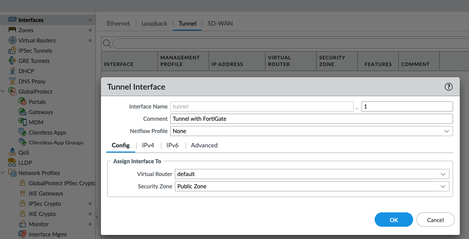
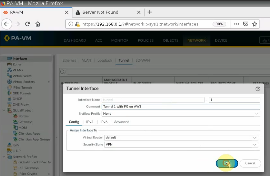
On PA, Configure a tunnel.
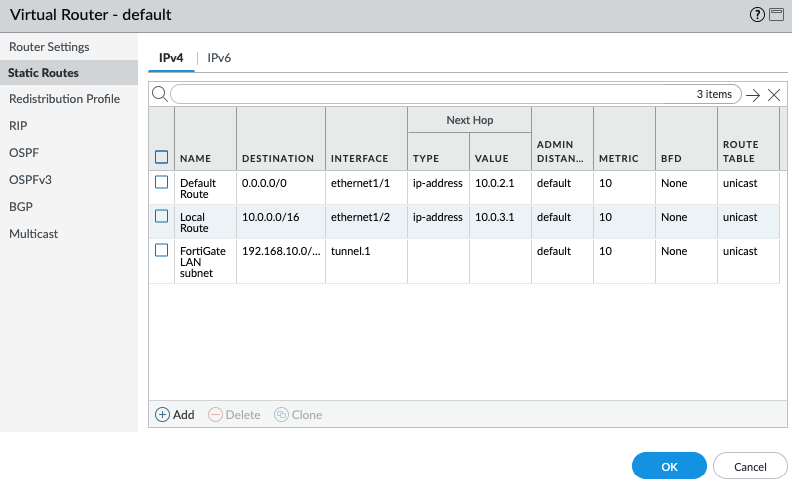
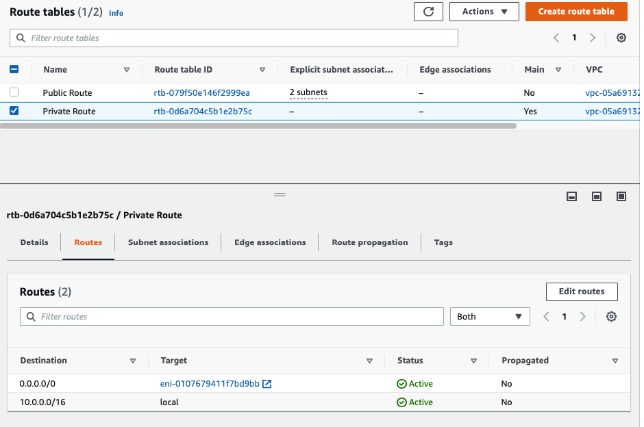
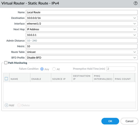
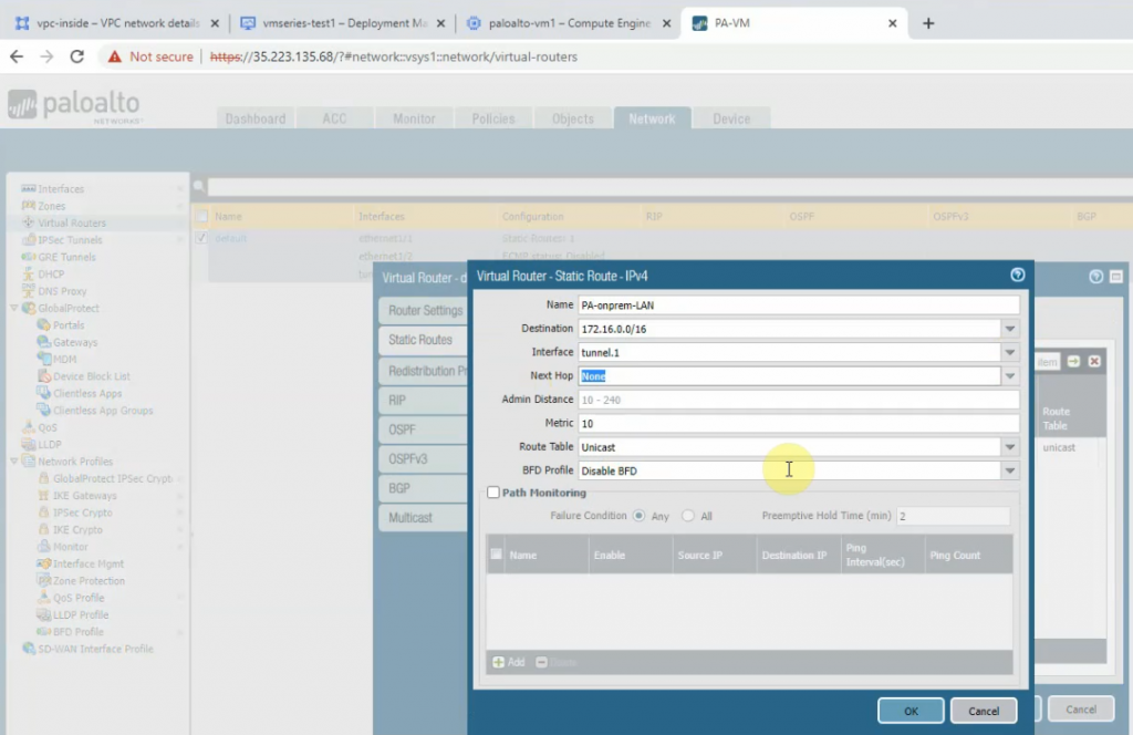
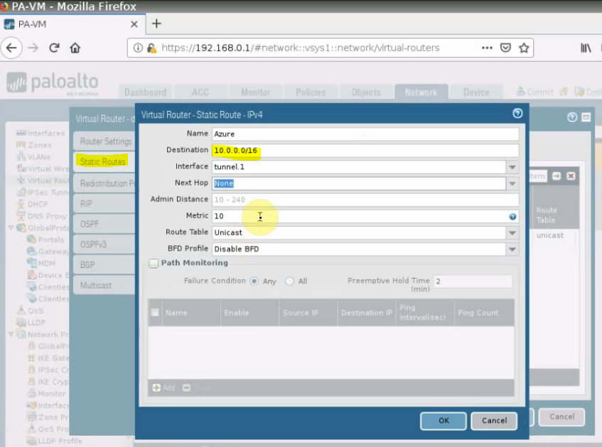
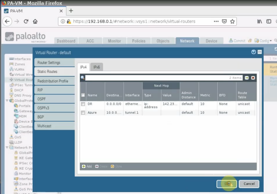
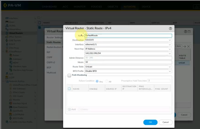
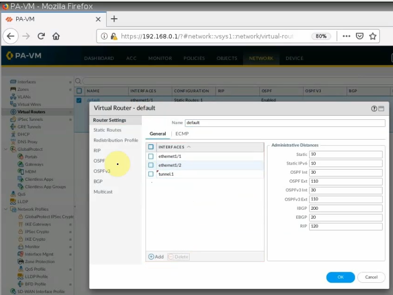
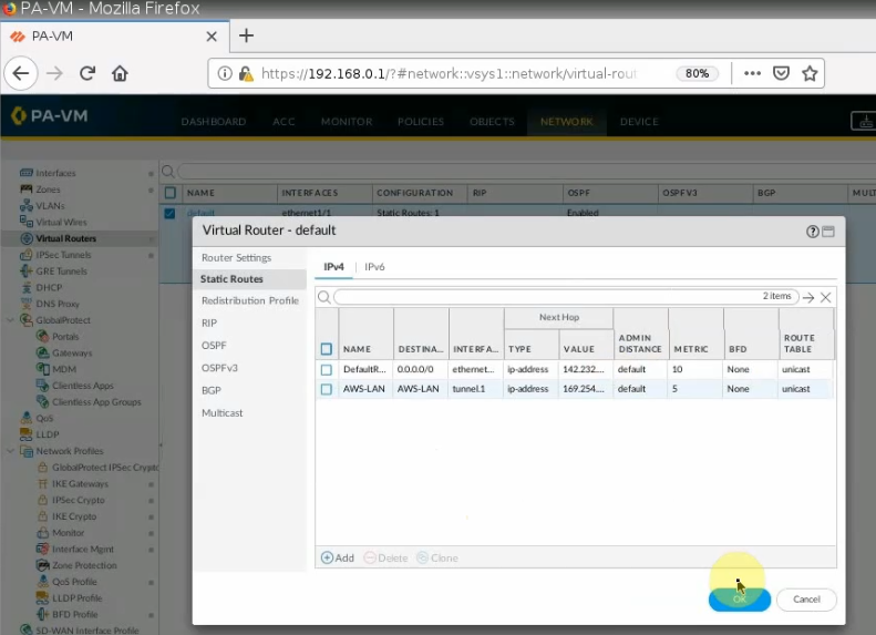
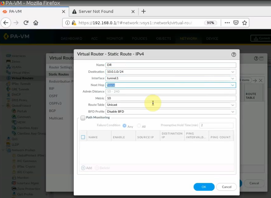
Add a new static route into PA Virtual Route to allow traffic from the Private subnet to a LAN subnet in FortiGate.
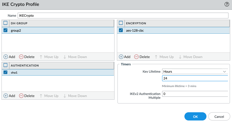
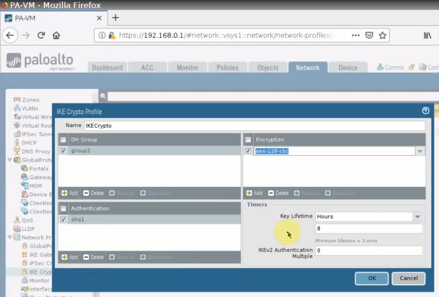
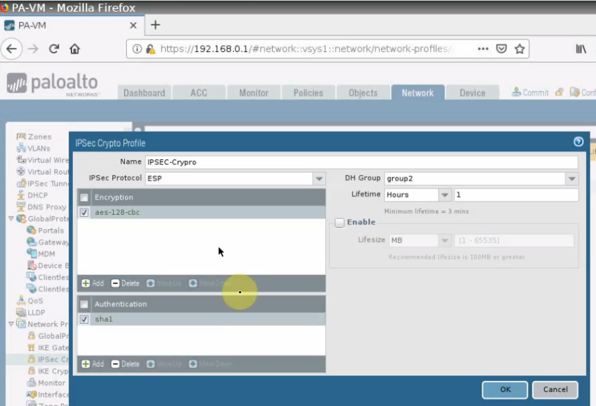
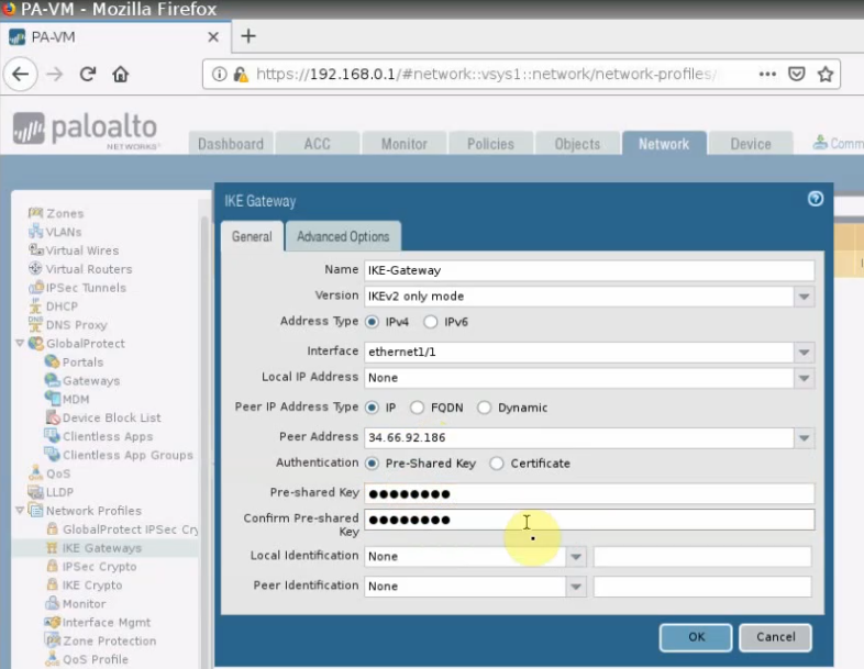
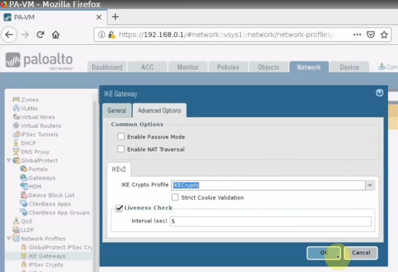
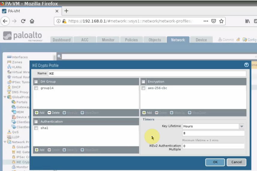
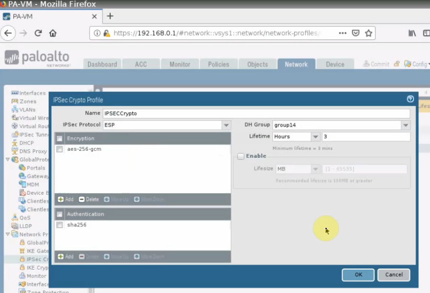
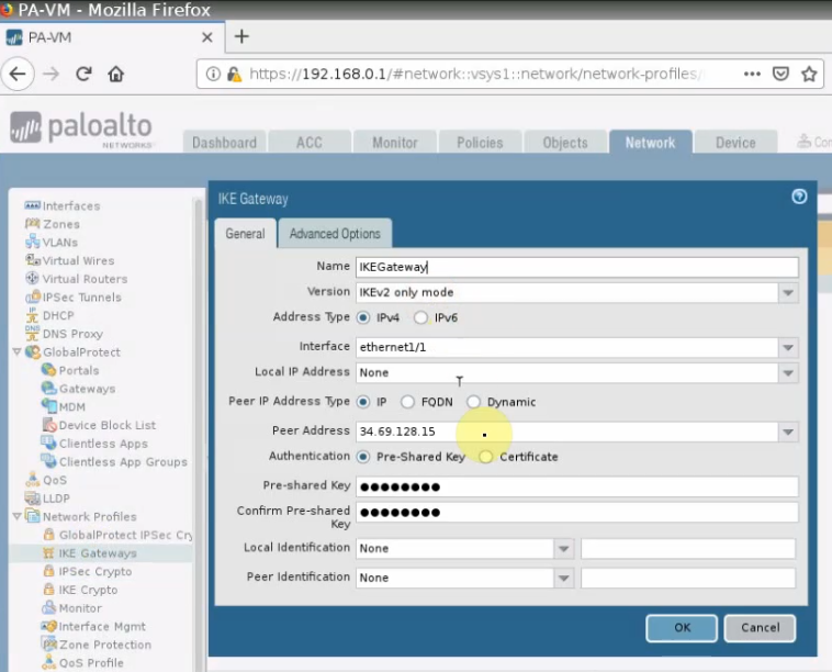
Create IKE Crypto.Create IPSEC Crypto.Create an IKE Gateway.
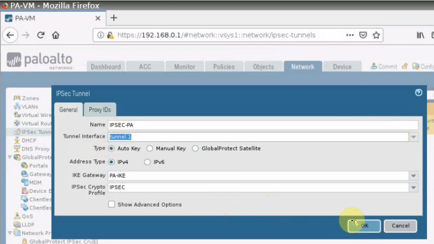
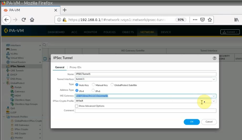
Create an IPSEC tunnel.
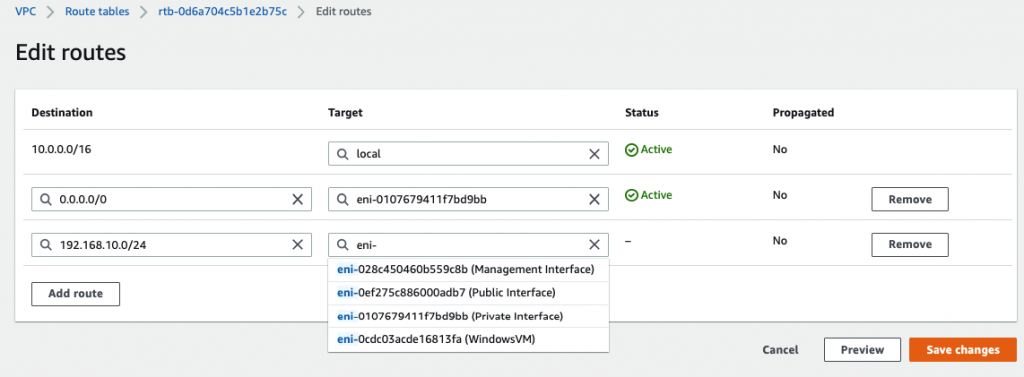
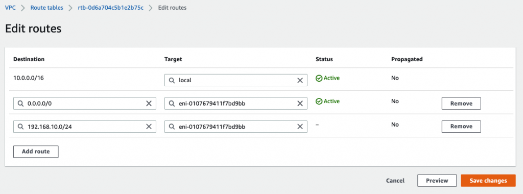
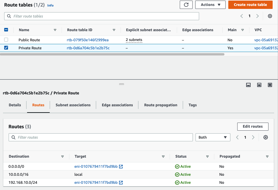
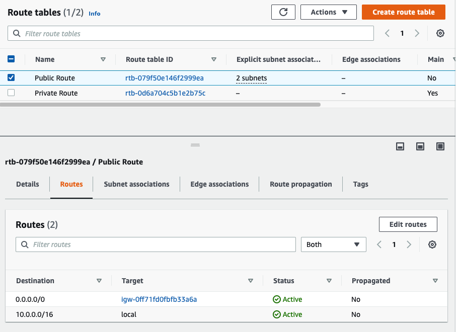
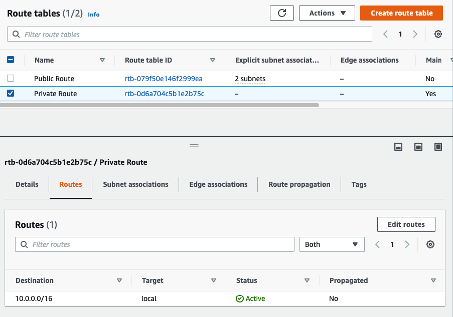
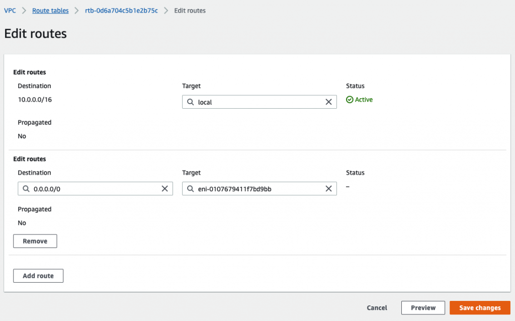
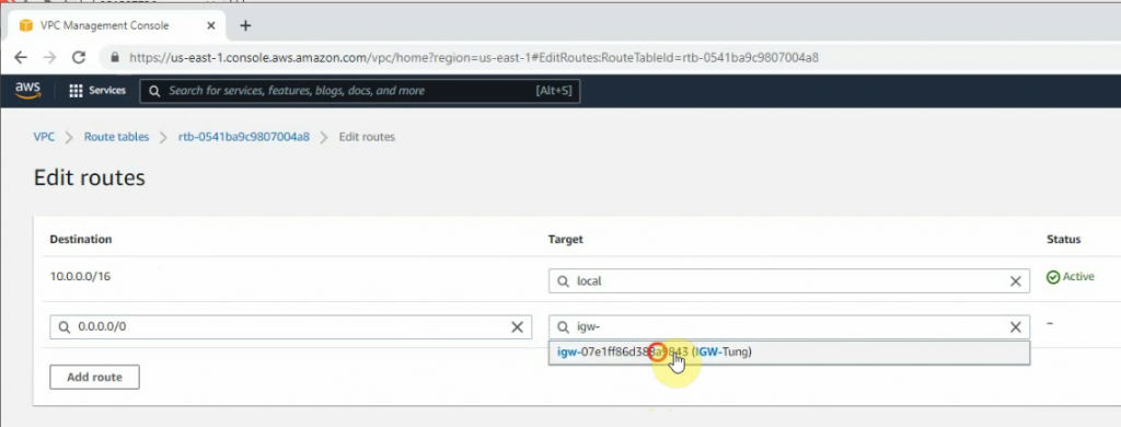
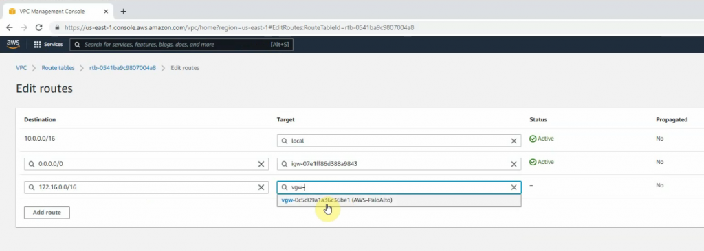
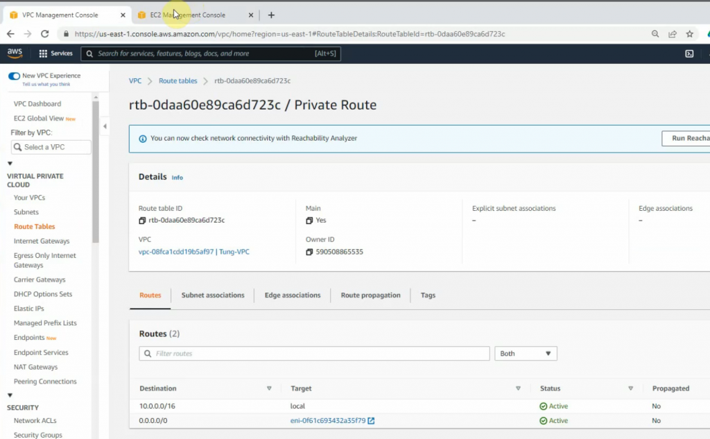
Create PA-LAN and FG-LAN network.Create both Security rules to allow traffic from PA-LAN to FG-LAN and vice versa.Back to AWS – Route tables. Add a new static route on the Private Route.
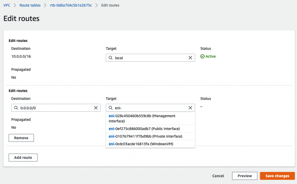
Add 192.168.10.0/24 into the routes and select “Private Interface” on the target.
Move on to FortiGate.
Configure interfaces.
Configure default routes on FG.
Configure IPSEC VPN on FG.
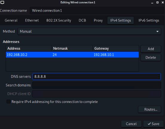
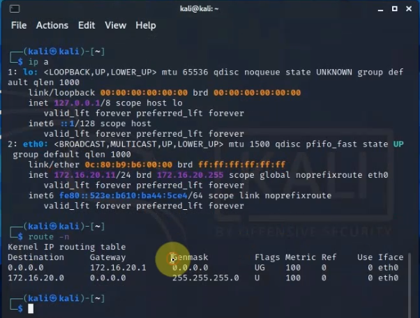
Create a FG-LAN and PA-LAN address.Set up a new static route to allow traffic from FG-LAN subnet in FG to PA-LAN subnet in AWS.Create Security Polices to allow traffic from FG-LAN to PA-LAN and vice versa.Setup IP address on Kali machine.
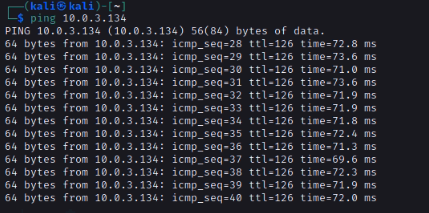
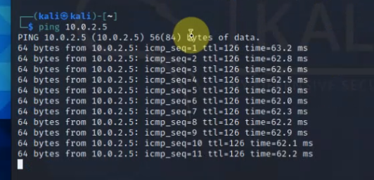
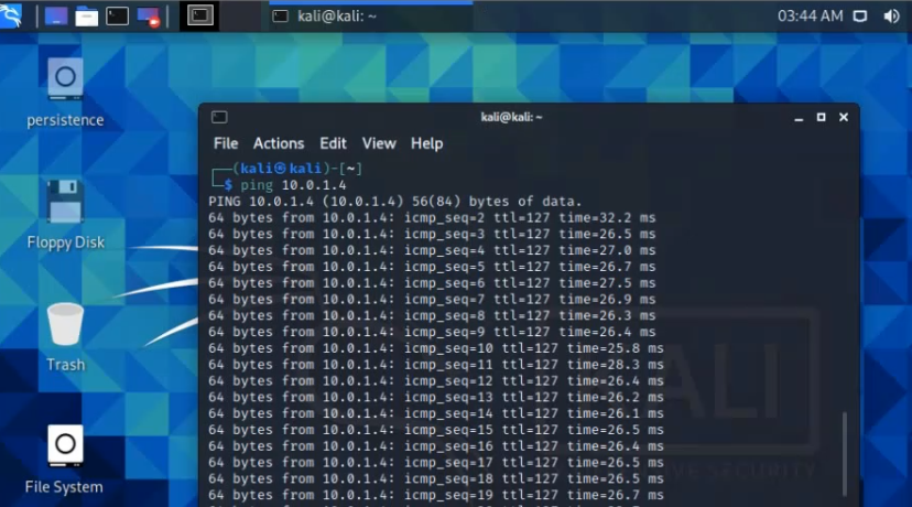
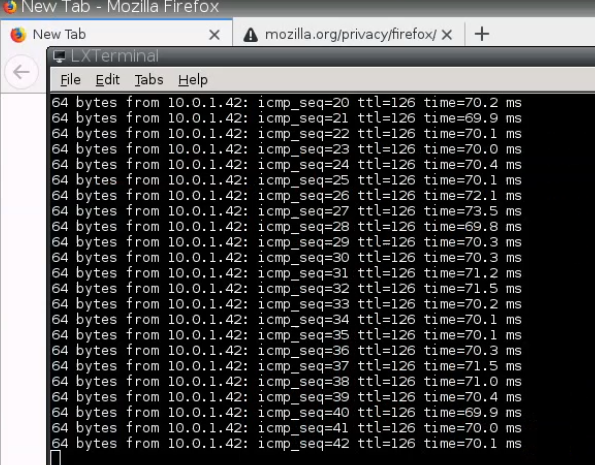
Ping from Kali machine to Windows instance (10.0.3.134).
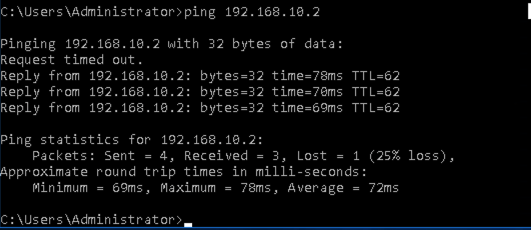
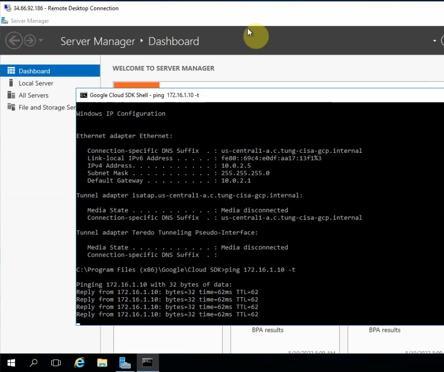
Ping from Windows instance to Kali machine (192.168.10.2).
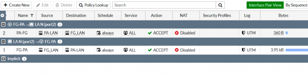
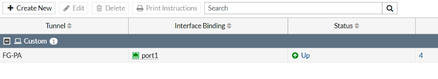
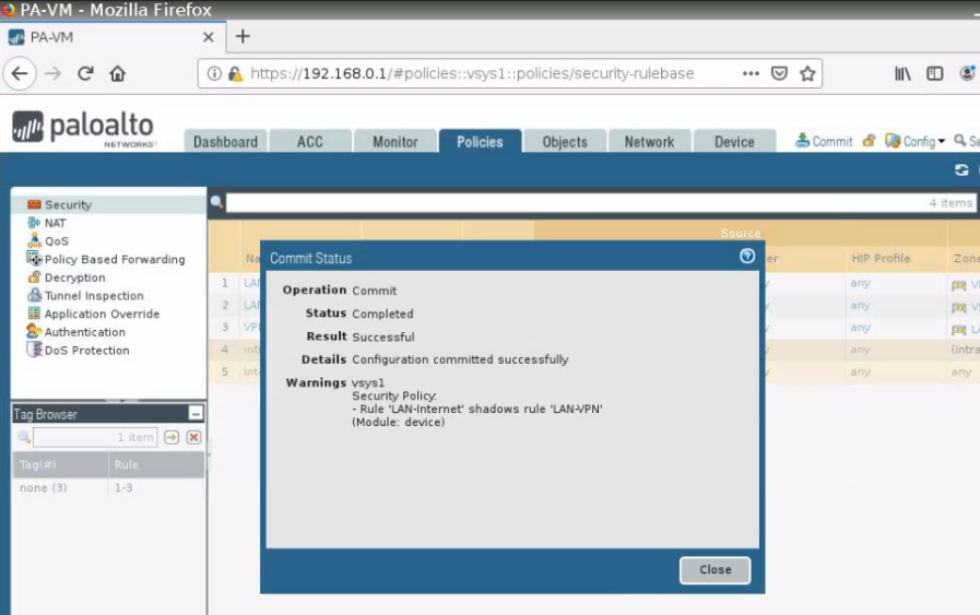
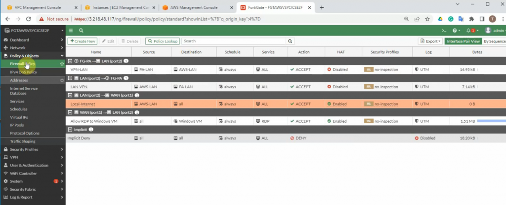
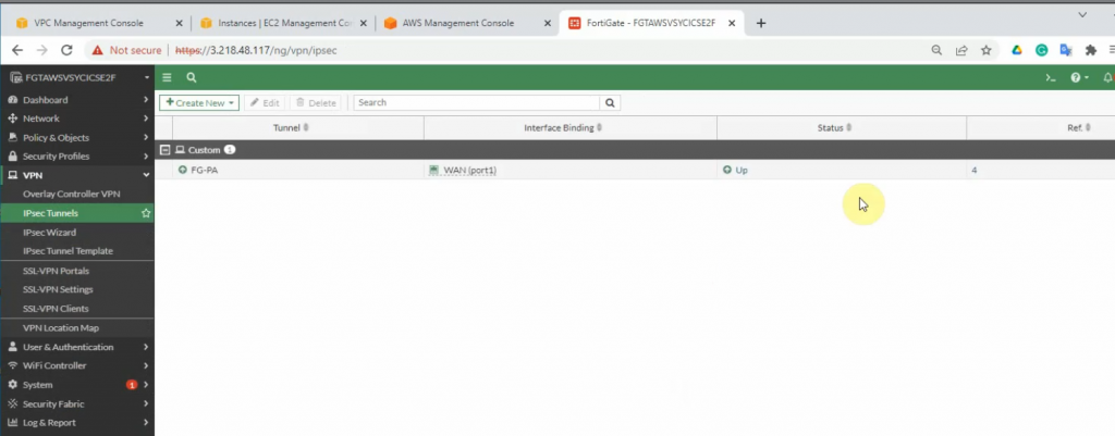
Check Security Policy status.The FortiGate IPSEC tunnel is UP.
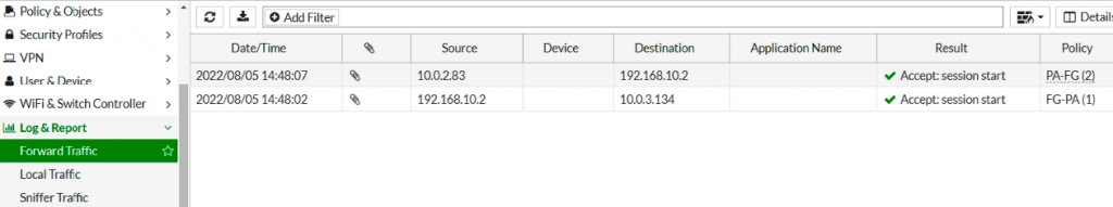
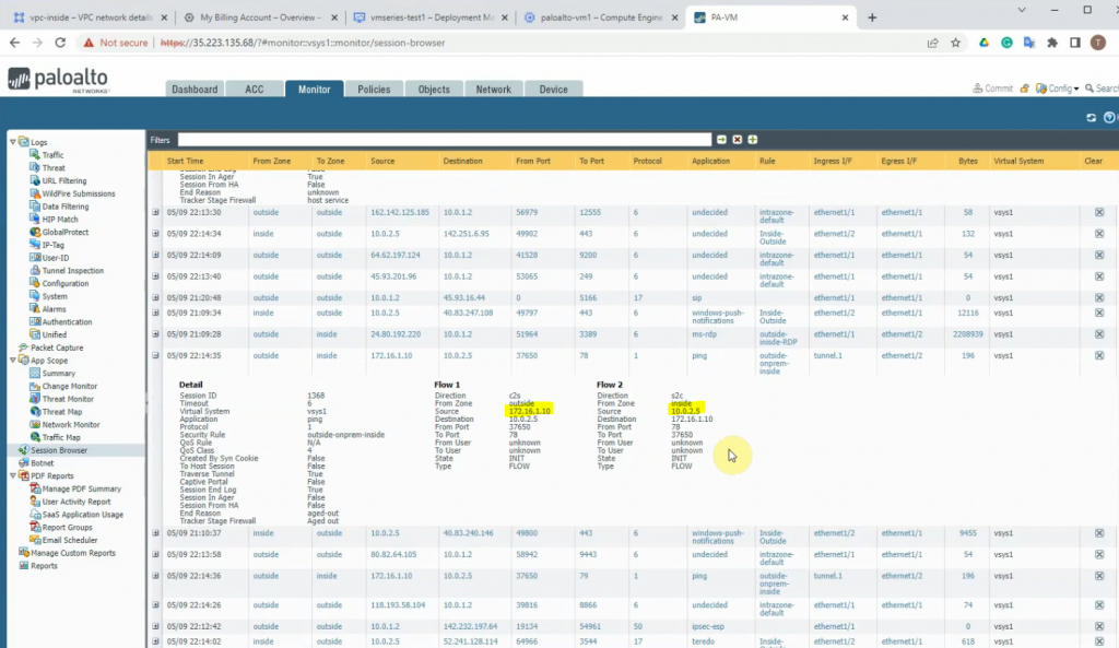
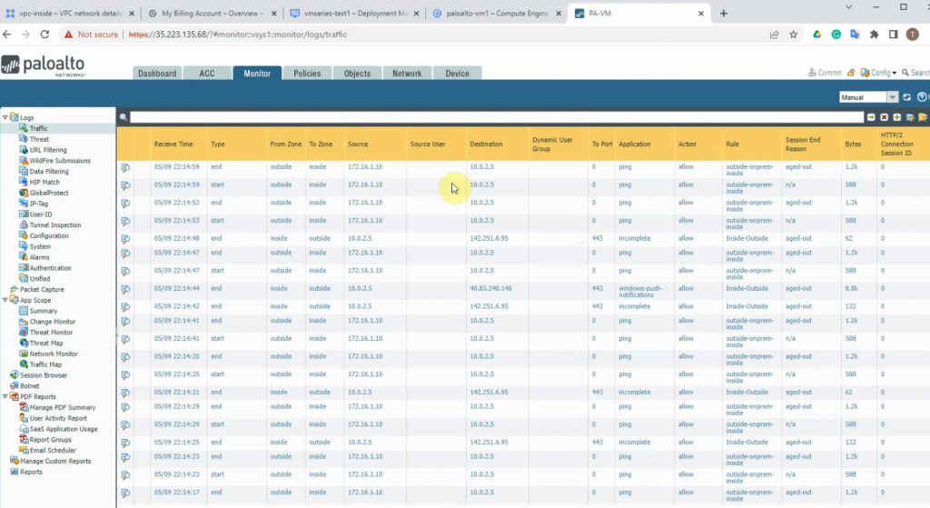
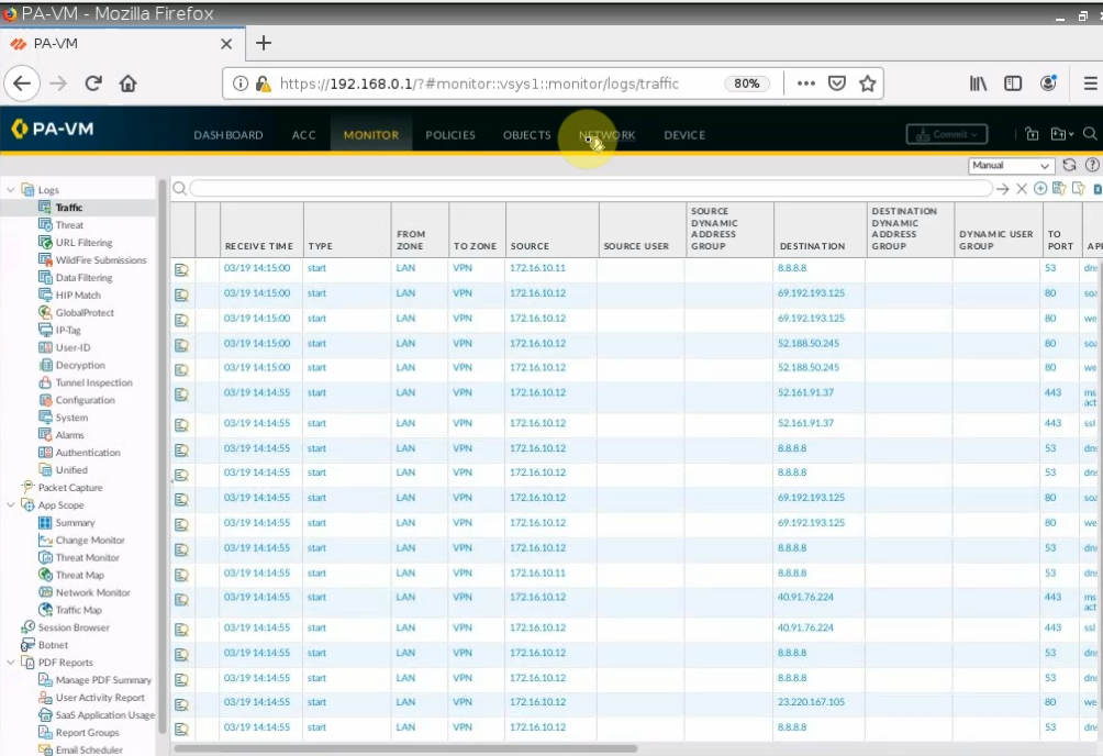
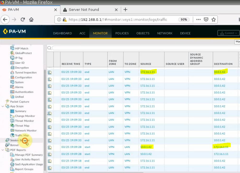
Back to Palo Alto in AWS. We can see the traffic from PA-LAN to FG-LAN and vice versa.
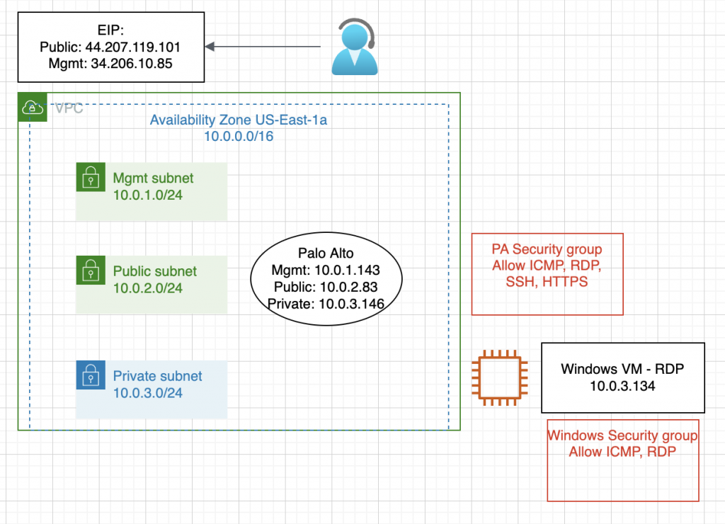
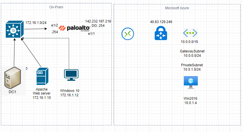
This is a diagram that is used to deploy this lab.
Below are a couple of steps to deploy Palo Alto on AWS
Create a key pair, VPC, subnets, Internet Gateway, Route tables
Create a Palo Alto instance on AWS
Create Elastic IP addresses for Management and Public interface
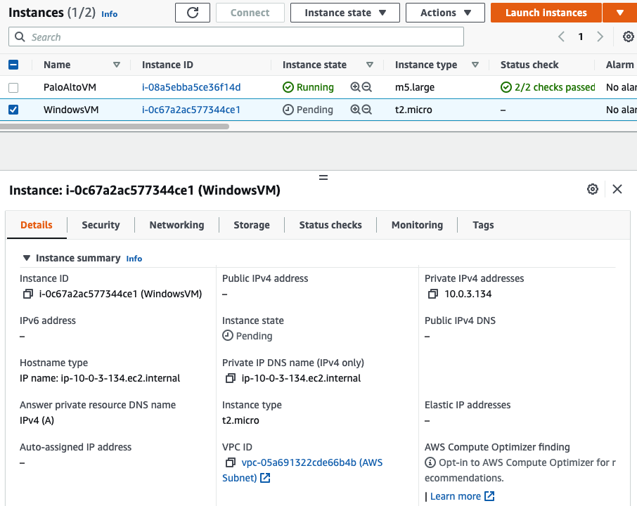
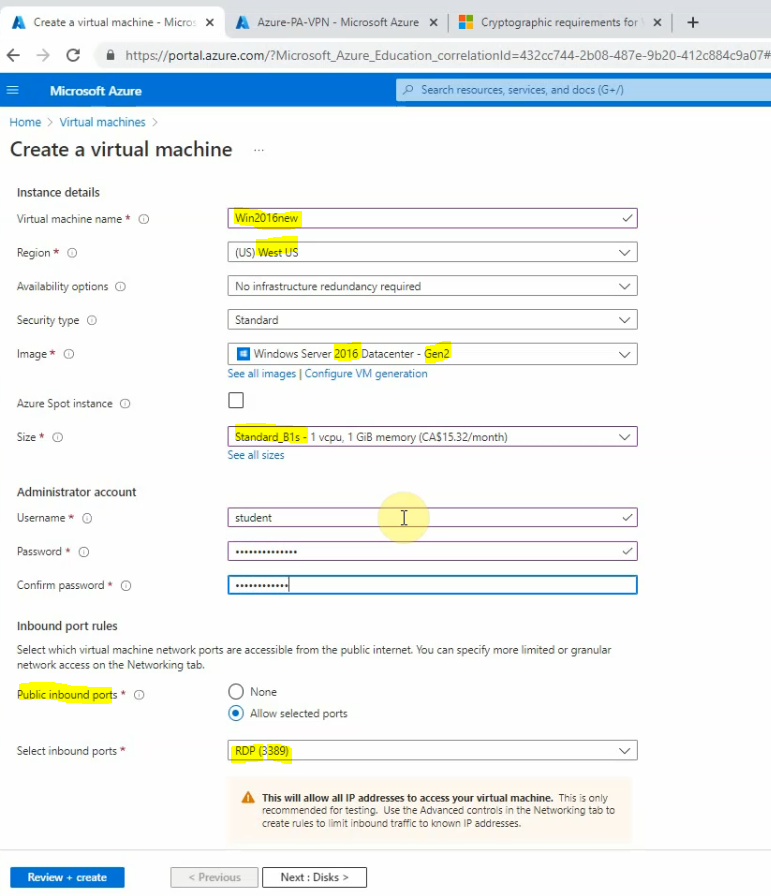
Create a Windows VM on private subnet
Modify Security Group to allow traffic from the Internet to PA and Windows VM
Configure a Security Policy, NAT to allow traffic from the Internet to the Windows VM via RDP
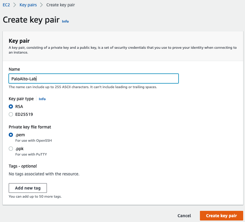
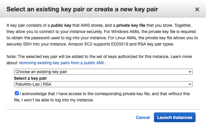
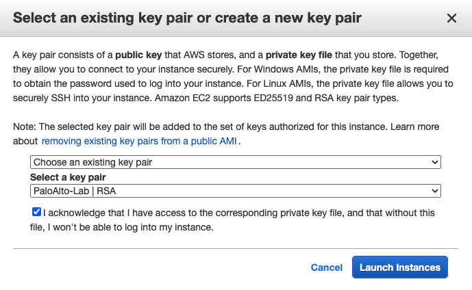
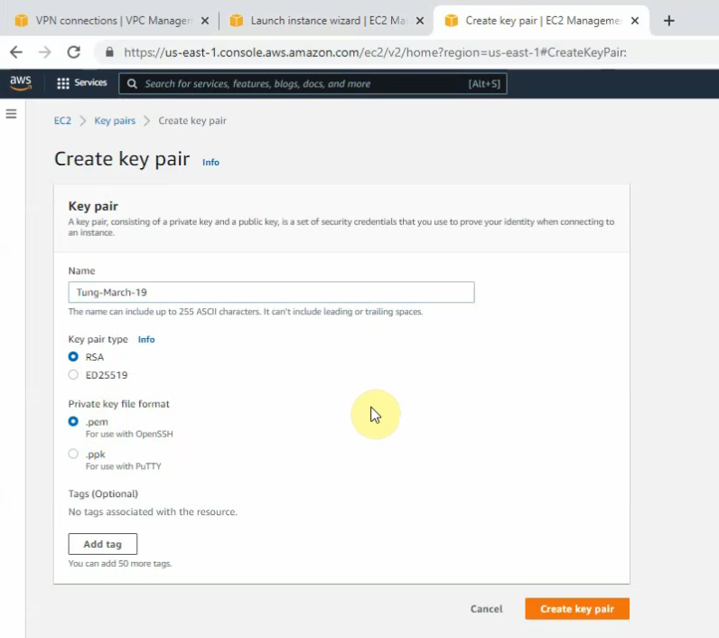
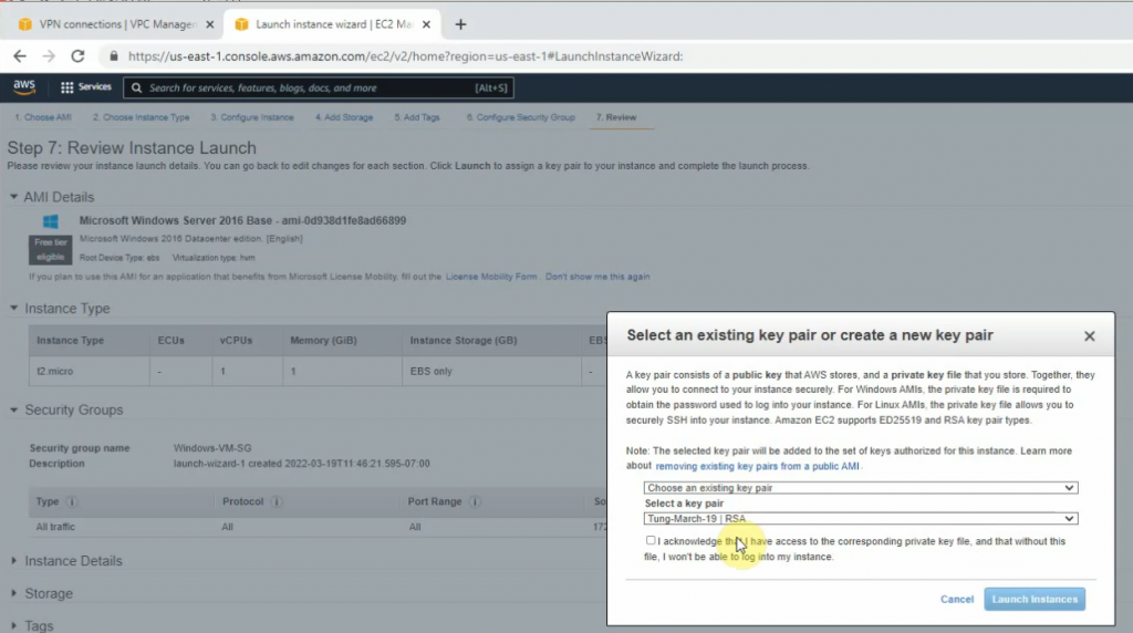
Create a key pair.
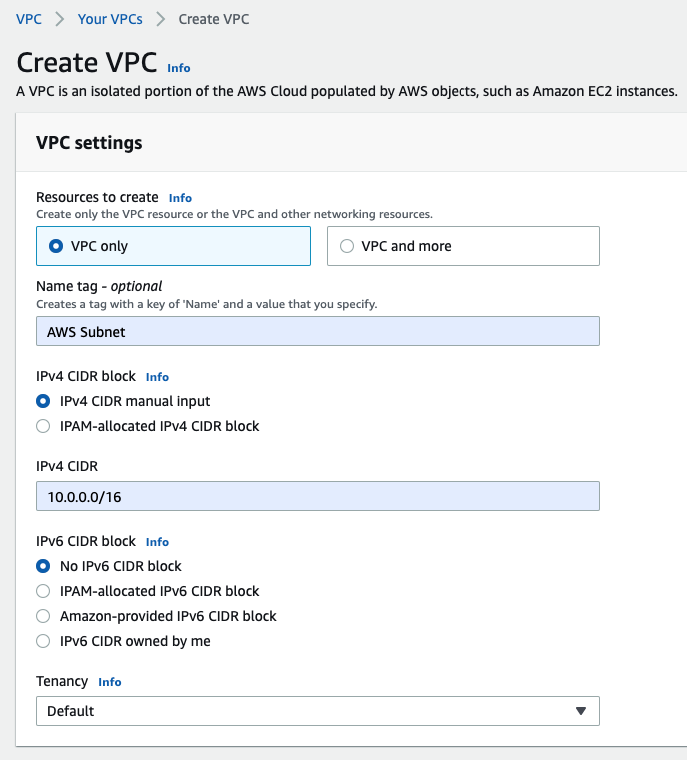
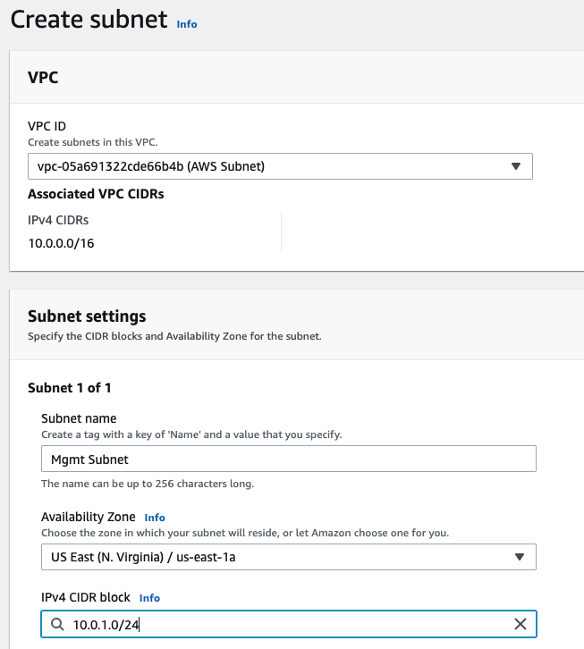
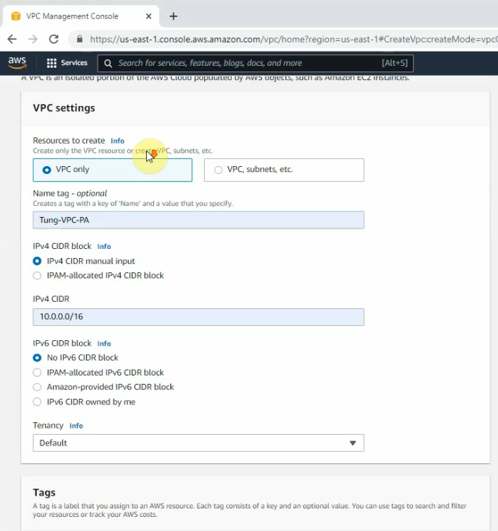
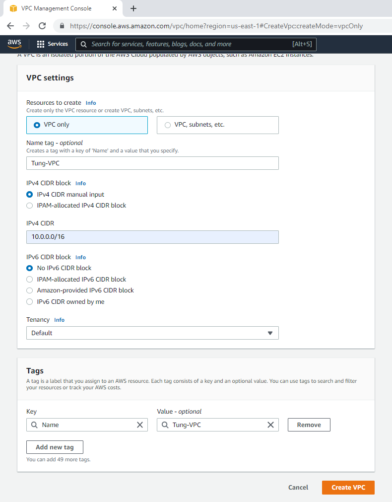
Create a VPC.Create a management subnet.
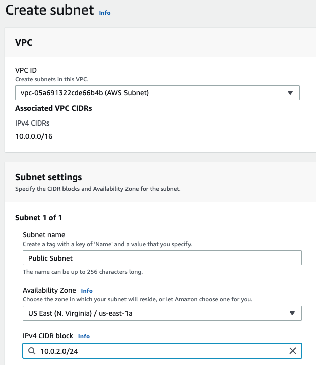
Create a Public subnet on availability zone US-East-1a. I got an error that I cannot create a Palo Alto if my VPC is randomly used US-East-1e.
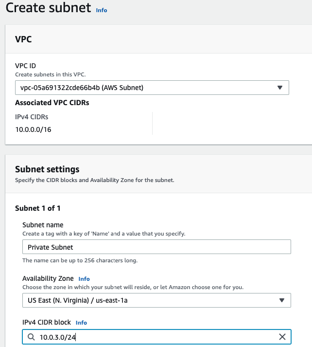
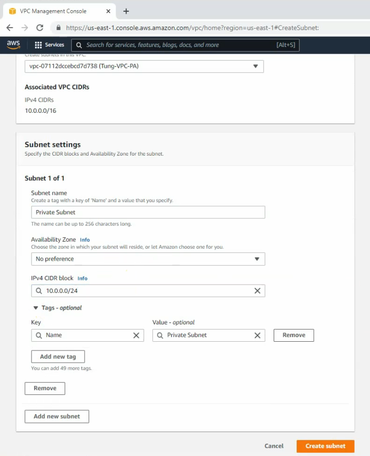
Create a Private subnet.
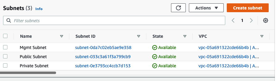
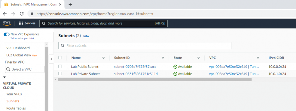
There are 3 subnets on AWS Subnet VPC.
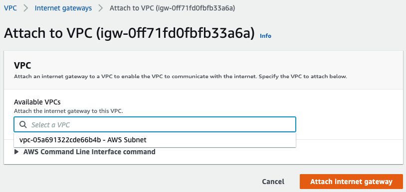
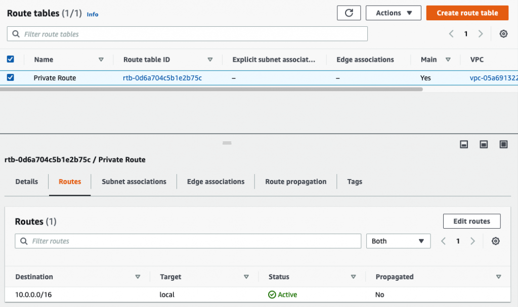
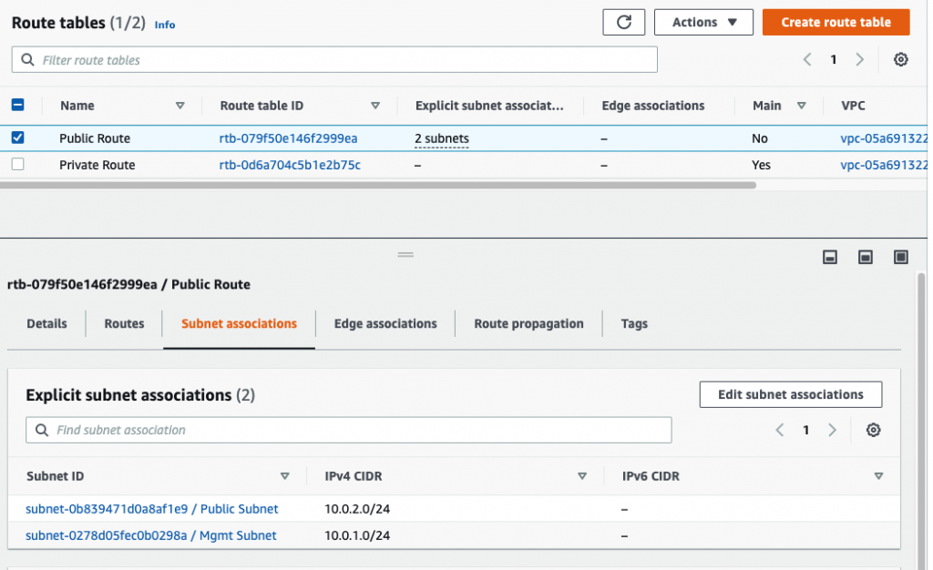
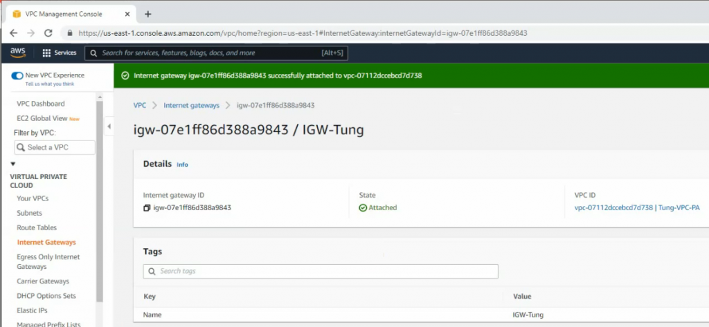
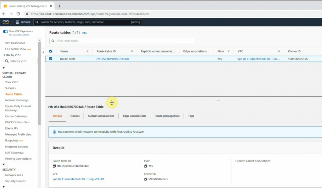
Create a Internet Gateway and attach it into your VPC.Rename Route table to Private Route
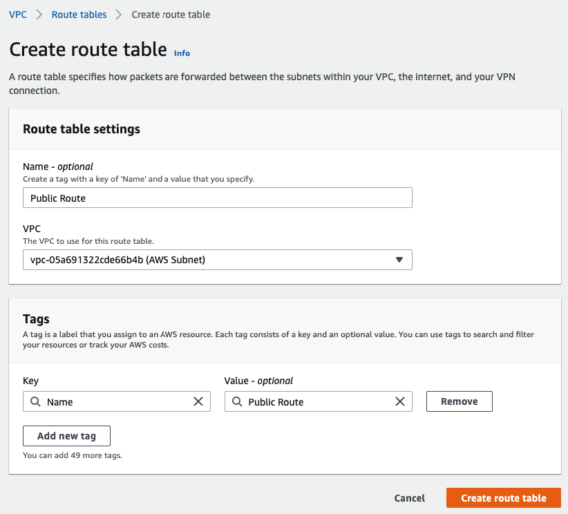
Create a Public Route table.
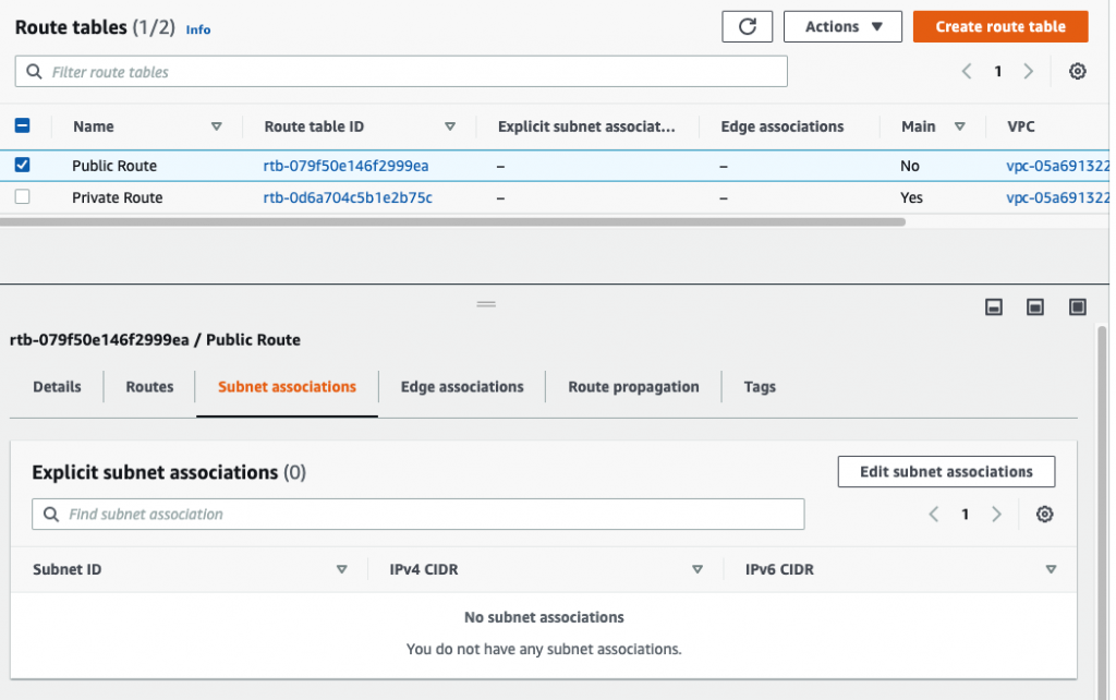
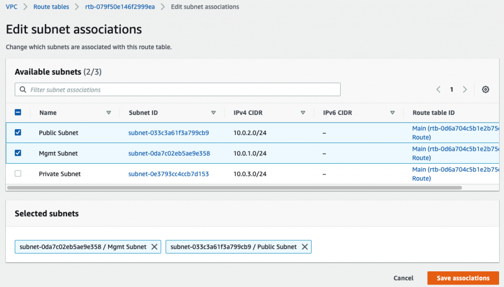
Associate Management and Public Subnet to Public Route table.
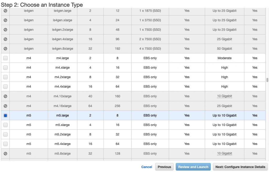
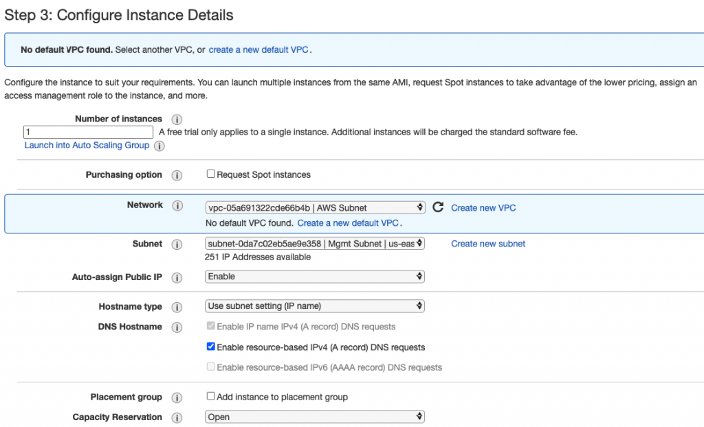
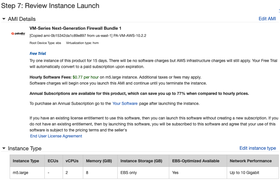
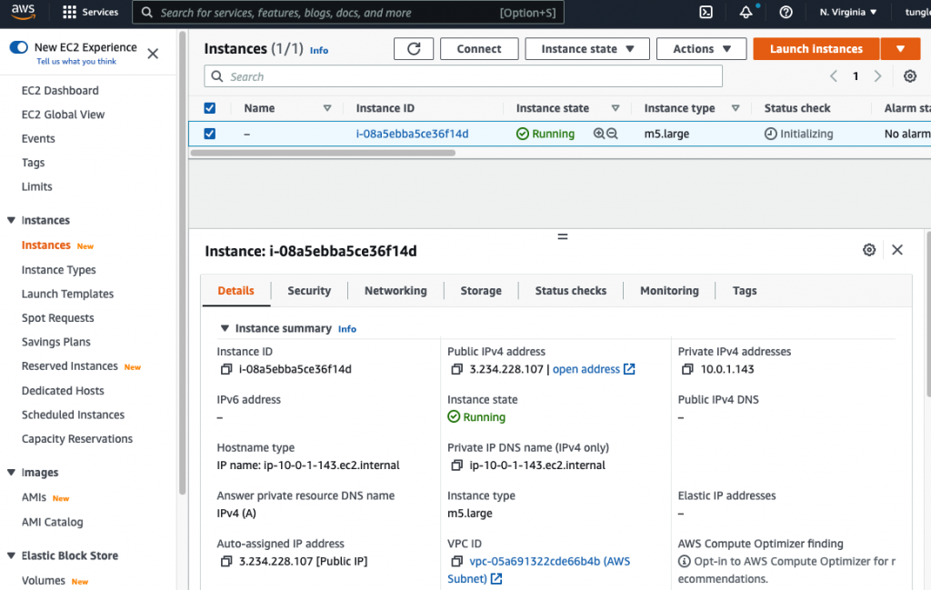
Launch a Palo Alto Firewall on AWS.
Select “Management Subnet” in the Subnet setting.
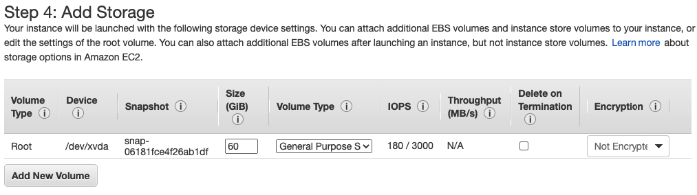
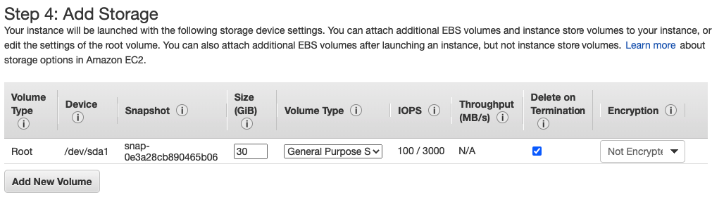
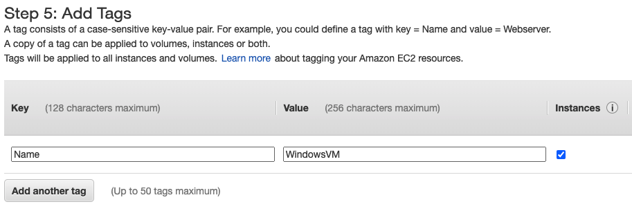
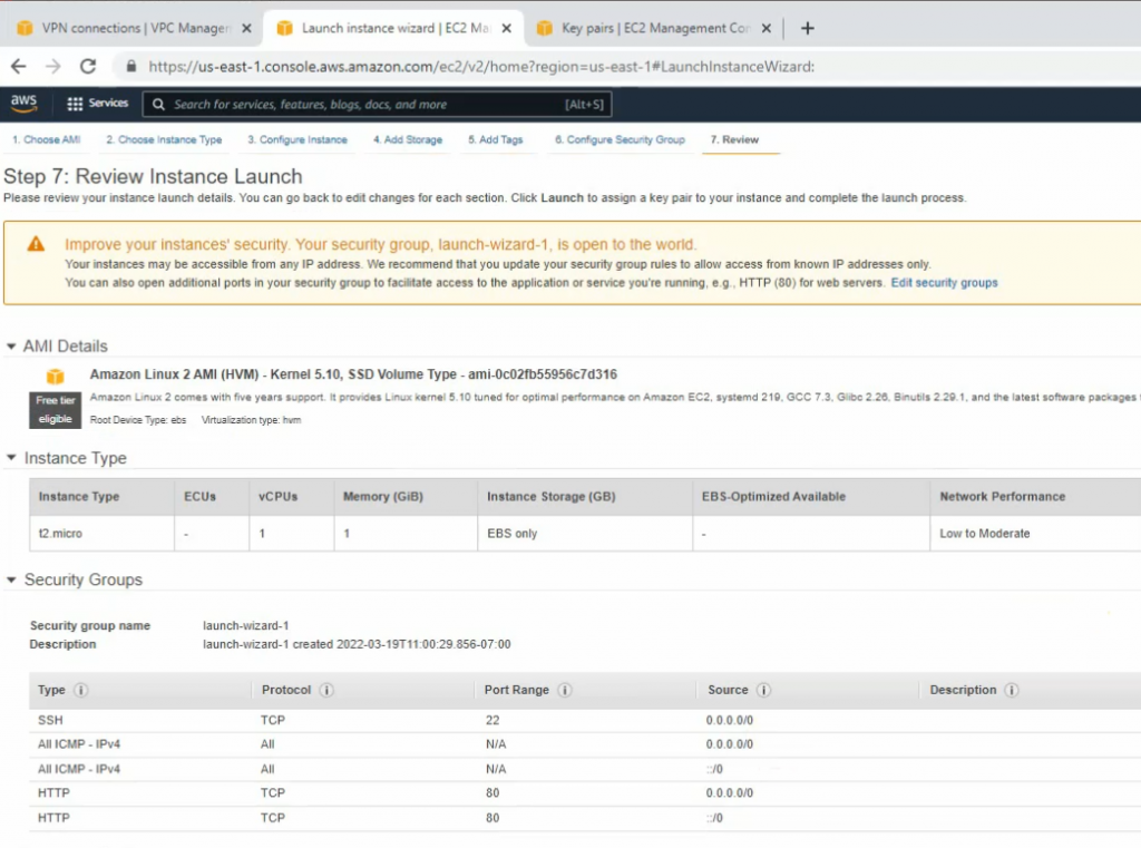
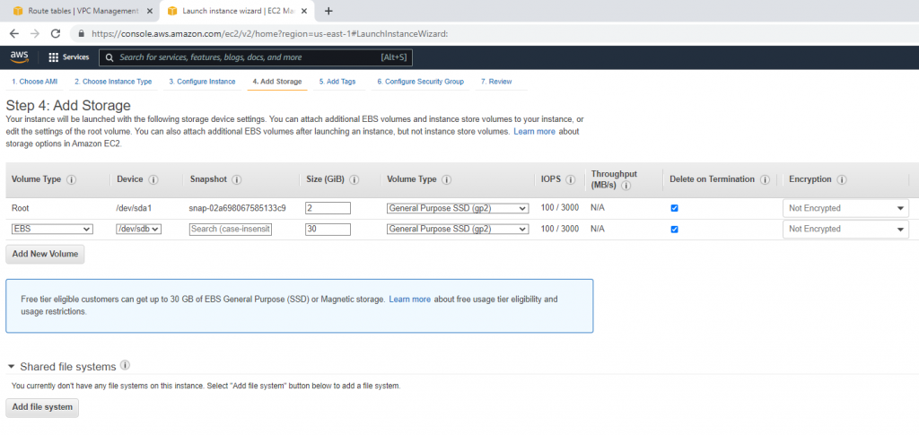
Leave “Add Storage” and Tags as default.
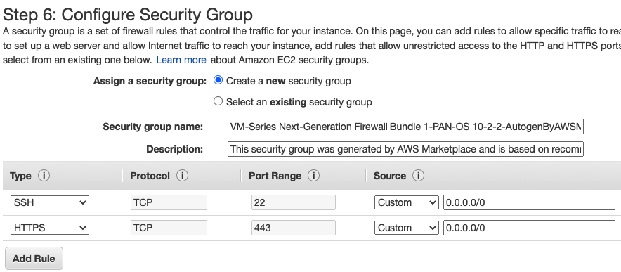
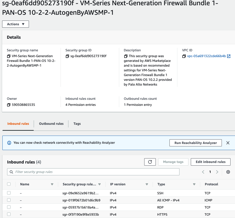
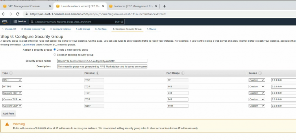
Use a Security Group that has been generated automatically when creating the PA VM.
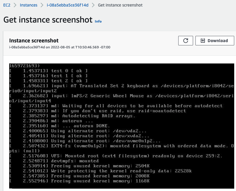
Actions – Monitor – get instance screenshot.
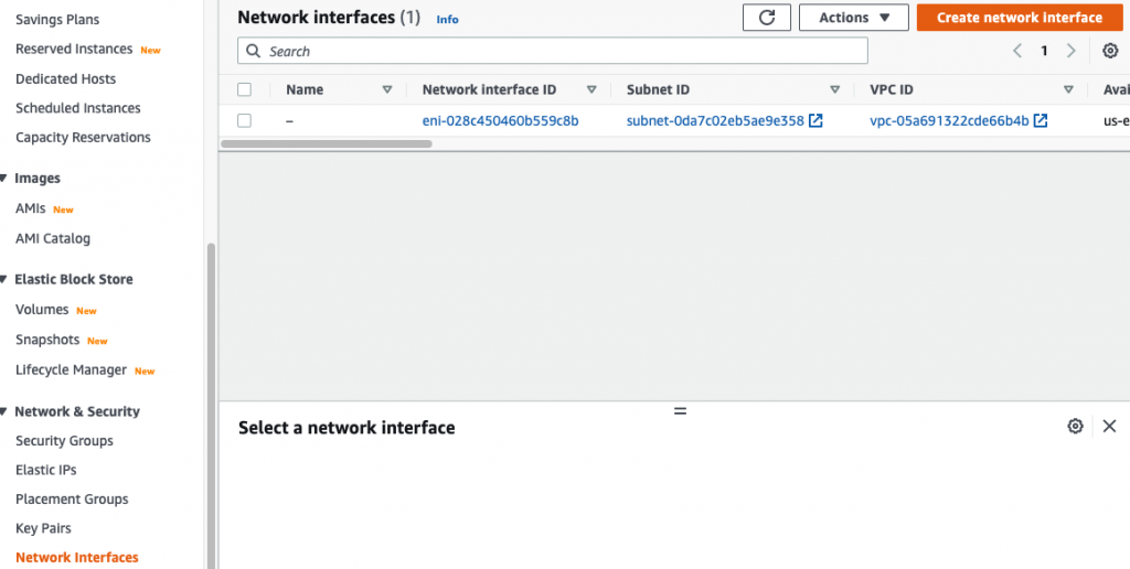
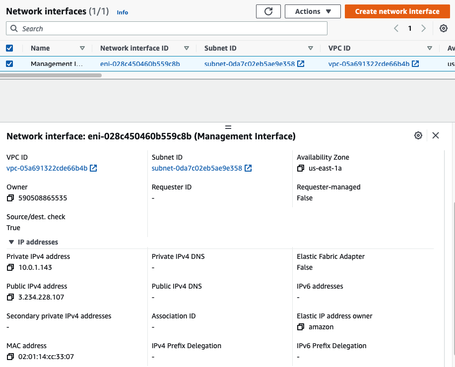
Go to EC2 – Network interfaces. Rename a name of the “-” to “Management interface”.
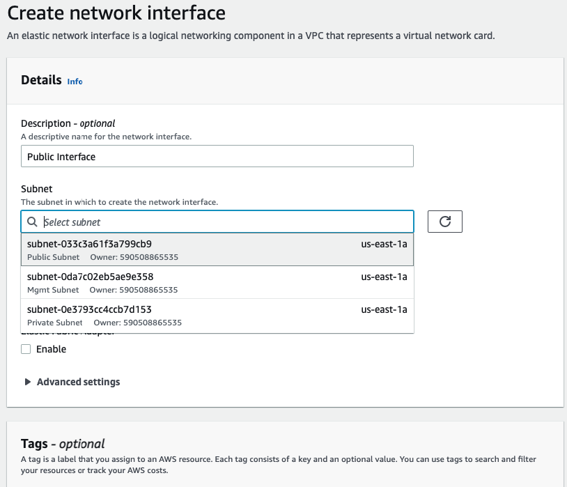
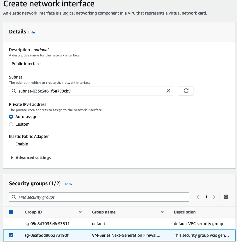
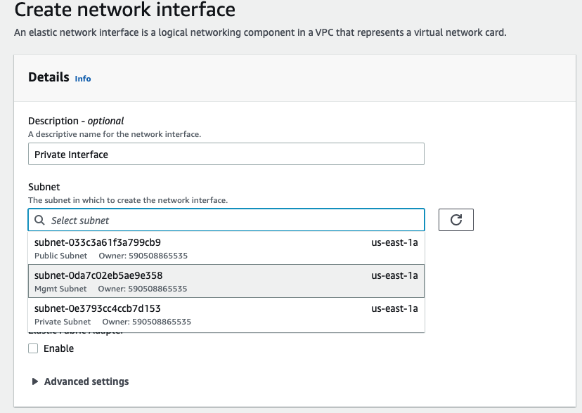
Create a Public interface of PA and link it to the “Public Subnet”.
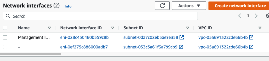
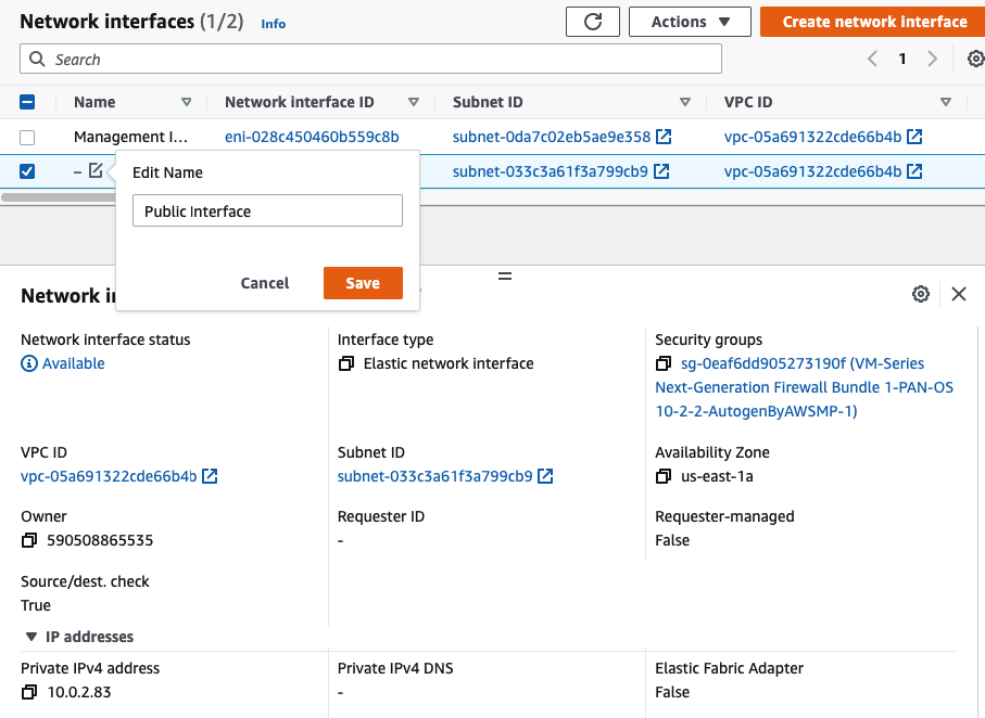
Rename a name of the “-” to “Public interface”.
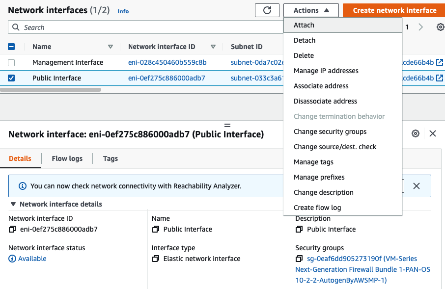
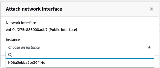
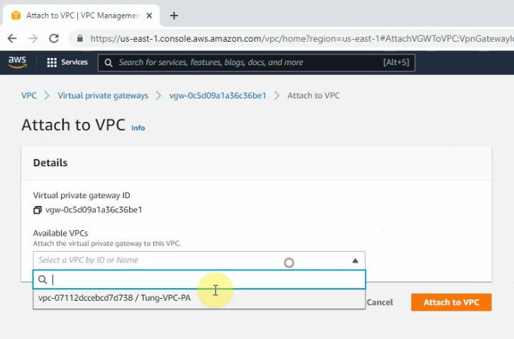
Attach it into PA.
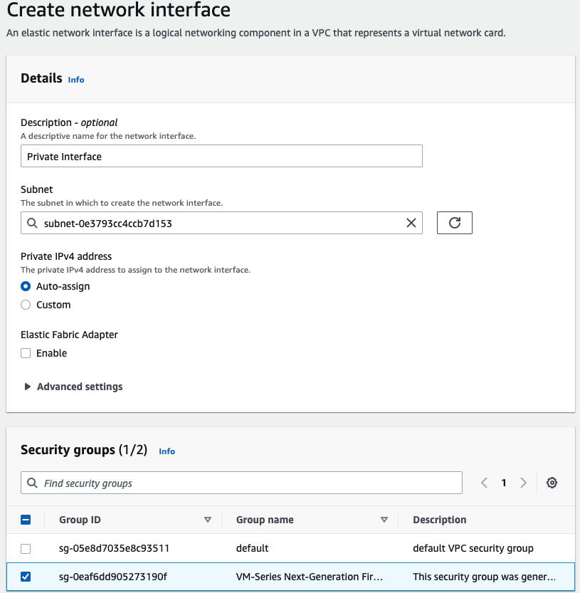
Create a Private interface of PA and link it to the “Private Subnet”.
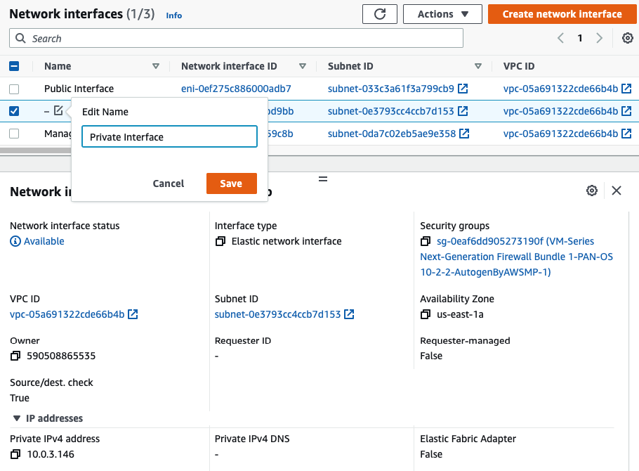
Rename a name of the “-” to “Private interface”.
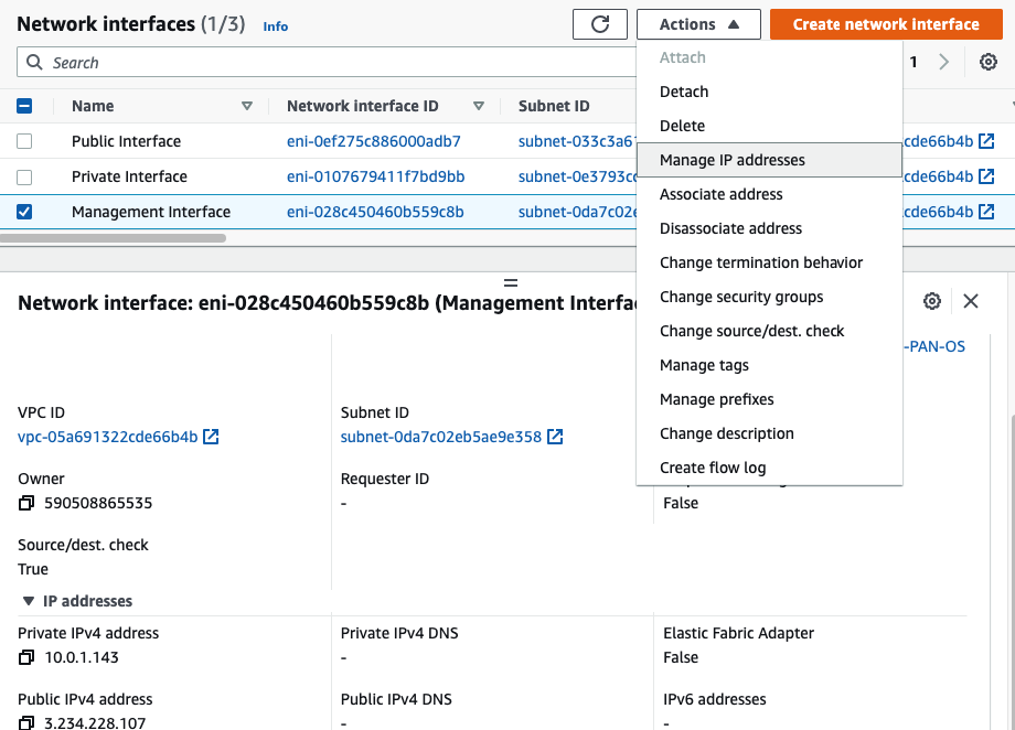
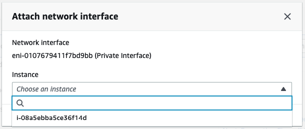
Attach the Private interface into PA.
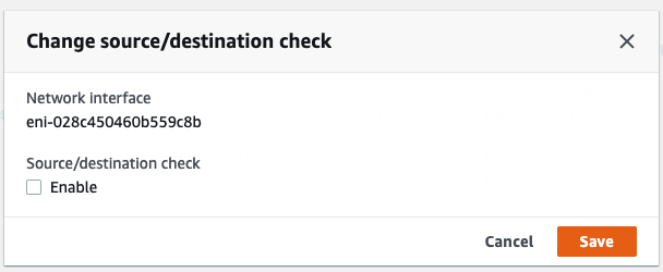
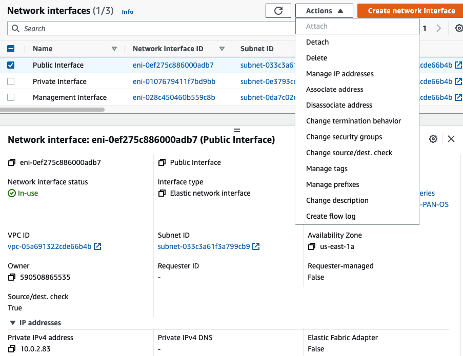
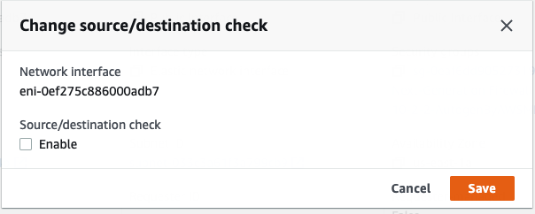
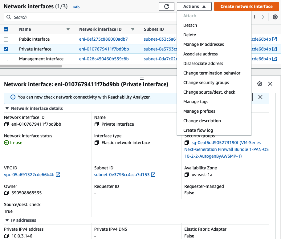
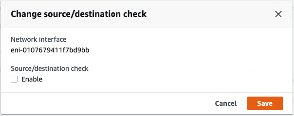
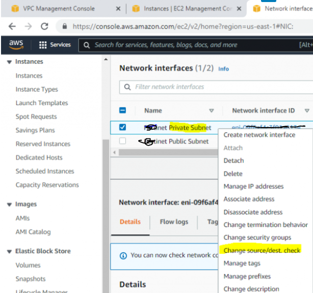
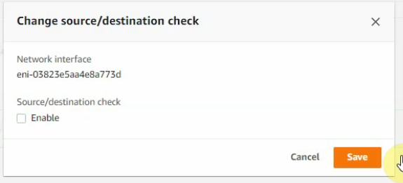
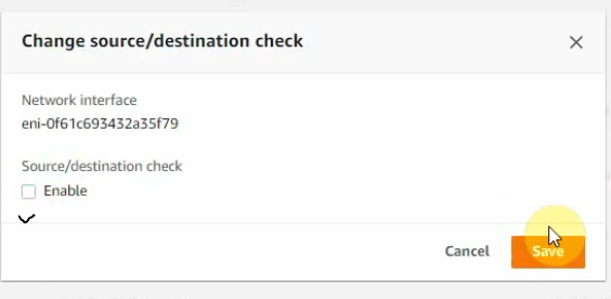
Disable “Change source/dest. check” in all interfaces.
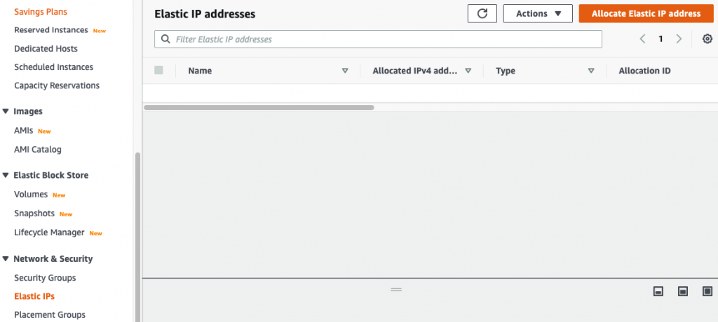
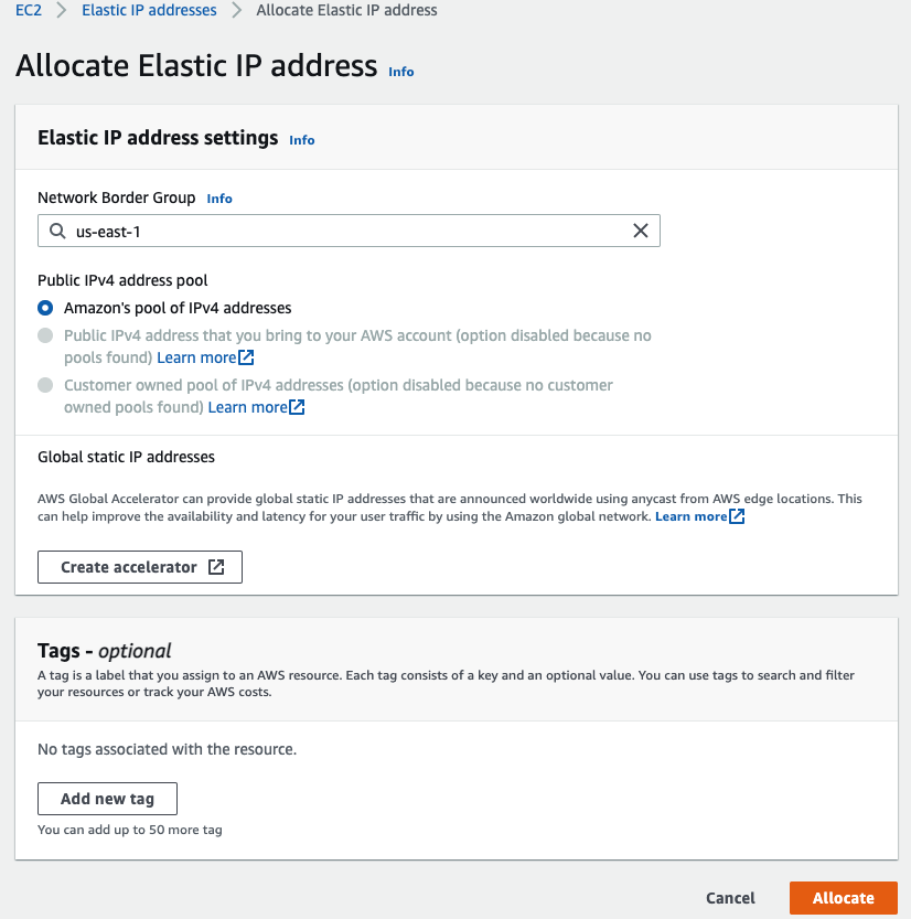
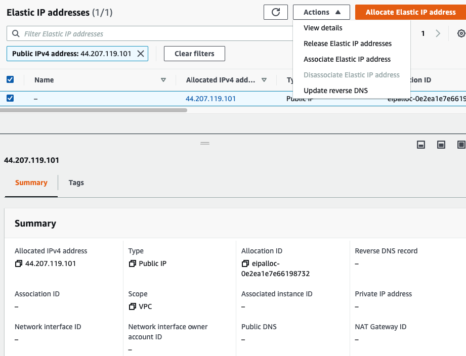
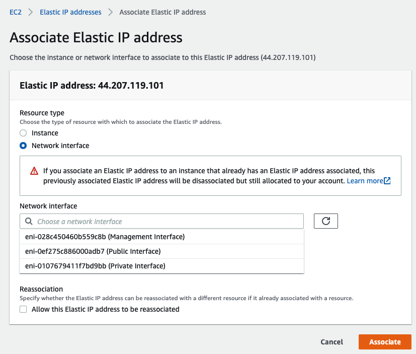
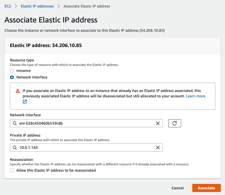
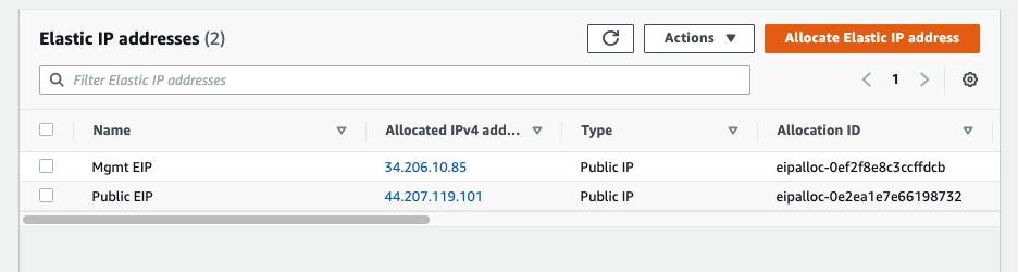
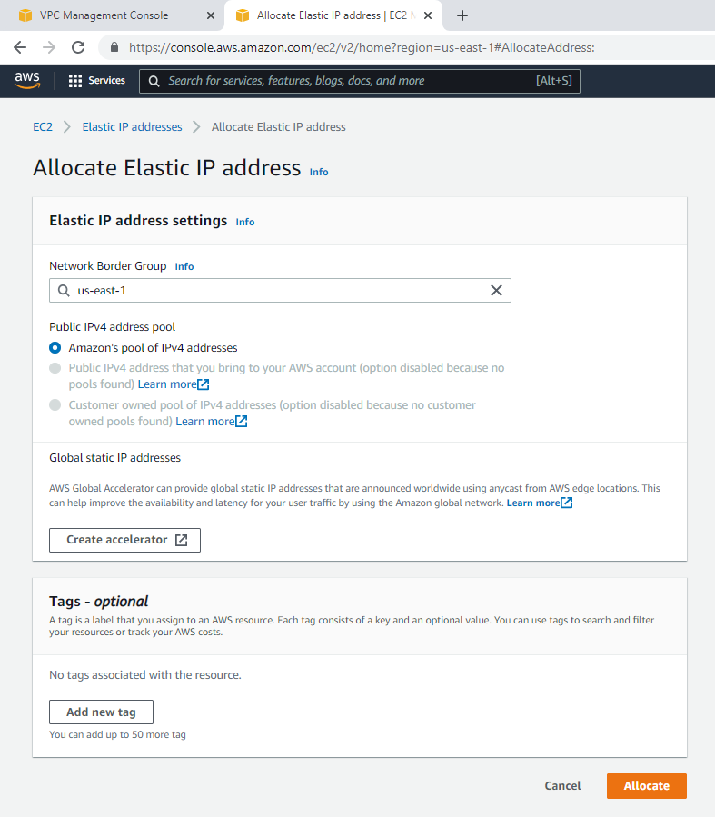
Assign two Elastic IP addresses for Public interface.Associate EIP to Public interface.
Select “Public interface”
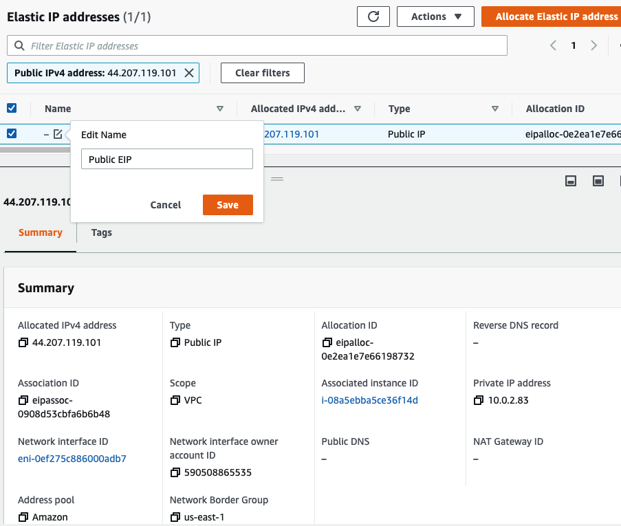
Rename “-” to Public EIP.
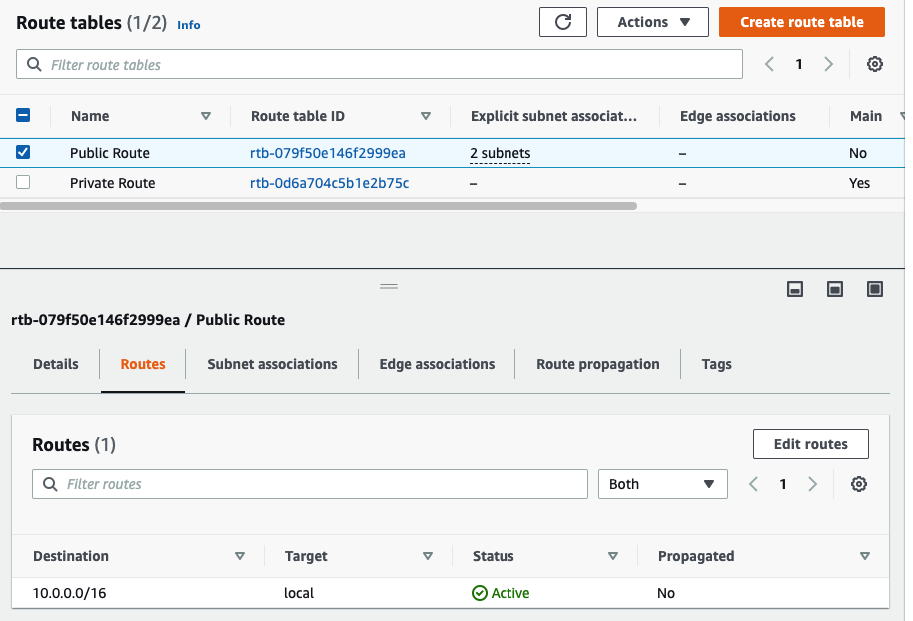
Back to Route table,
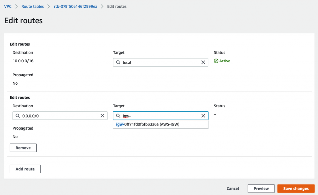
Create a default route via Internet Gateway.
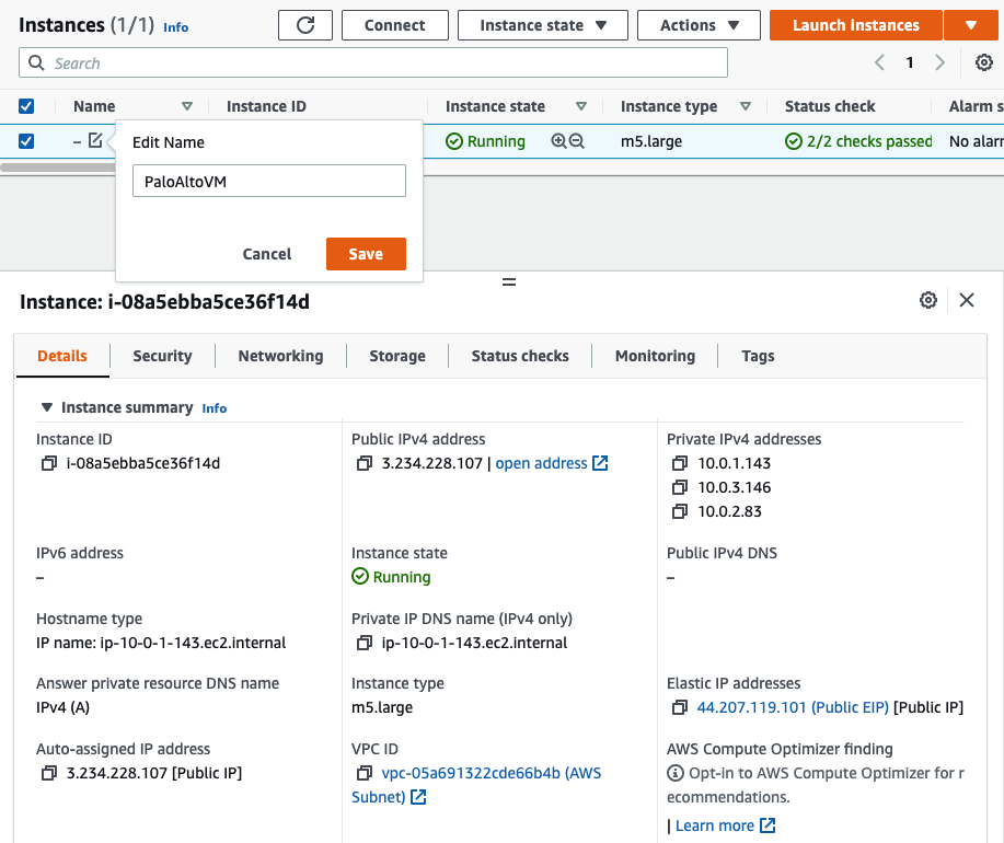
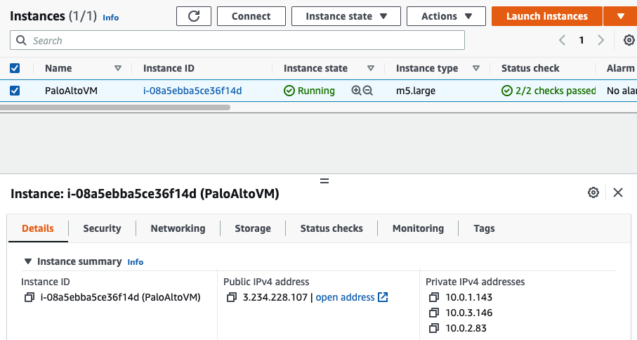
Back to PA instance, rename it into PaloAltoVM.
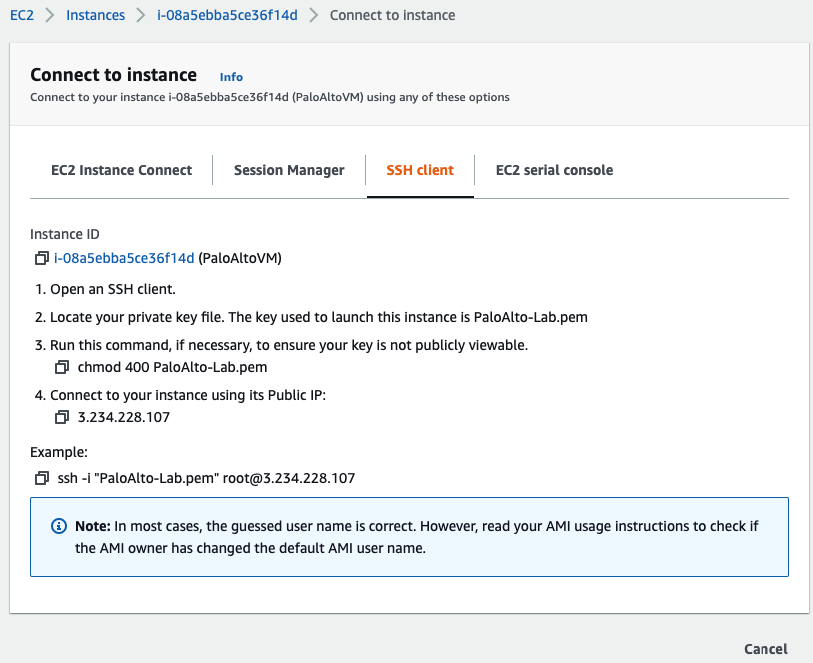
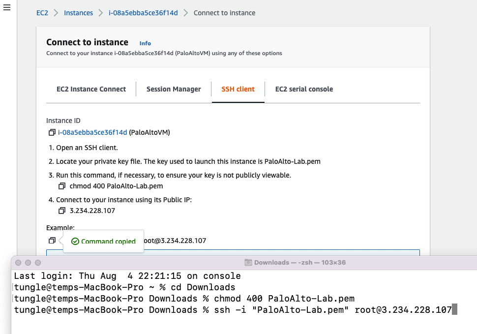
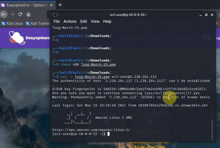
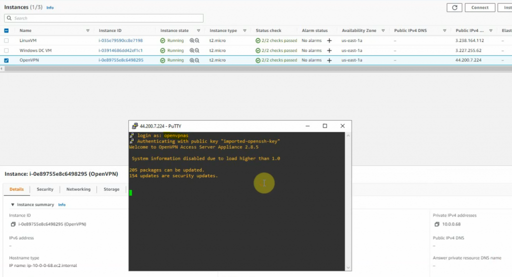
Access SSH to Palo Alto instance.
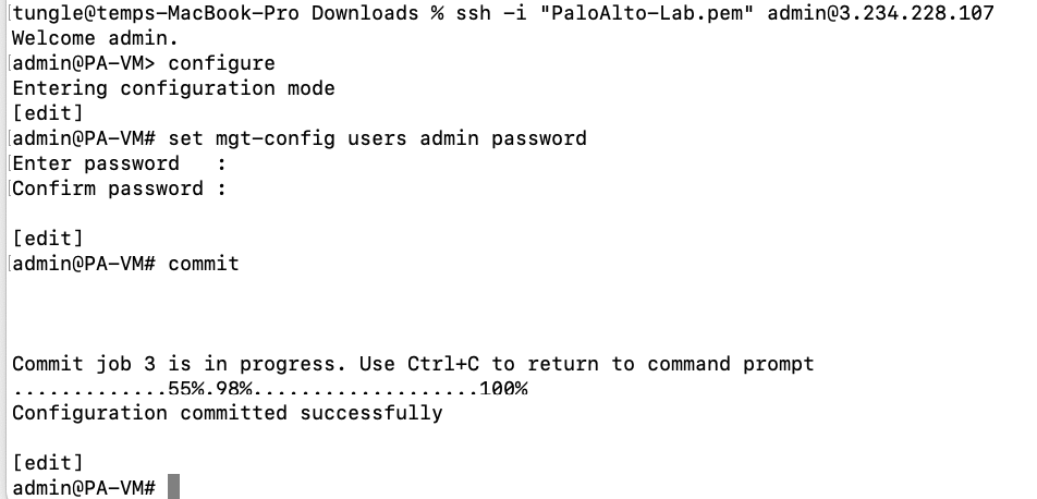
Change password of user admin.
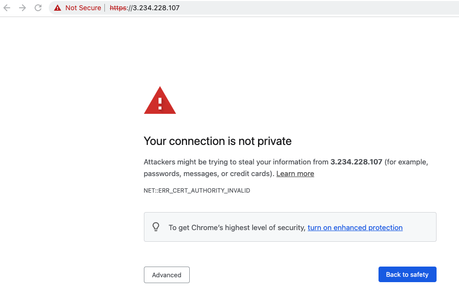
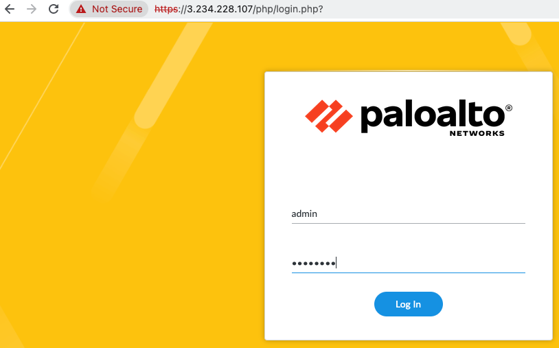
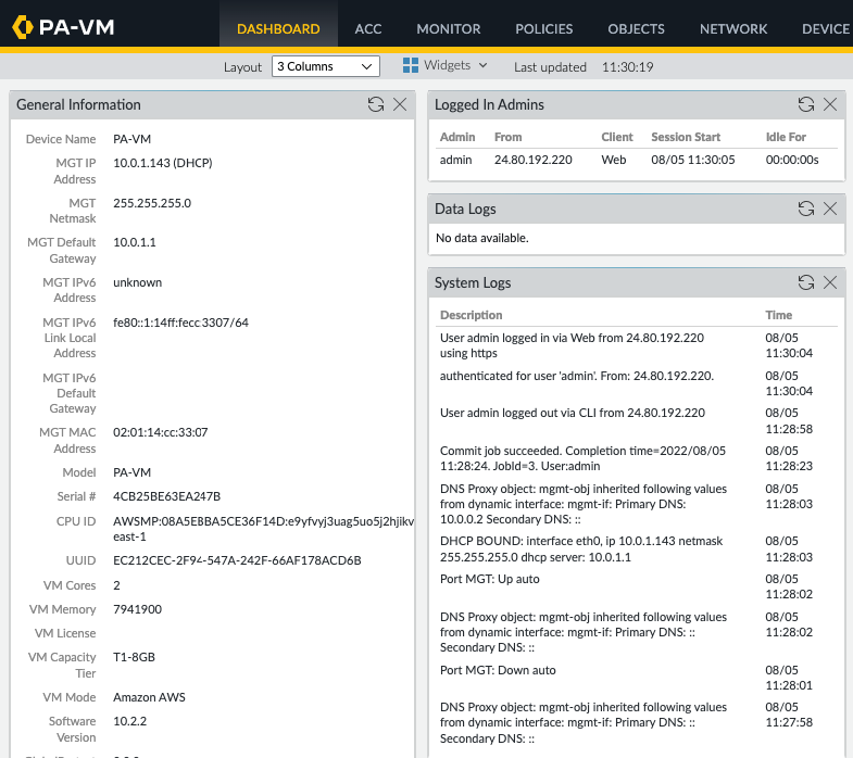
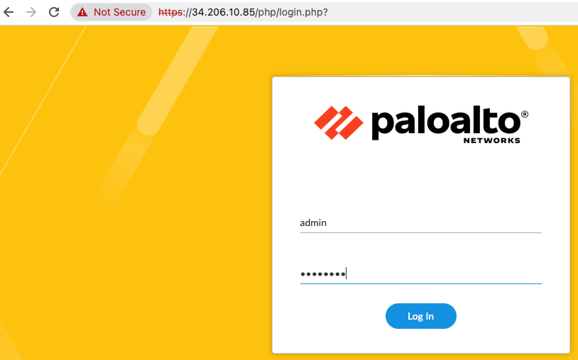
Log into PA via a web browser.
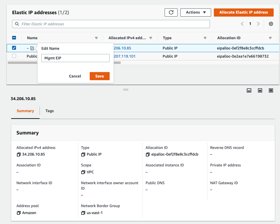
Back to EC2 – EIP. Assign a permanent Elastic IP address (IP address does not change when the instance is stopped) for Management interface to and rename “-” to Mgmt EIP.
Access the PA via Elastic IP address.
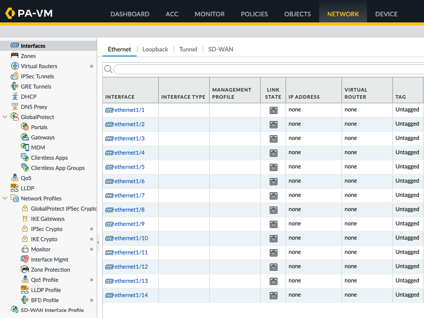
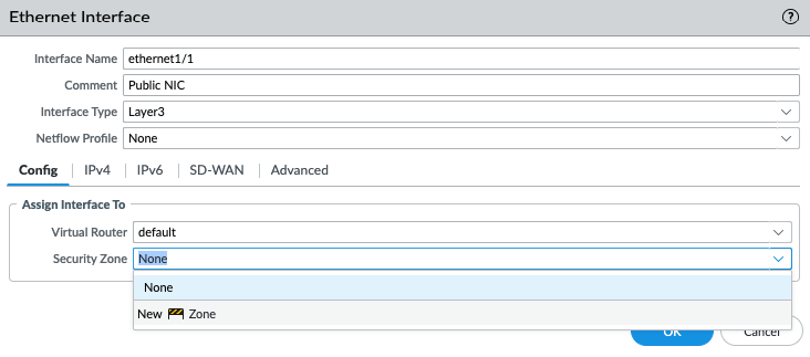
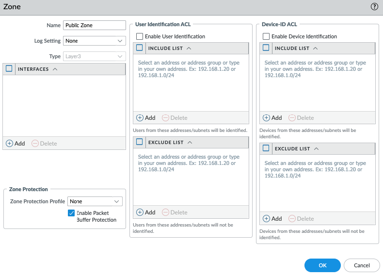
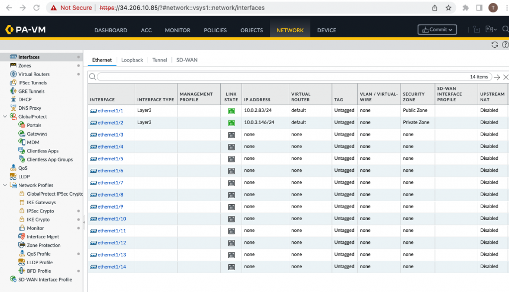
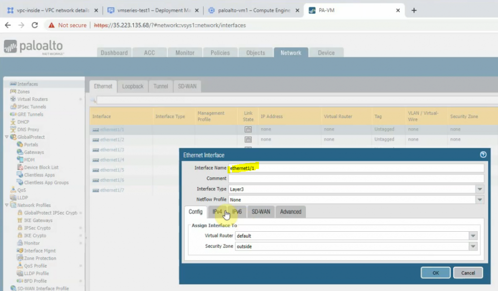
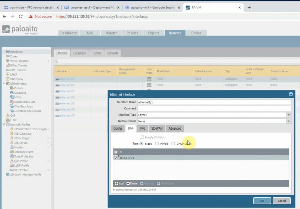
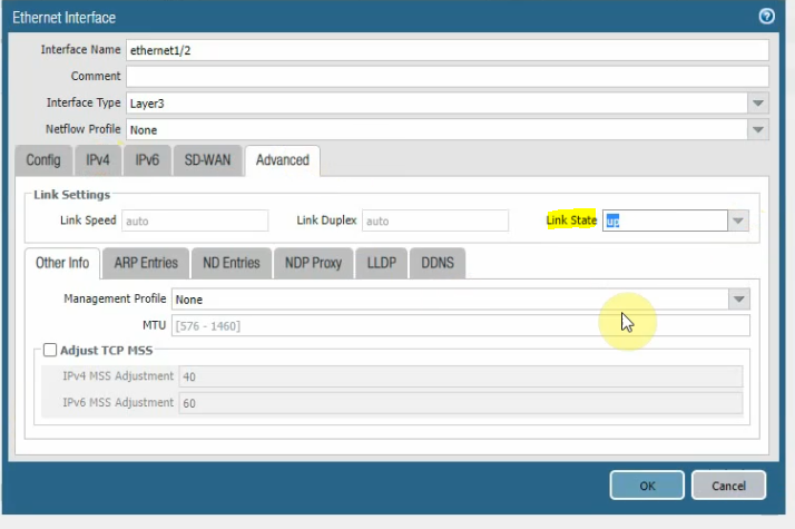
Configure the Public interface (e1/1) of PA.
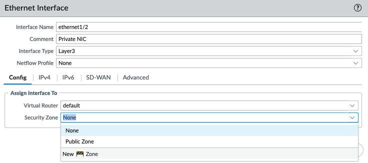
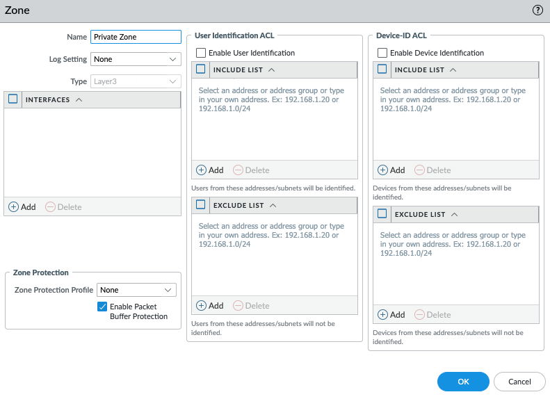
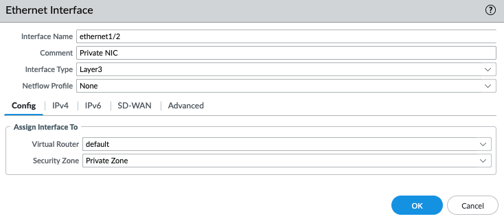
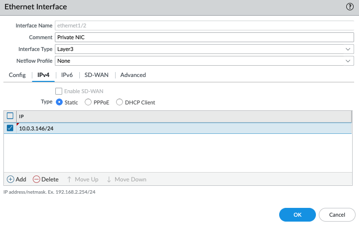
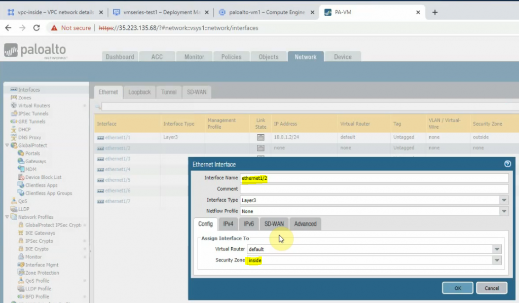
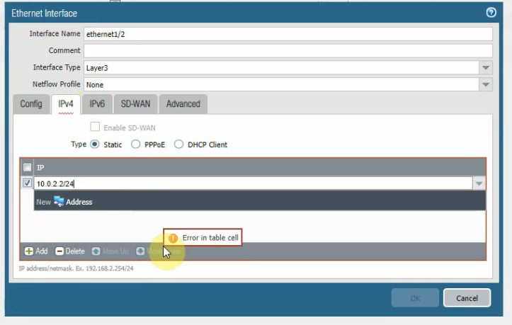
Configure the Private interface (e1/2) of PA.
Commit the settings.
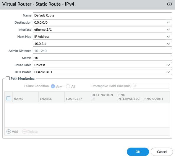
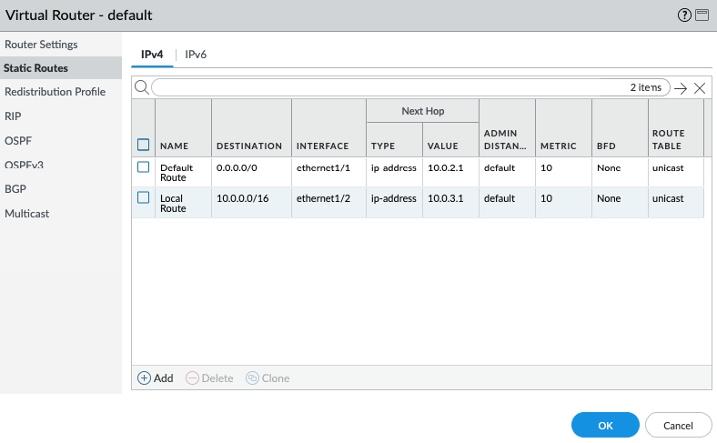
Create a default route via the Public interface.
Create a local route to allow traffic from the PVC network via the Private interface.
Back to VPC, edit routes in “Private route”.
Add a default route via “Private network”.
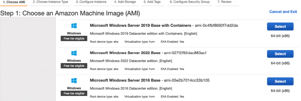
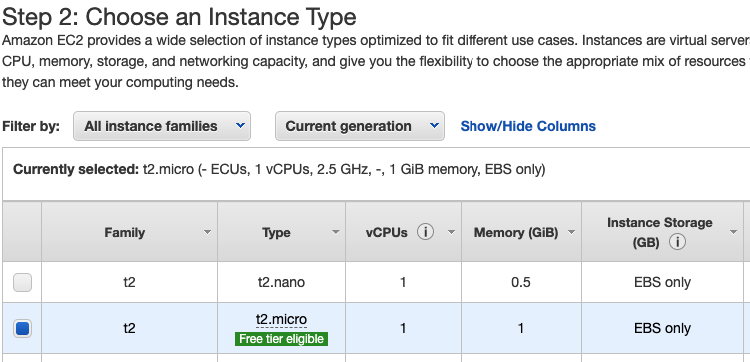
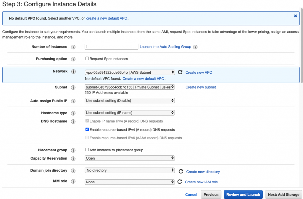
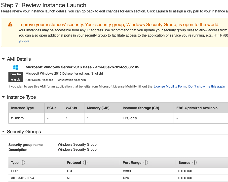
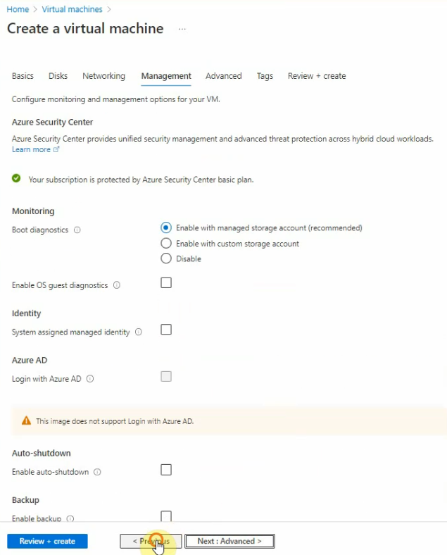
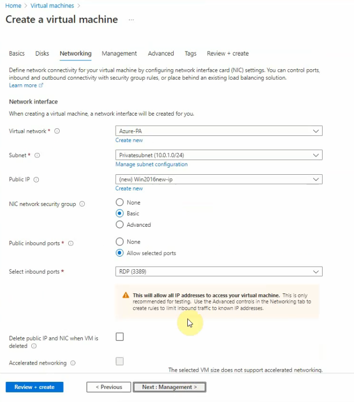
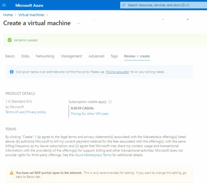
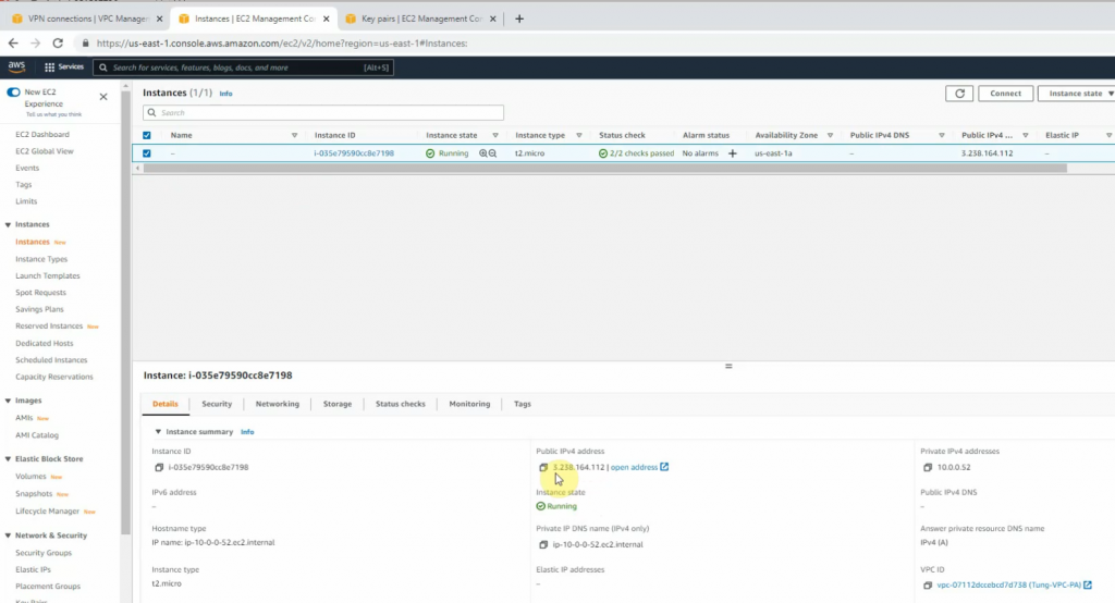
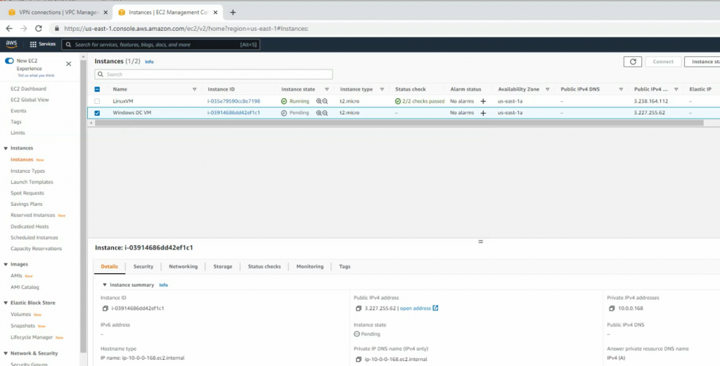
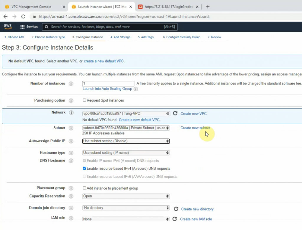
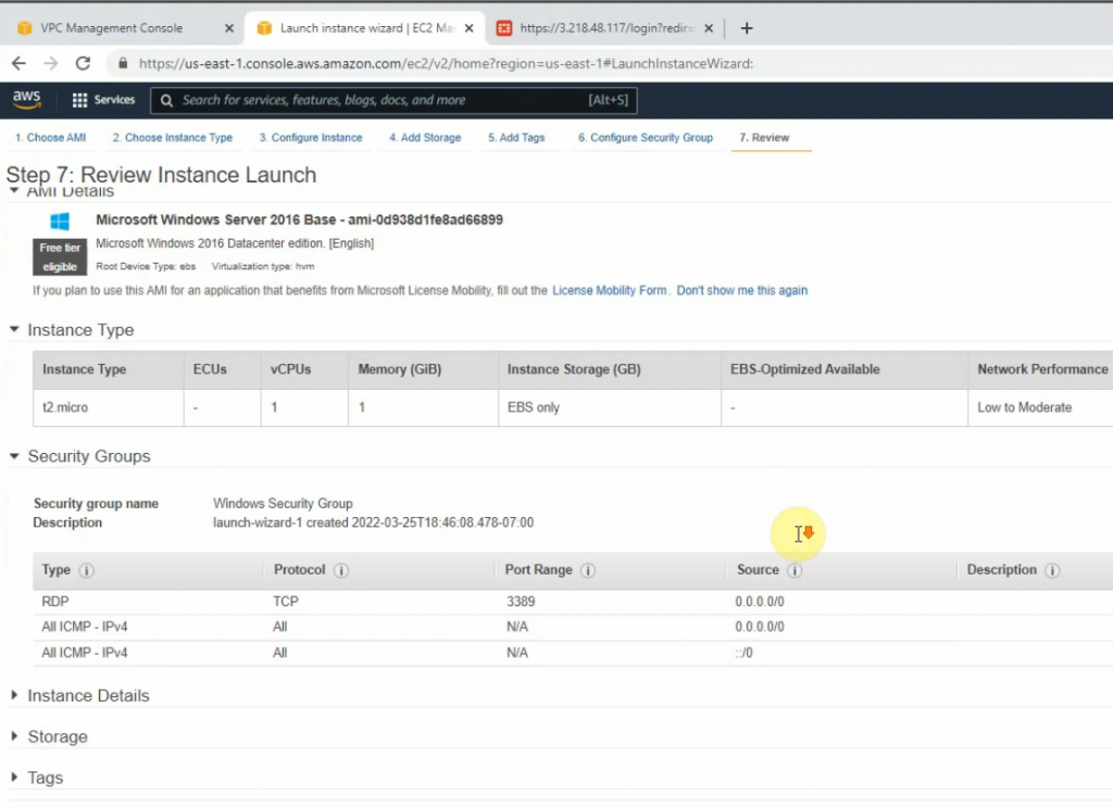
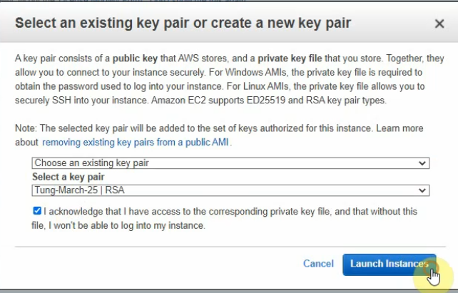
Back to EC2 – instances, create a new Windows VM in the Private network.
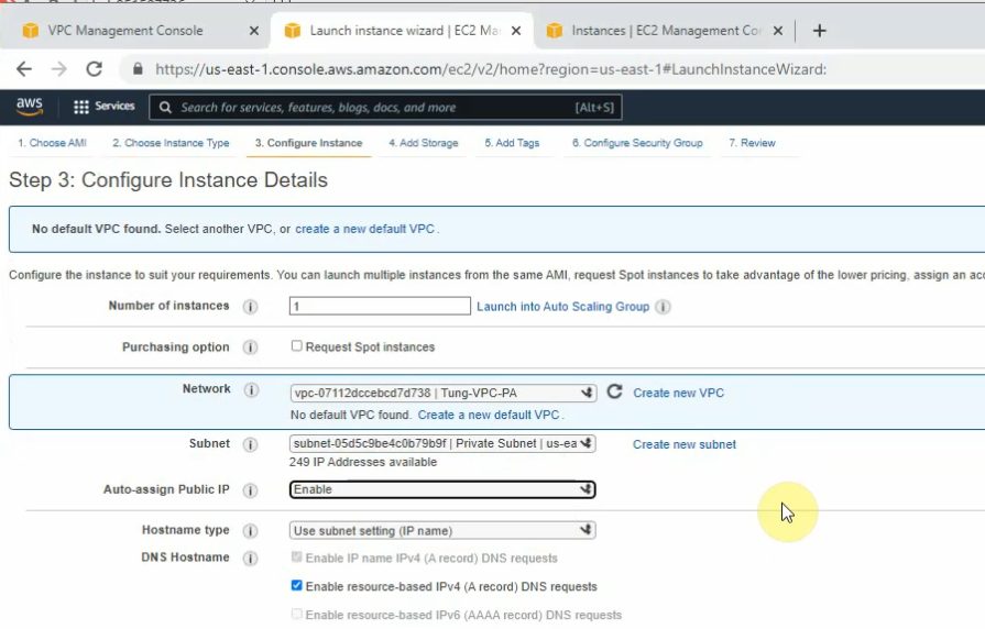
Select “Private Subnet” in Subnet setting and Disable in “Auto-assign Public IP”.
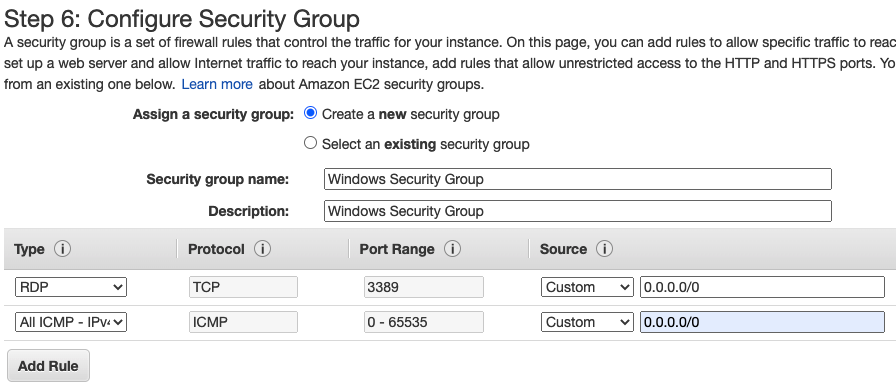
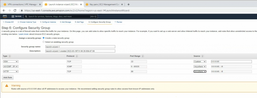
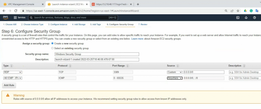
Add the ICMP line to allow ICMP traffic in this Security Group.
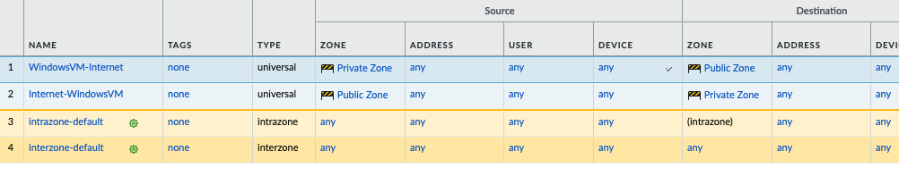
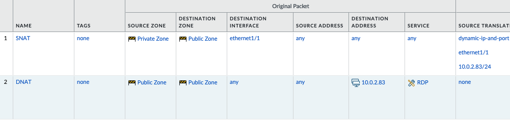
Move to PA, create 2 security polices to allow traffic from Private Zone to Public Zone and vice versa.
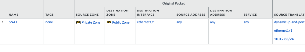
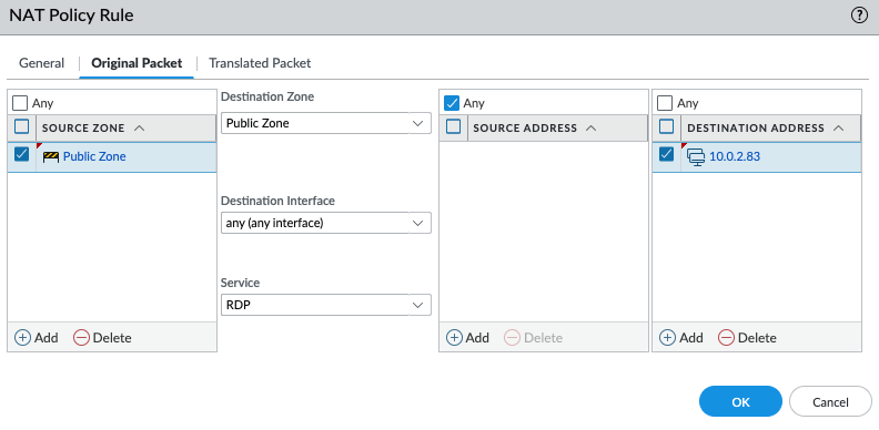
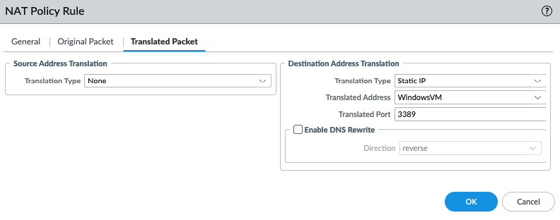
Create a SNAT and DNAT to allow traffic from Windows VM to the Internet and RDP traffic from Internet to Windows VM in Private subnet.
SNAT.
DNAT.
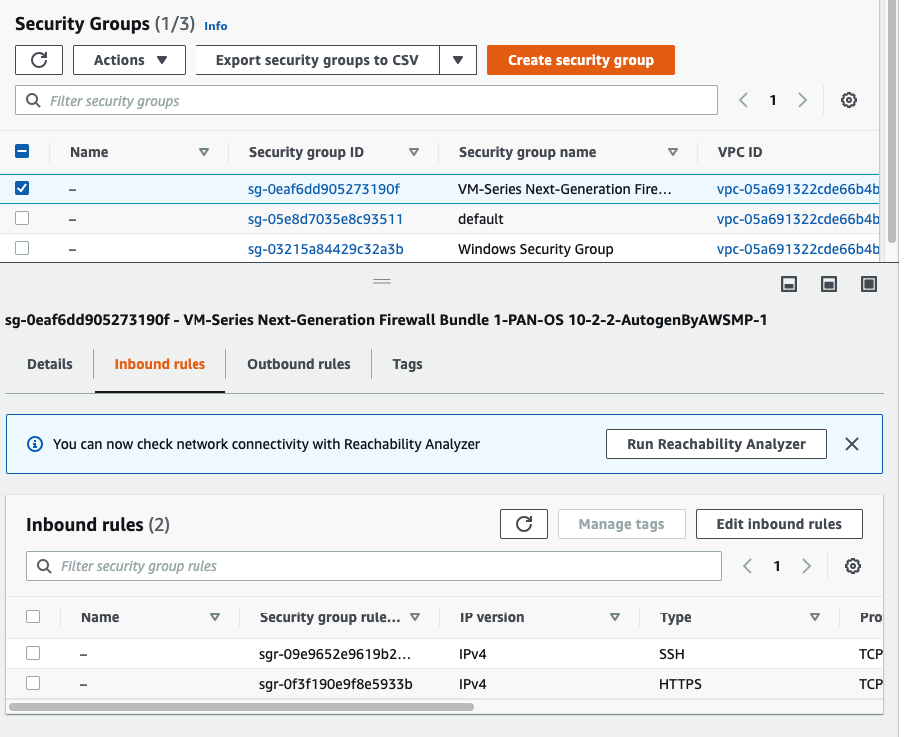
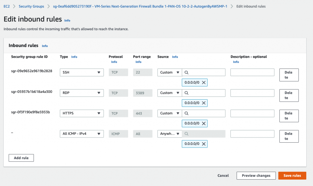
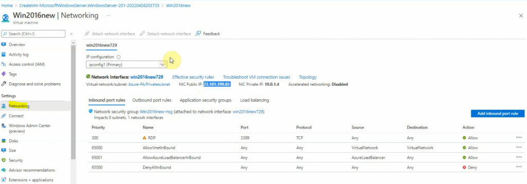
Back to AWS – EC2 – Security Group, add RDP and ICMP into the following Security Group.
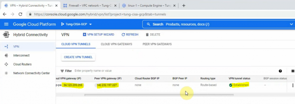
I have set up the first part for Palo Alto on GCP (https://tungle.ca/?p=3760). Now, I go to set up the VPN site-to-site between Palo Alto on-prem and Palo Alto on GCP.
On Palo Alto on-prem.
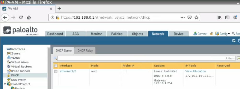
Setup DHCP service on the e1/2 interface.
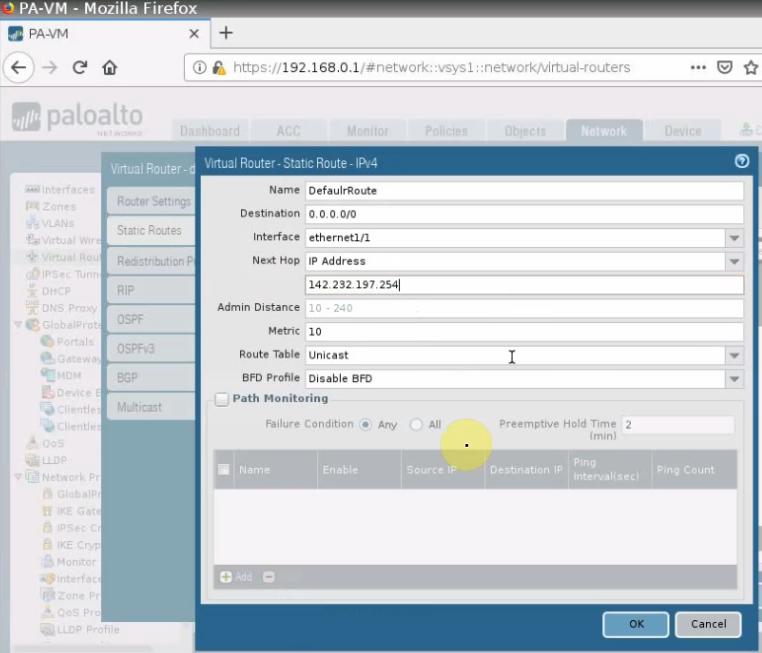
Set the default route on Palo Alto.
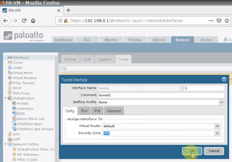
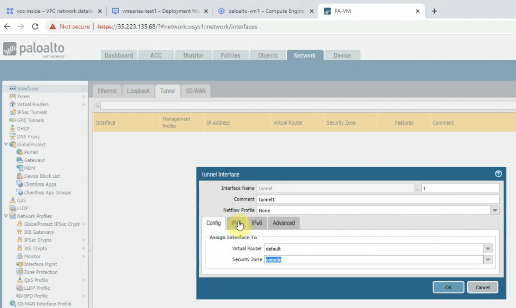
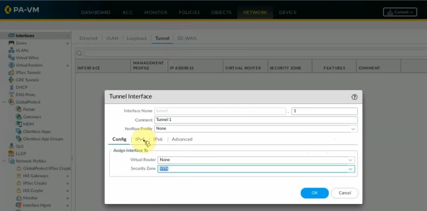
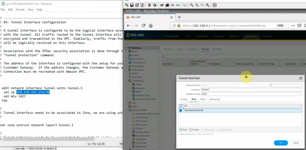
Create a tunnel 1 on Palo Alto.
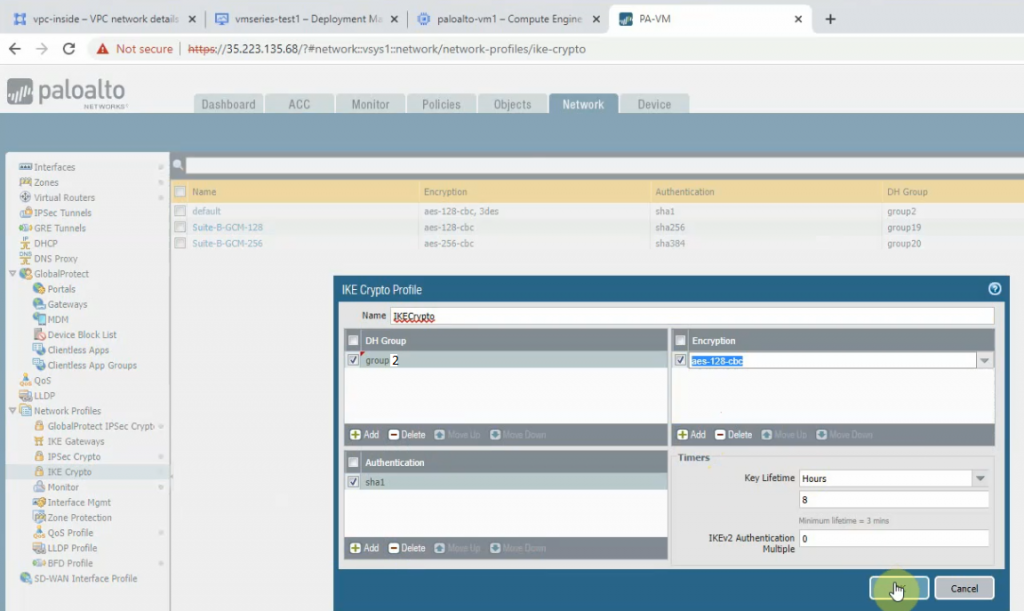
Create an IKECrypto.
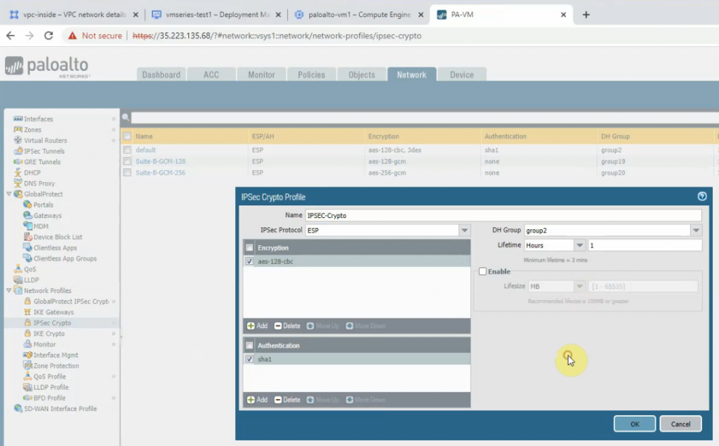
Create an IPSECCrypto.
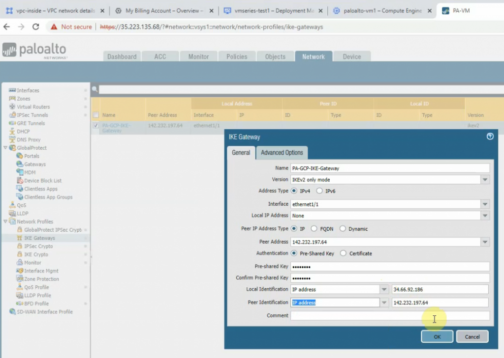
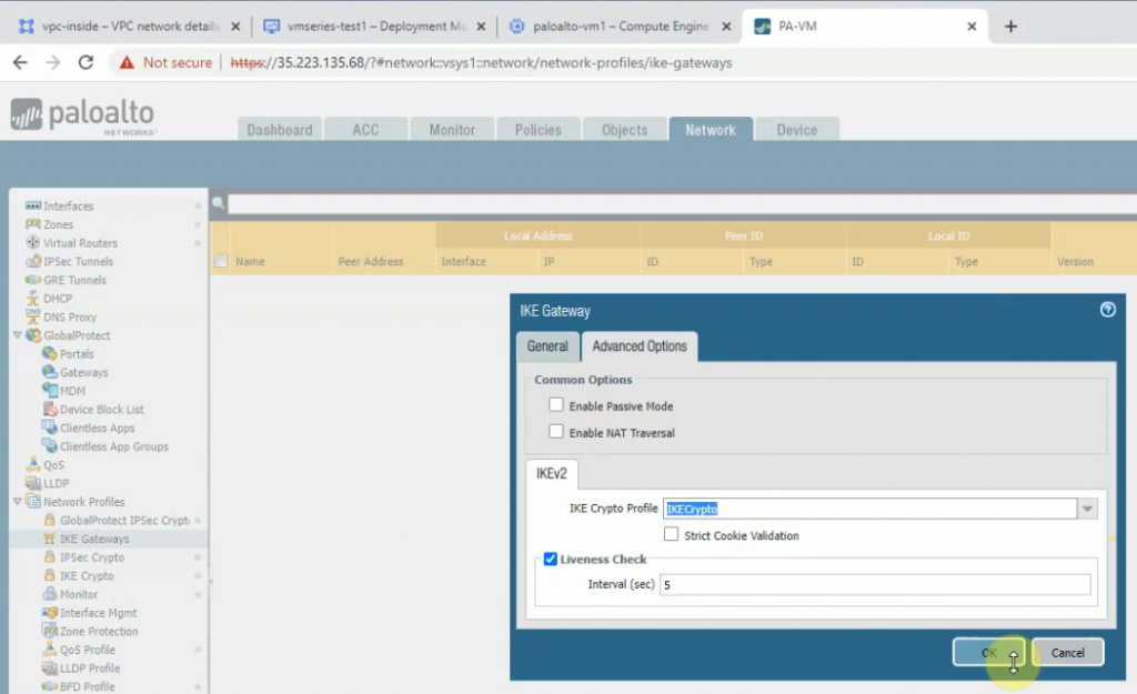
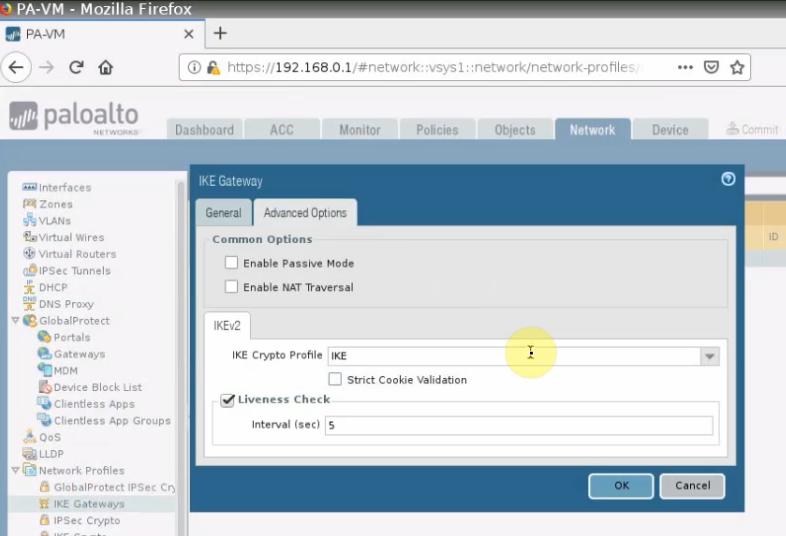
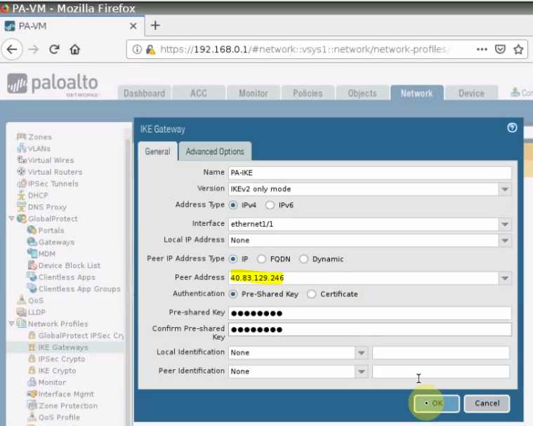
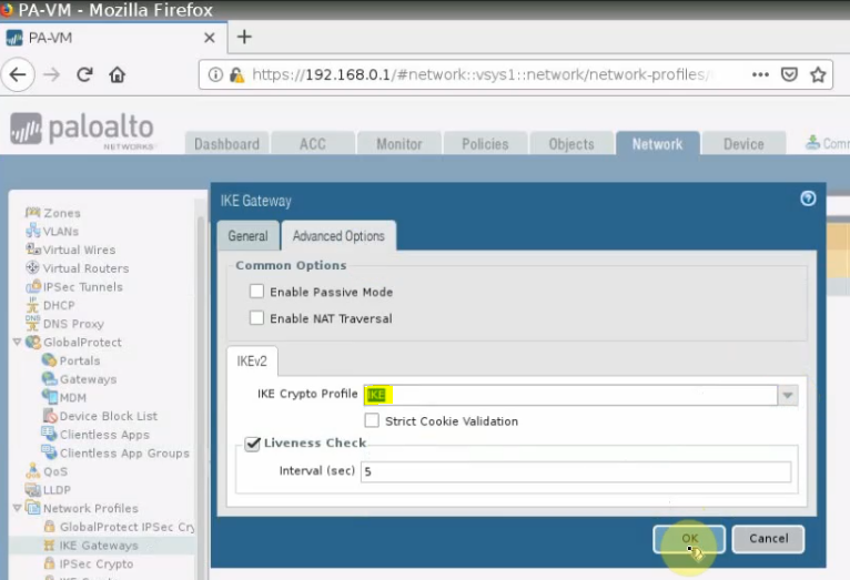
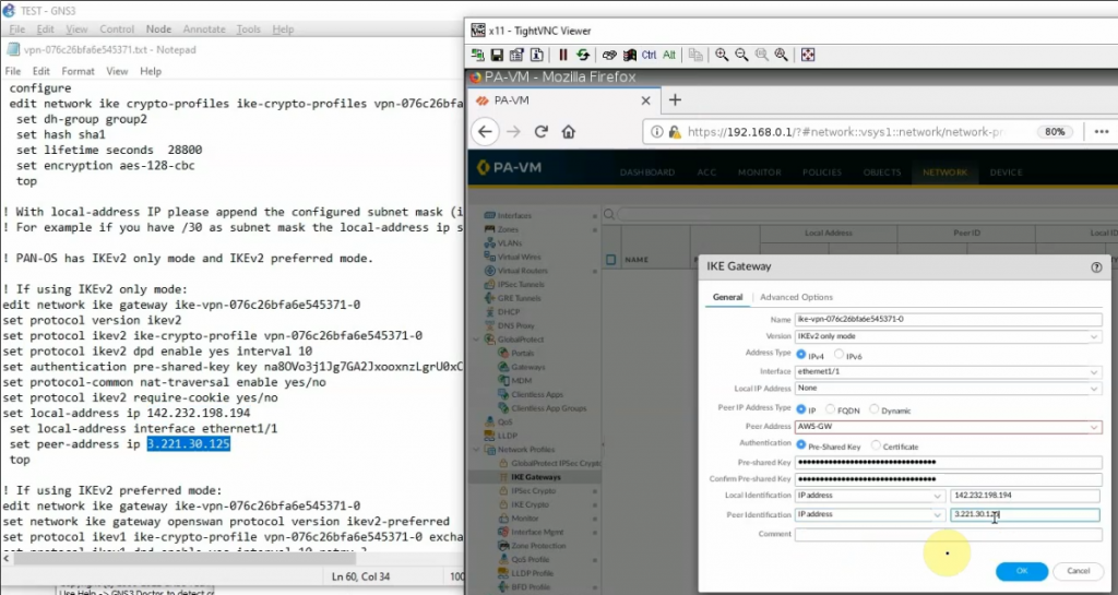
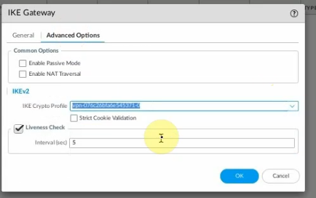
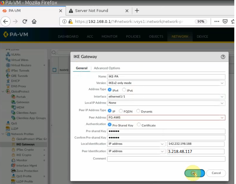
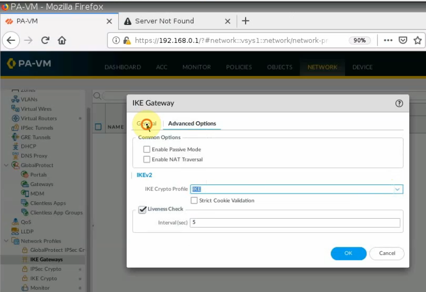
Create an IKEGateway.
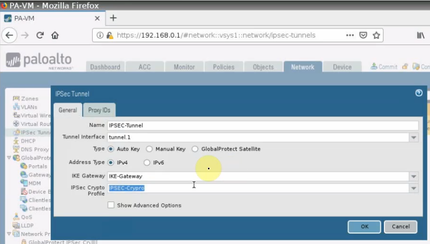
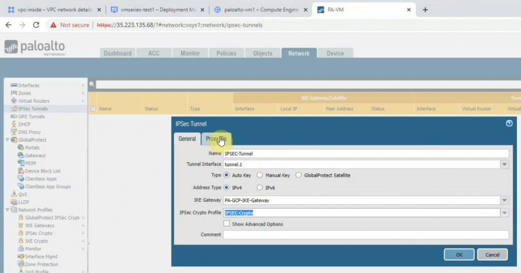
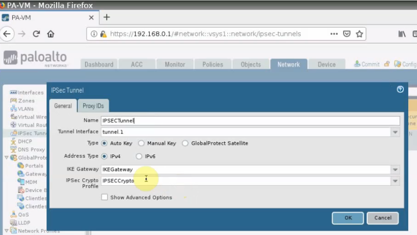
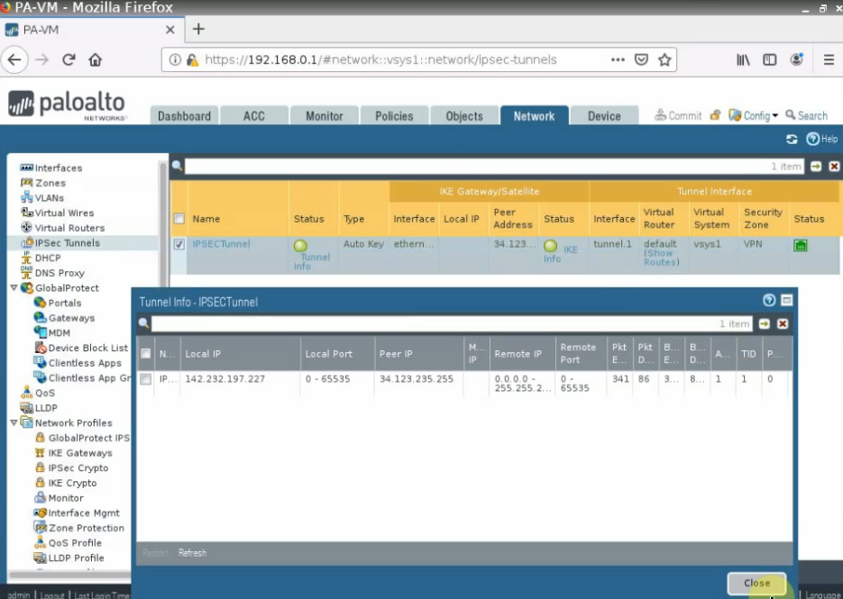
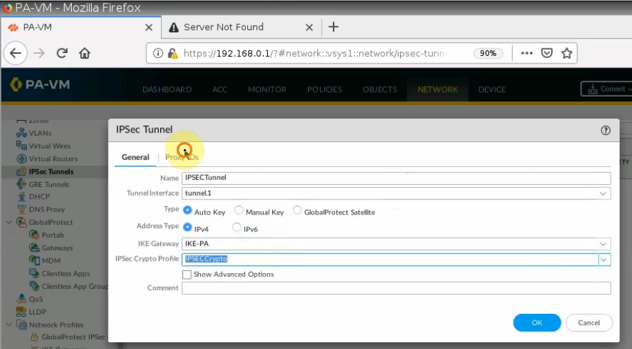
Create an IPSECTunnel.
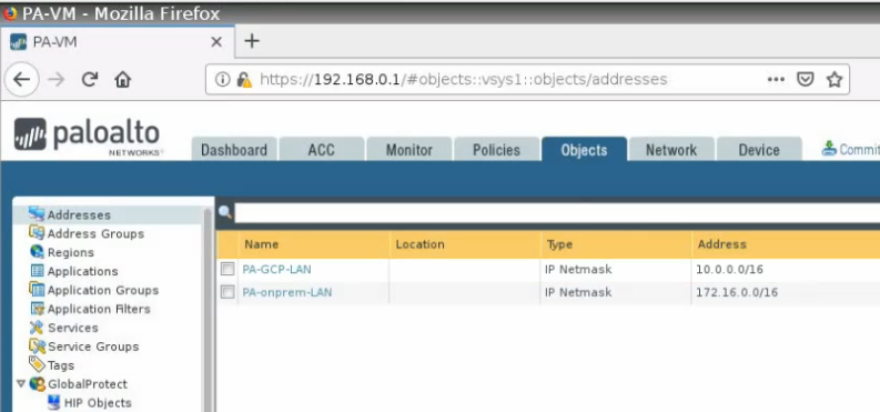
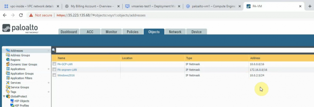
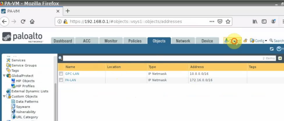
Create network objects for LAN subnets of Palo Alto on-prem and on GCP.
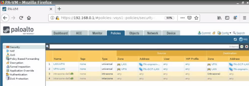
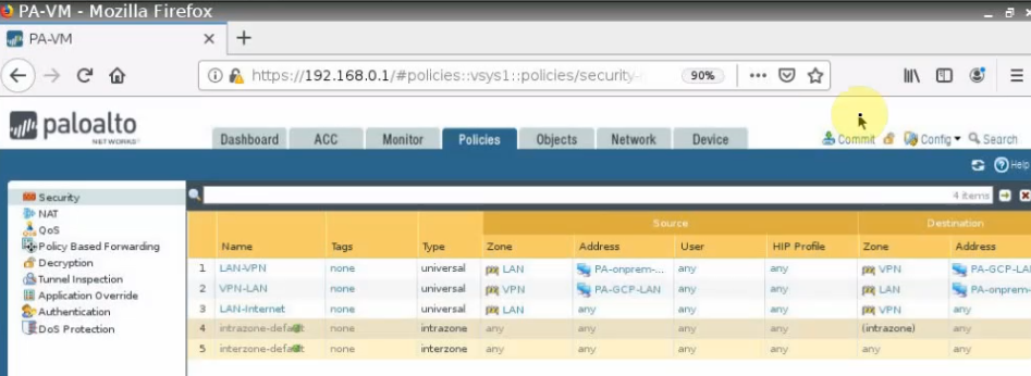
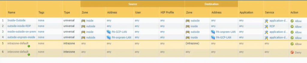
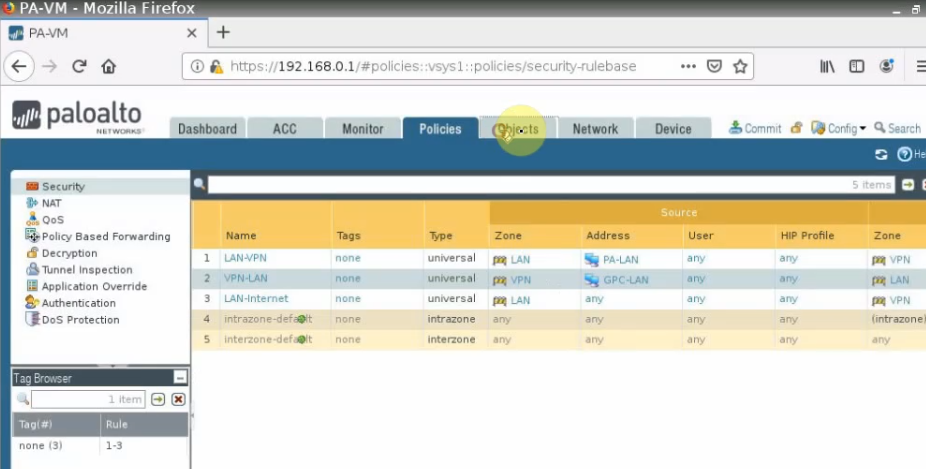
Create both security policies to allow traffic from LAN subnets on Palo Alto – GCP to LAN subnets on Palo Alto on-prem and vice versa.
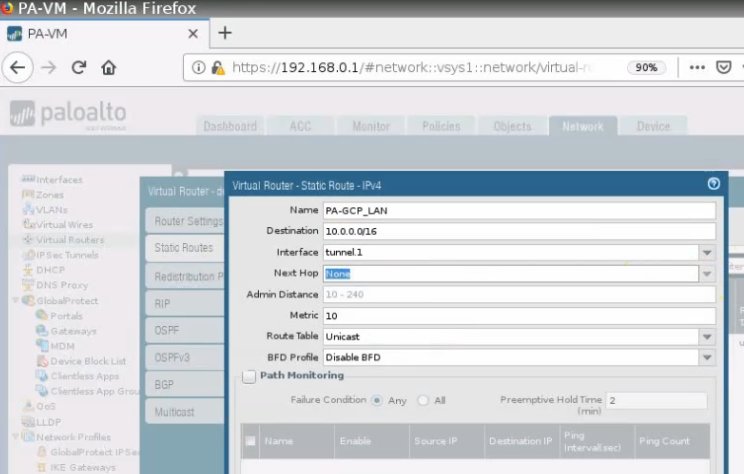
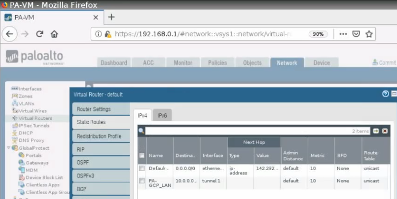
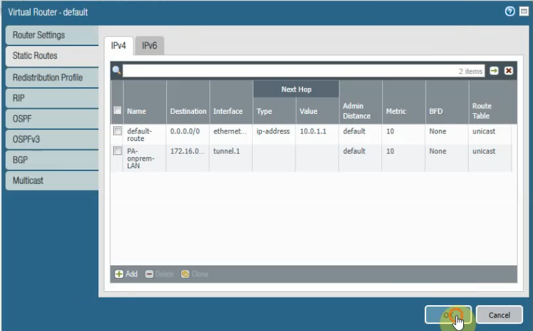
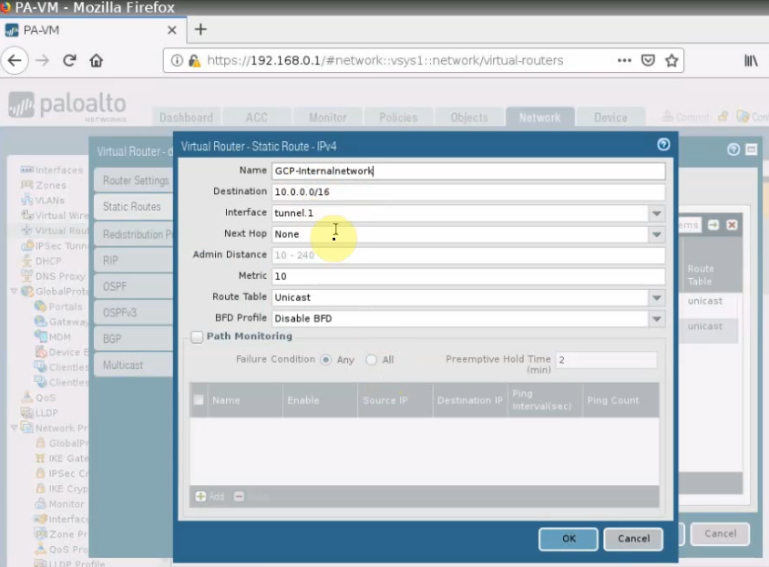
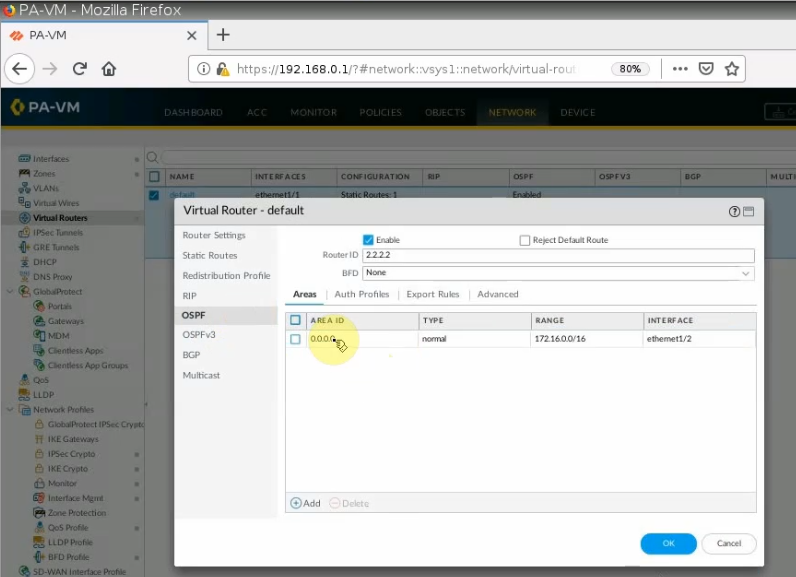
Create a static route to allow traffic from LAN subnets of Palo Alto on-prem to LAN subnets of Palo Alto on the cloud.
Create SNAT to allow the local network to access the Internet.
Create another access rule to allow traffic from the LAN network to access the Internet.
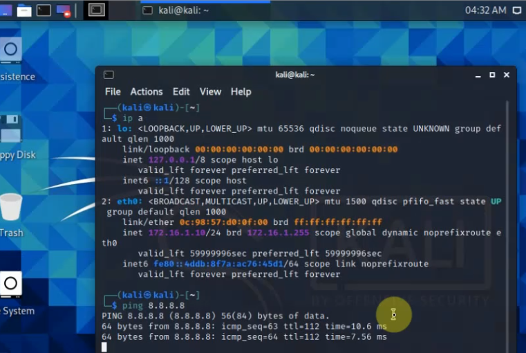
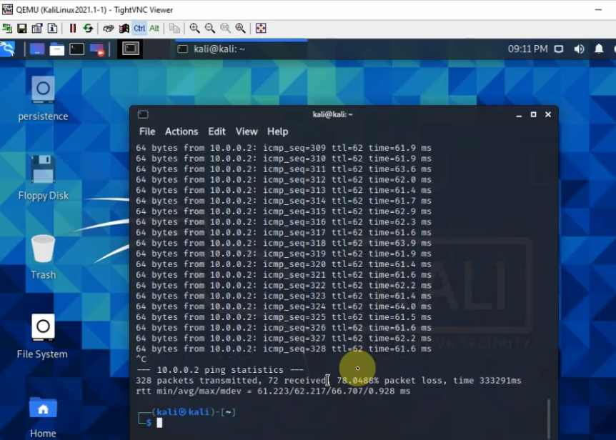
The Kali machine on the LAN network is able to access the Internet.
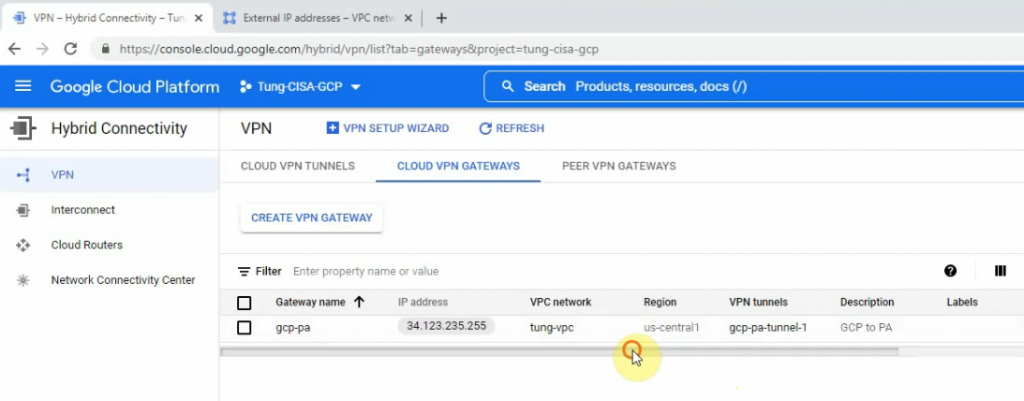
Back to Palo Alto on GCP.
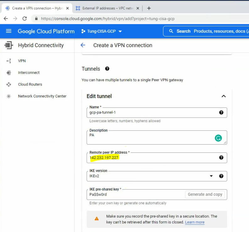
Create a tunnel 1 on Palo Alto.
Create an IKECrypto.
Create an IPSECCrypto.
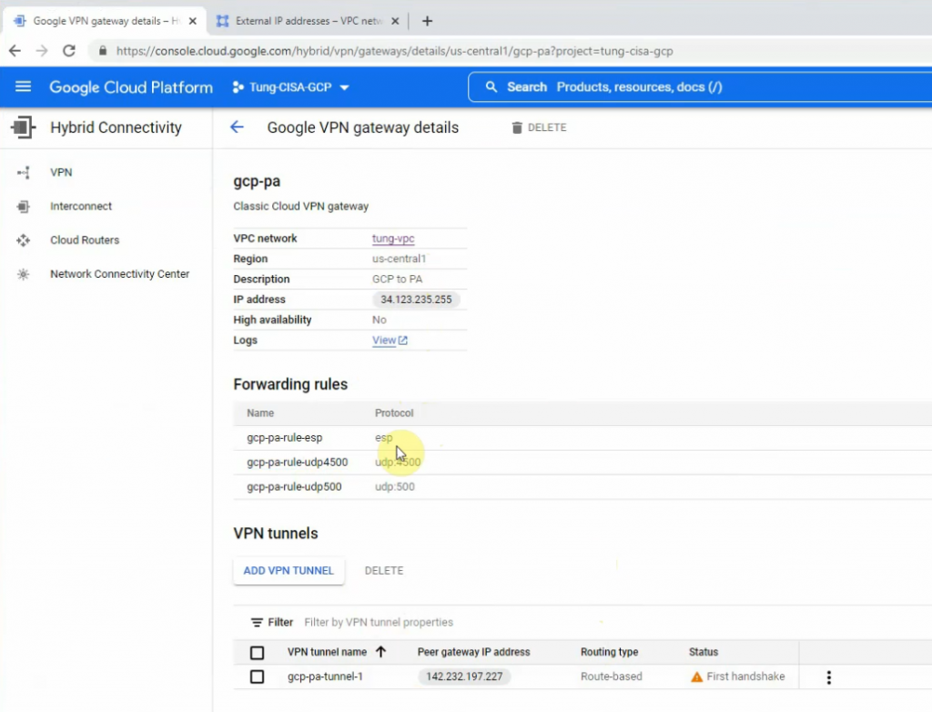
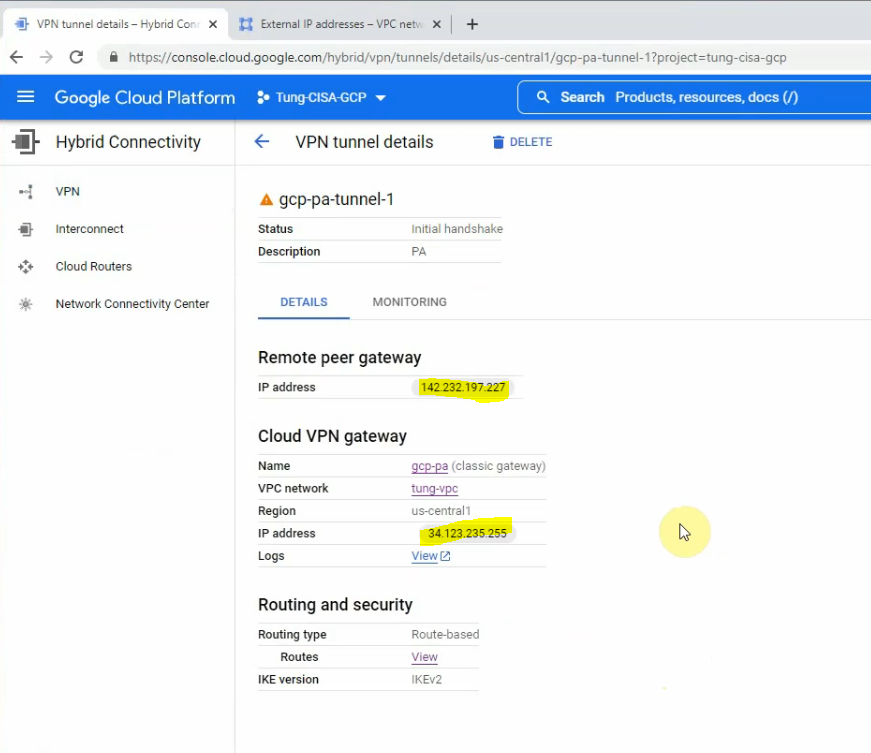
Create an IKEGateway.
Create an IPSEC tunnel.
Create network objects for LAN subnets for Palo Alto on-prem and on the cloud.
Create both security policies to allow traffic from LAN subnets on Palo Alto on GCP to LAN subnets on Palo Alto on-prem and vice versa.
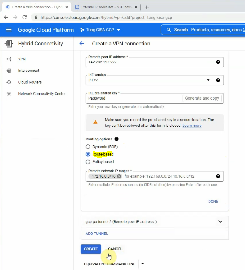
Create a static route to allow traffic from LAN subnets of Palo Alto on the cloud to LAN subnets of Palo Alto on-prem.
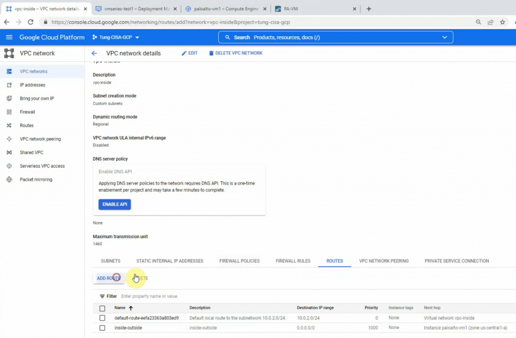
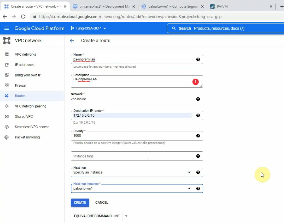
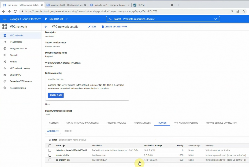
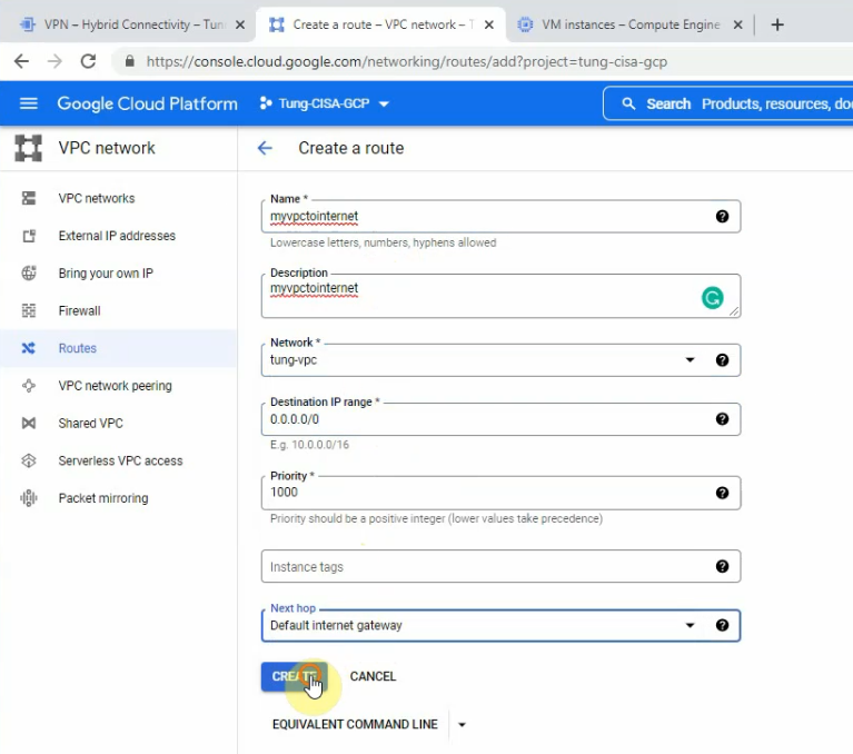
Go to the vpc-inside network, and create “Add route” to add a new route to LAN subnets of Palo Alto on-prem.
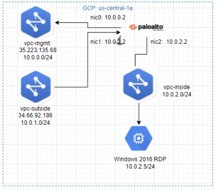
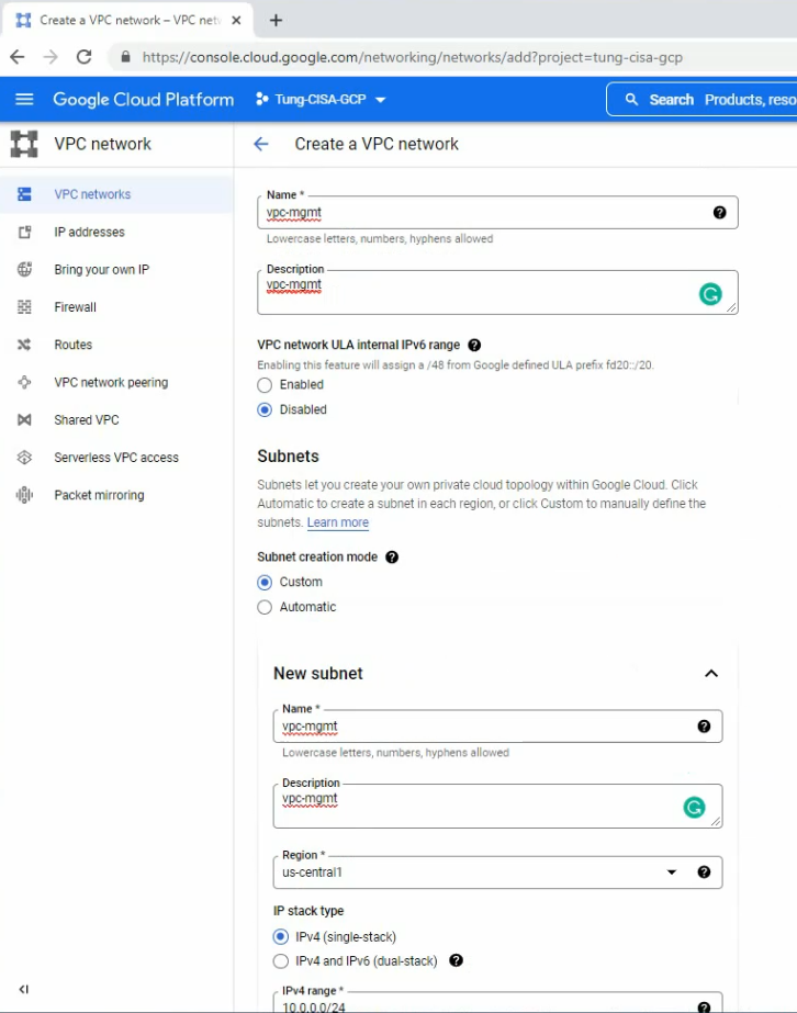
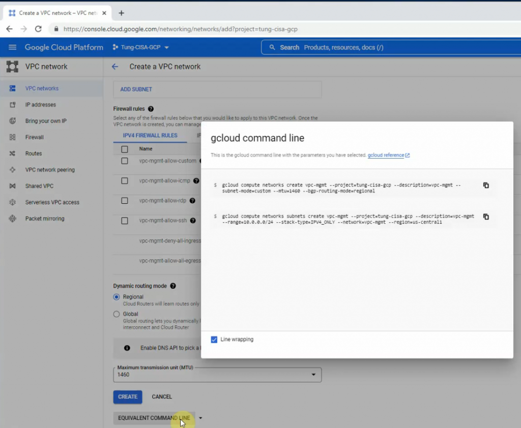
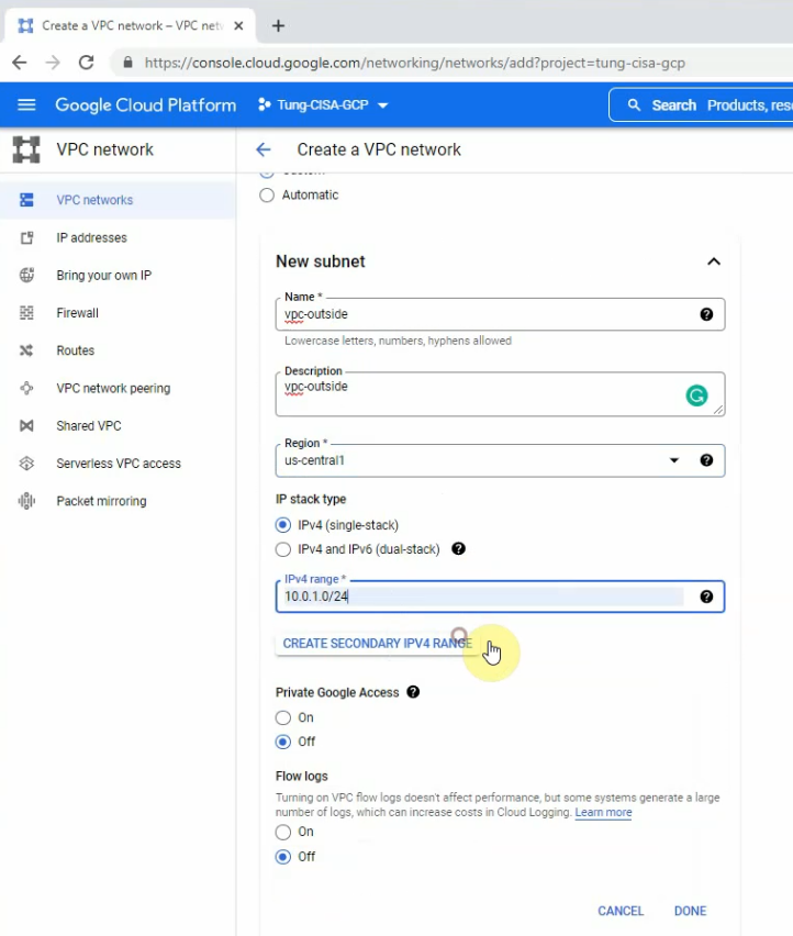
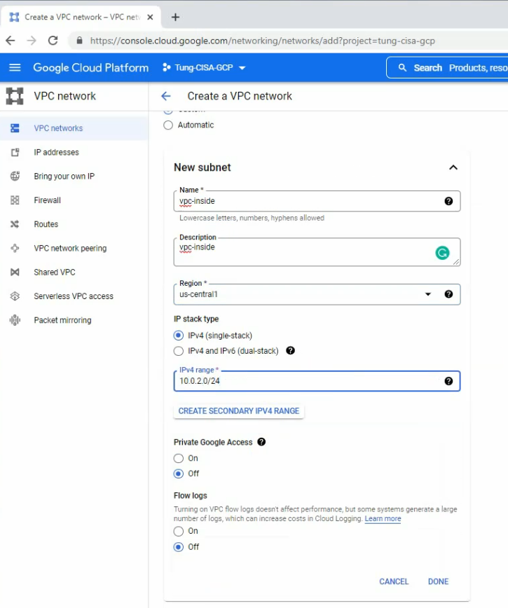
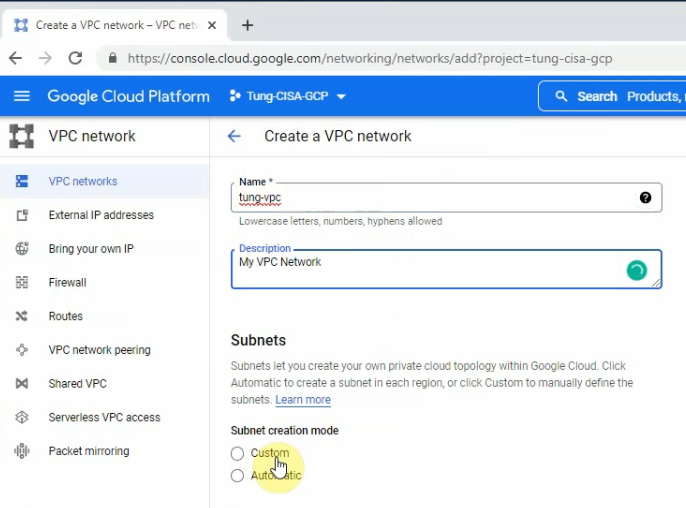
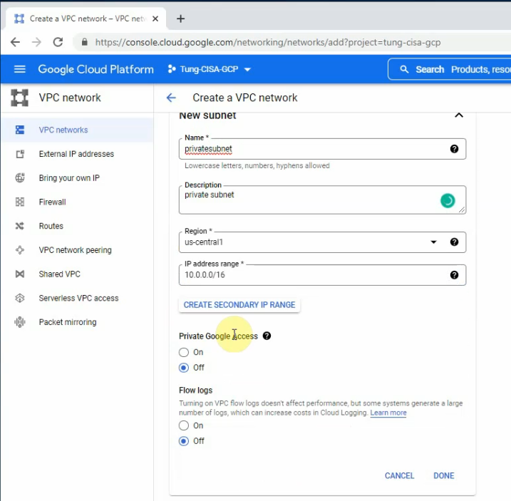
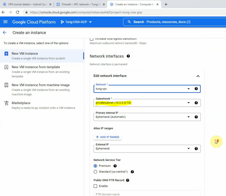
Create 3 vpc networks: vpc-mgmt (10.0.0.0/24), vpc-outside (10.0.1.0/24), and vpc-inside (10.0.2.0/24) on GCP.
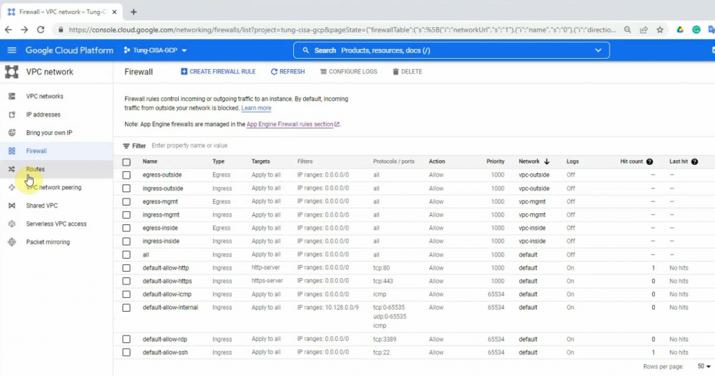
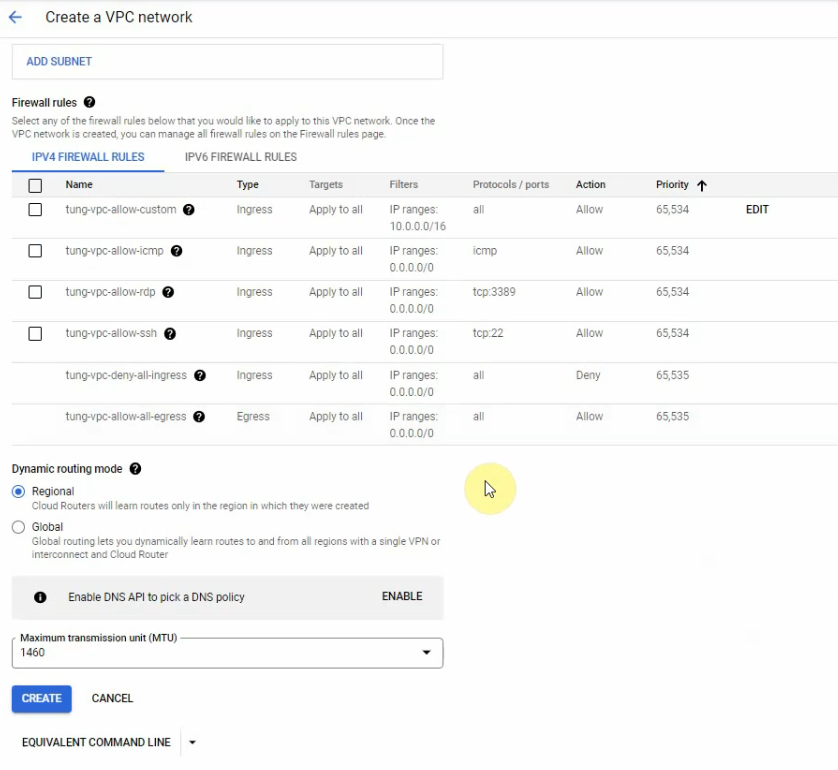
Create ingress/egress Firewall rules on the vpc networks.
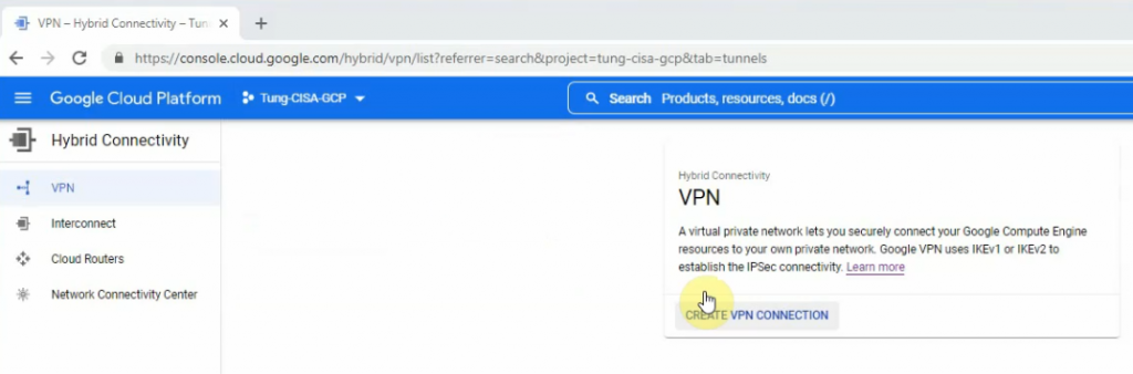
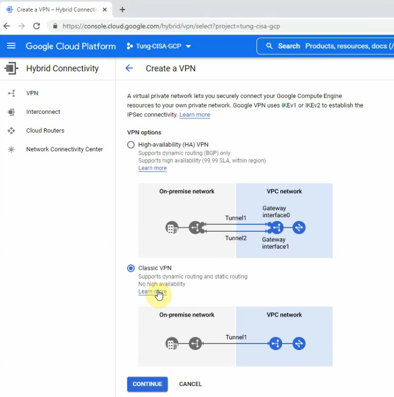
Launch Palo Alto instance on GCP.
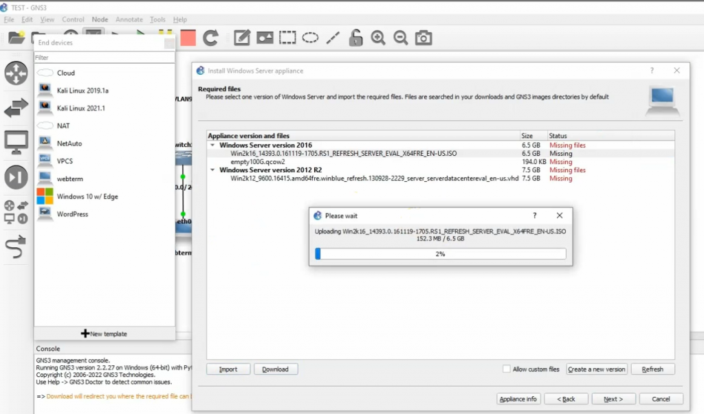
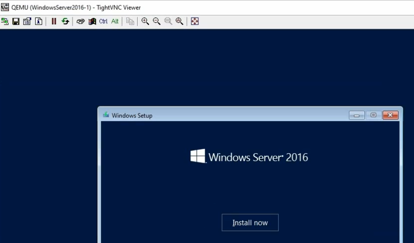
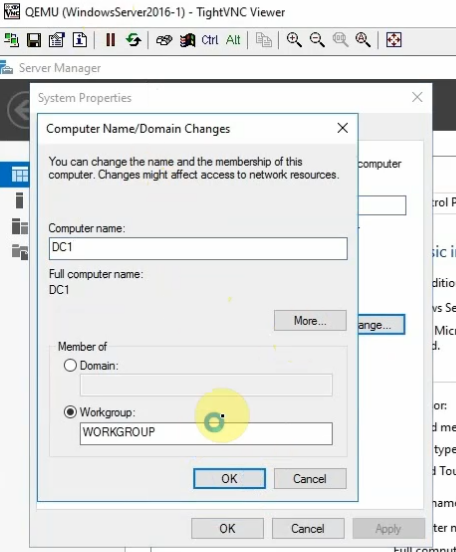
Launch Windows 2016 instance on the inside network.
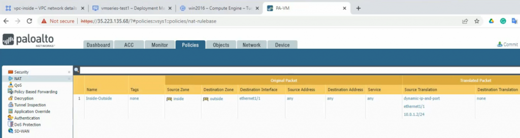
Create a default route, security rules, SNAT, and DNAT for RDP traffic from the Internet to Windows 2016 instance via Palo Alto.
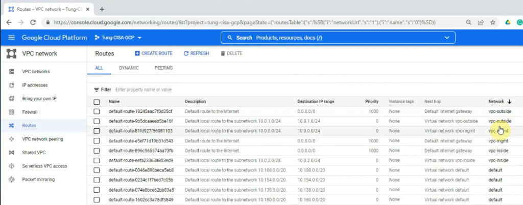
Modify the default route for the inside network to use the Palo Alto instance.
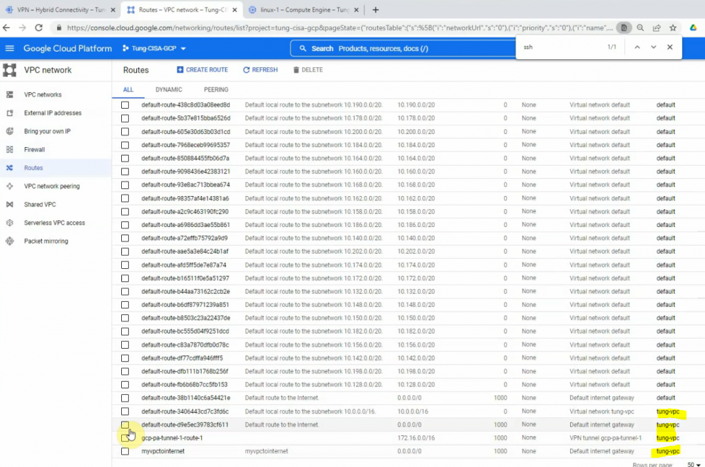
VPC Network – Route tables.
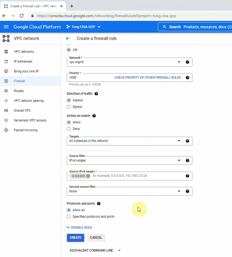
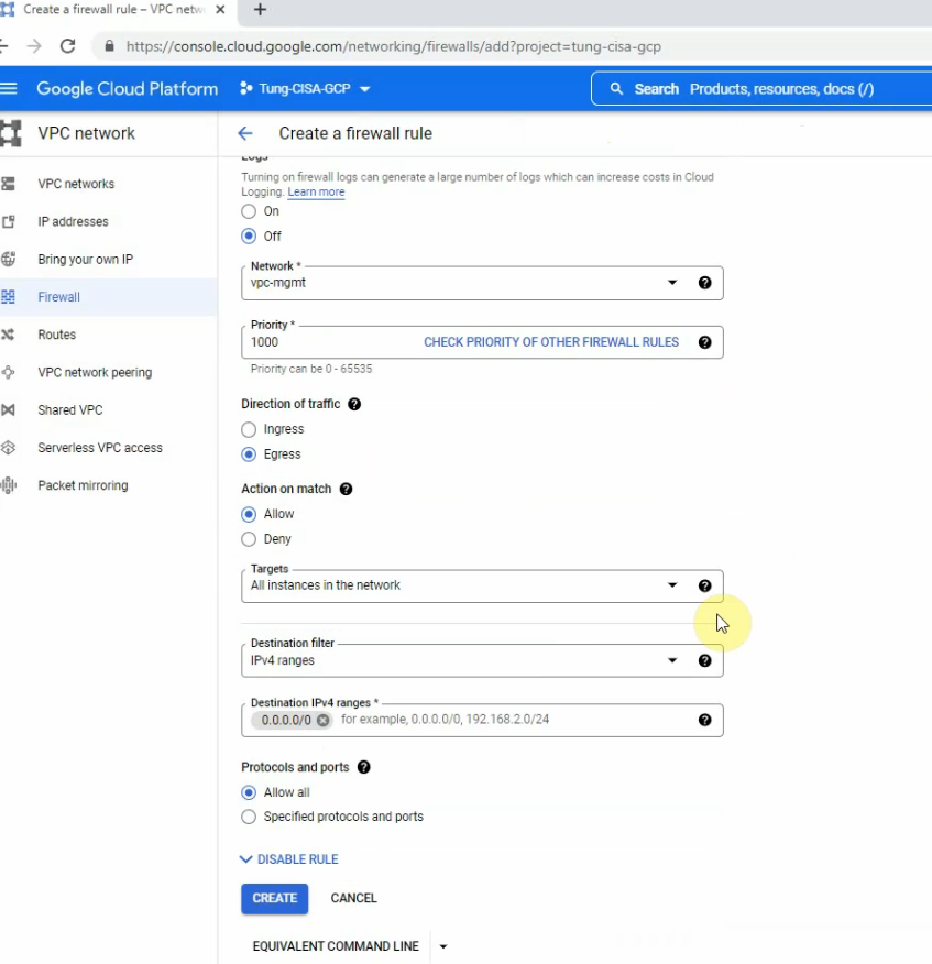
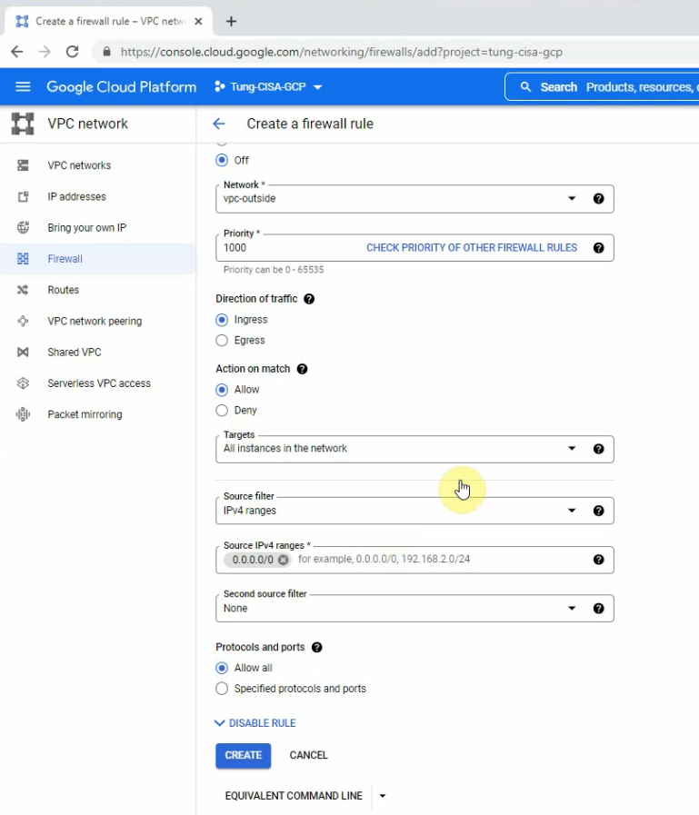
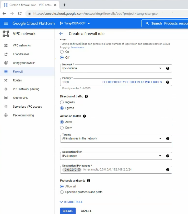
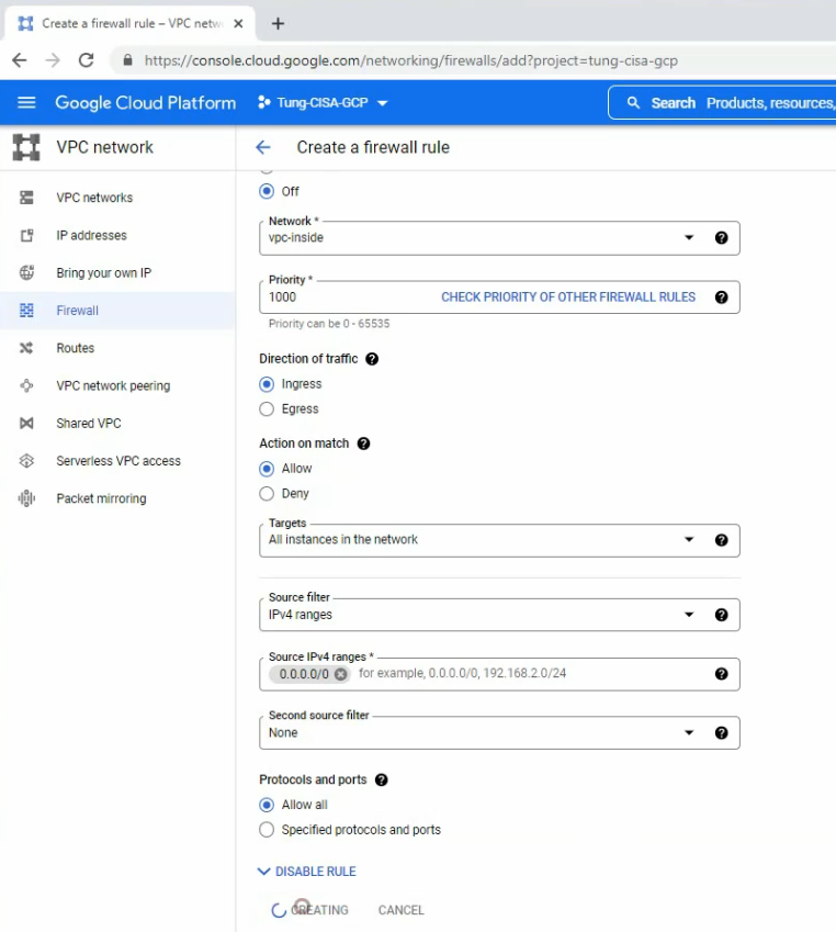
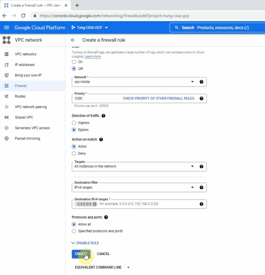
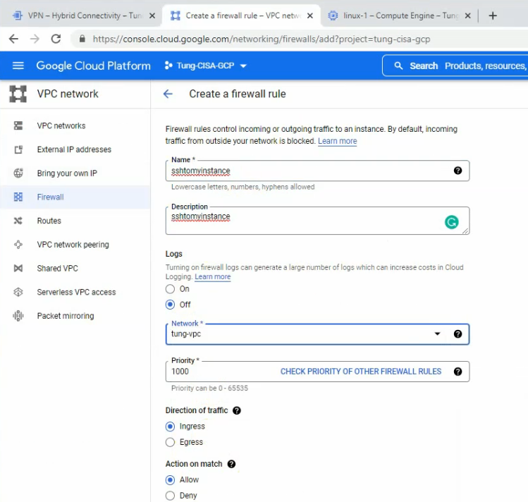
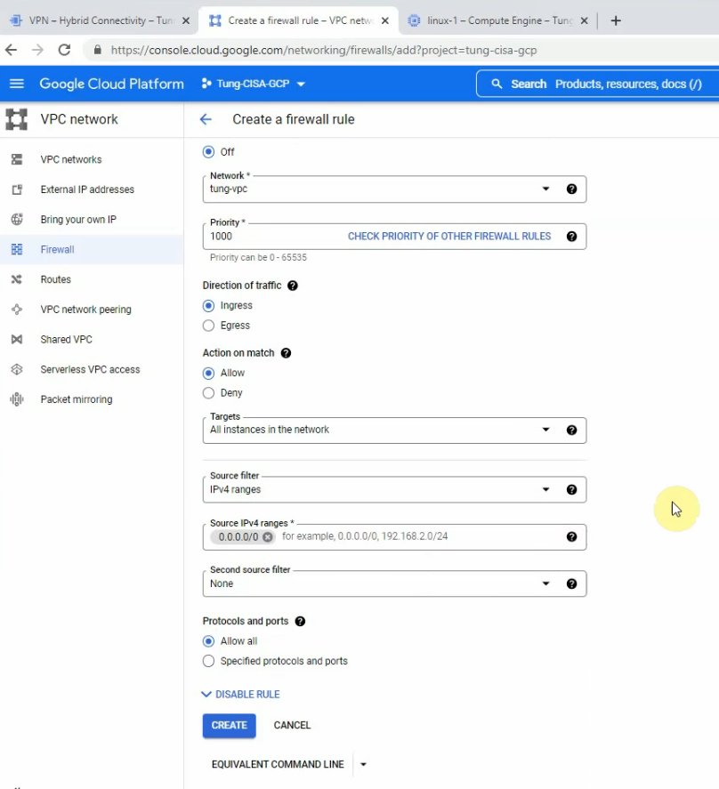
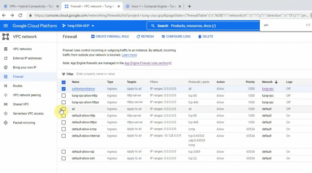
Go to VPC network – Firewall – Create a firewall rule for ingress/egress traffic from and to the network 0.0.0.0/0.
The ingress-mgmt rule.
The egress-mgmt rule.
The ingress-outside rule.
The egress-outside rule.
The ingress-inside rule.
The egress-inside rule.
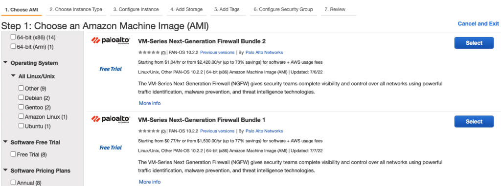
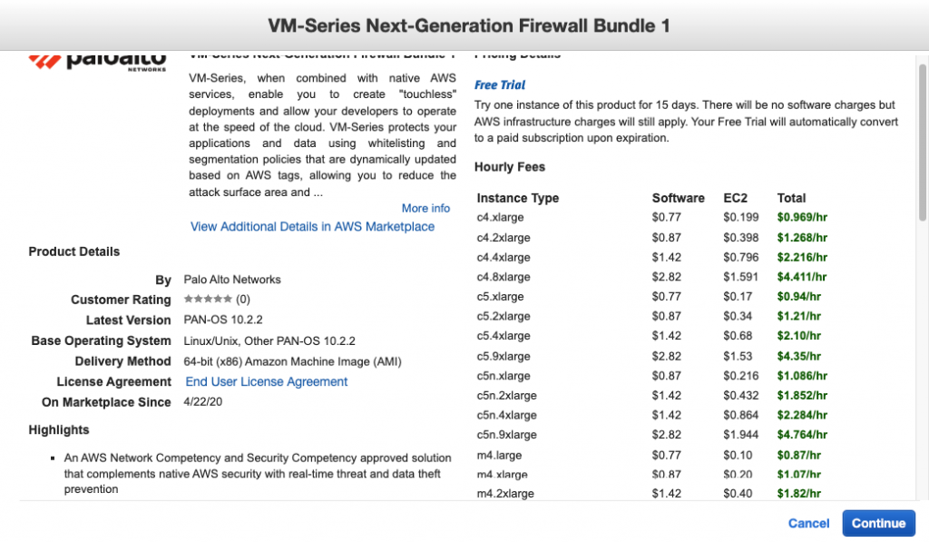
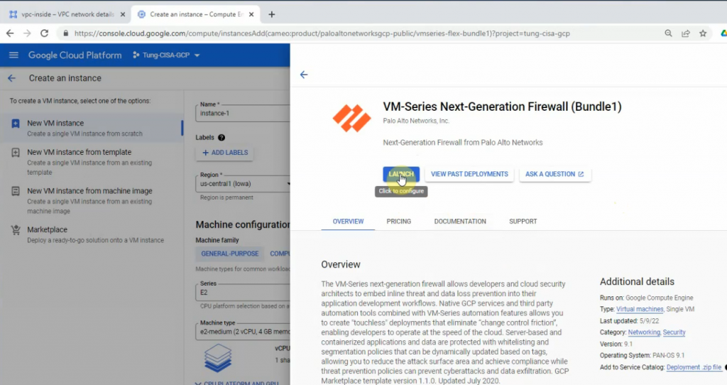
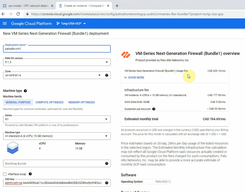
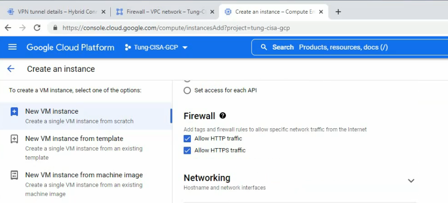
Go to Compute Engine – Create an instance – Marketplace – enter “Palo Alto” – select “VM-series Next-Generation Firewall (Bundle 1)” – click launch.
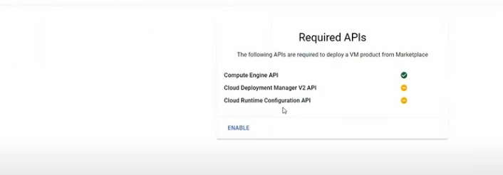
Click Enable on the Required APIs.
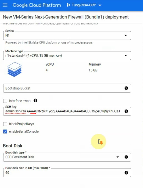
Back to create Palo Alto VM.
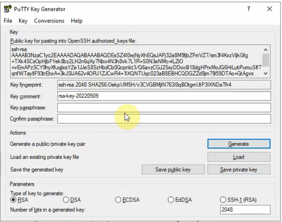
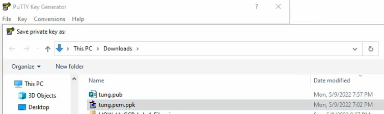
Using the puttygen to generate an SSH key pair. Click to save the public and private keys.
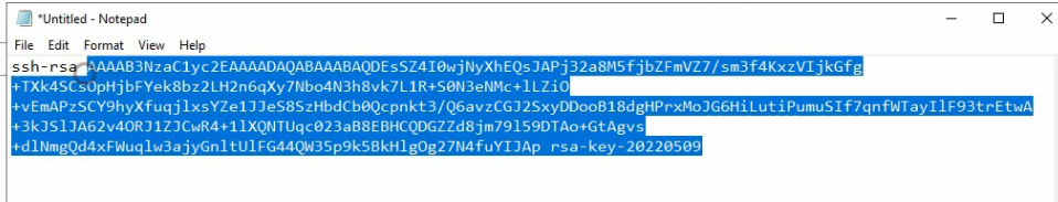
This is a public key that you need to submit when creating the Palo Alto VM on GCP.
Copy the key and pass it into the SSH key.
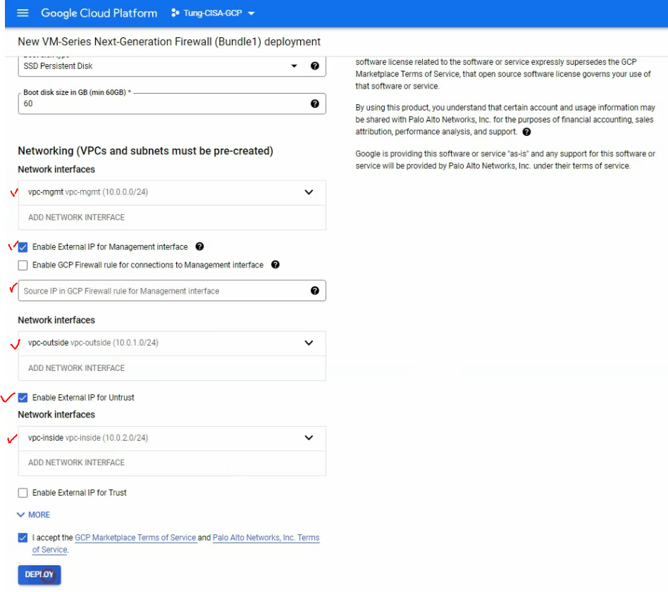
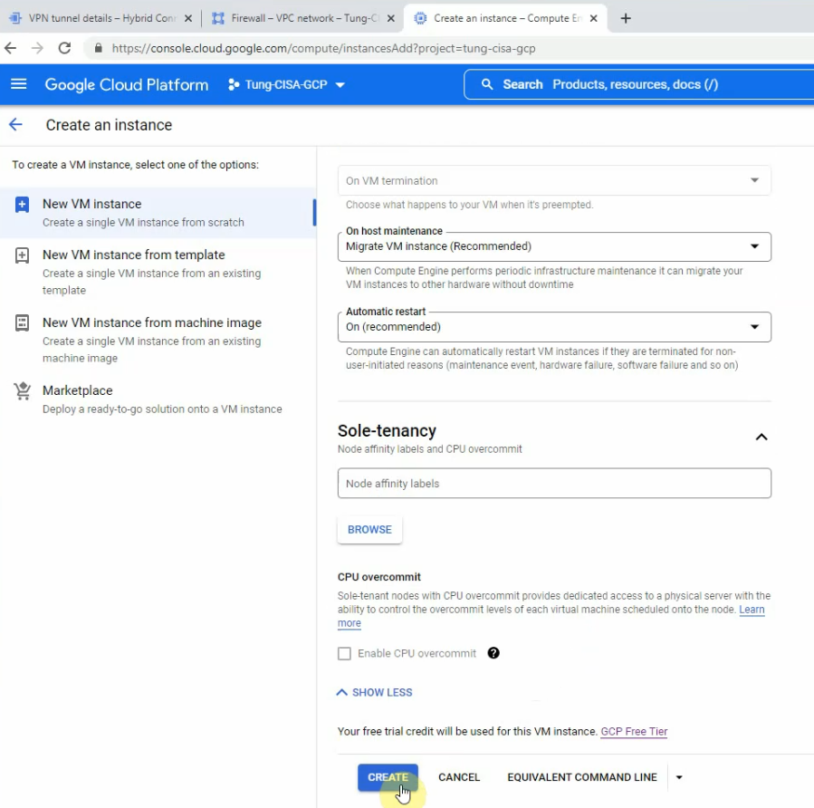
Select the interfaces like the following screenshot. Then, click “Deploy”.
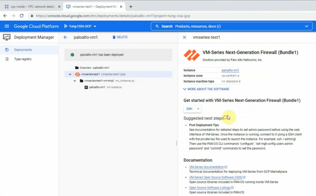
Wait a couple of minutes to see the “Palo Alto has been deployed” notification.
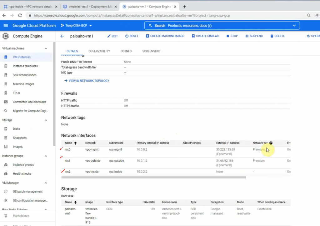
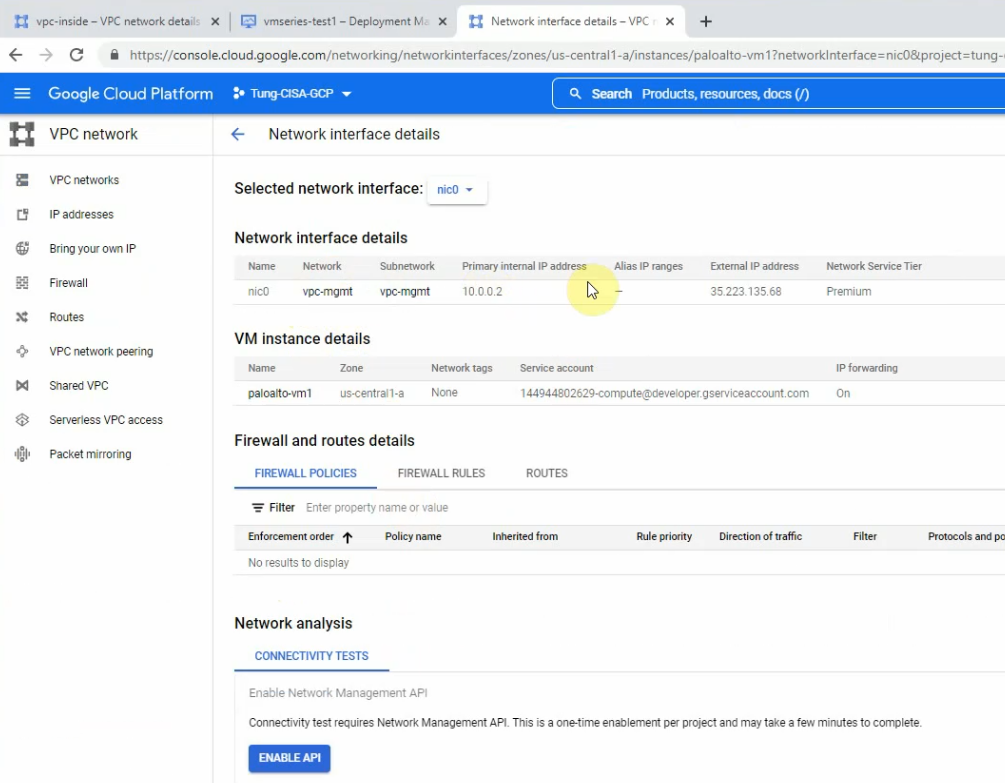
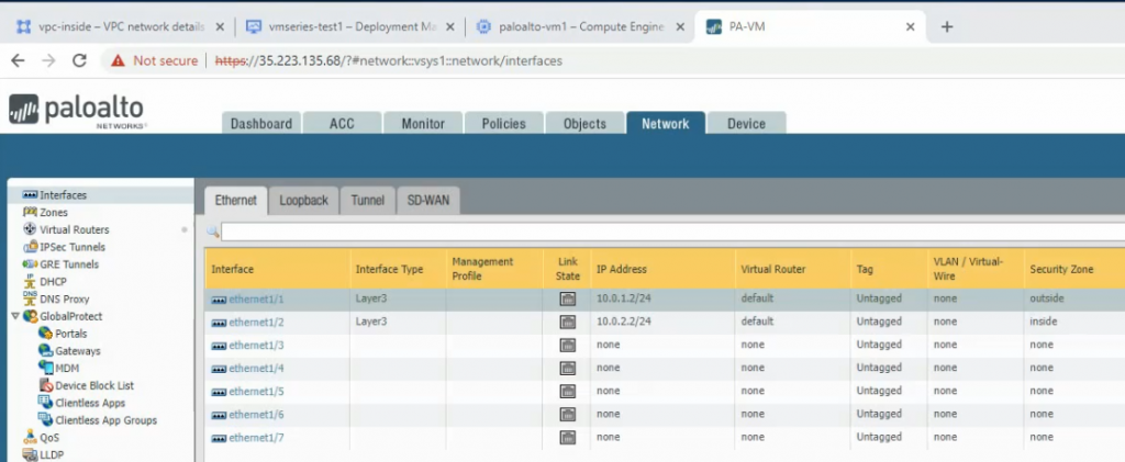
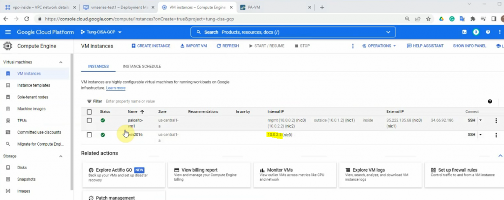
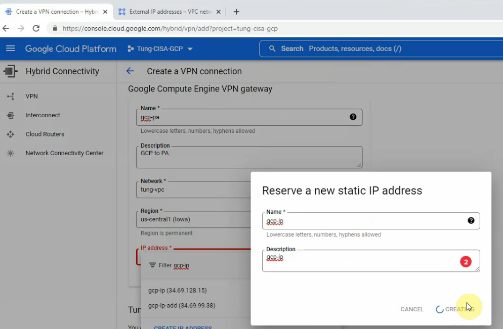
Get the external IP address of mgmt and outside interfaces.
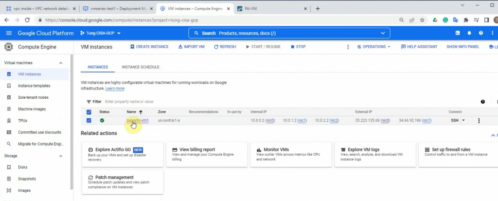
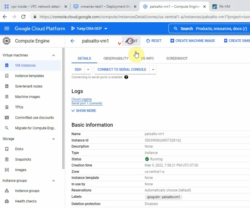
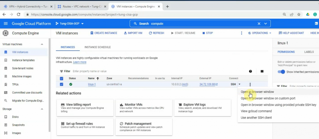
Compute Engine – VM instances – paloalto-vm1.
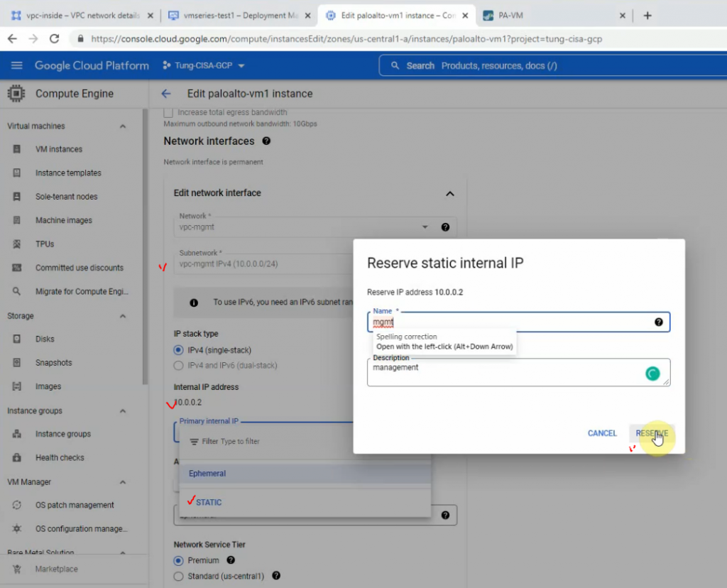
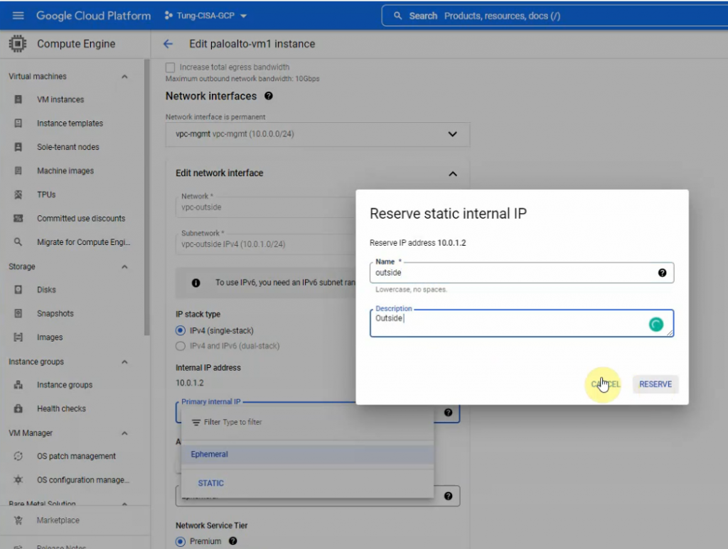
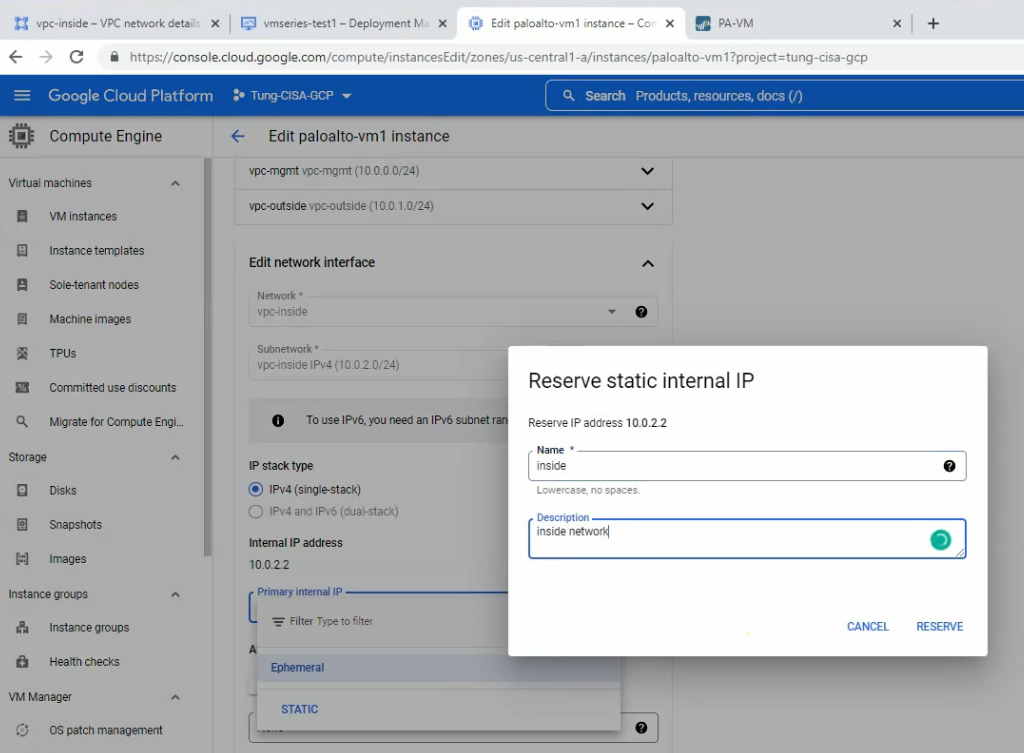
Click Edit.
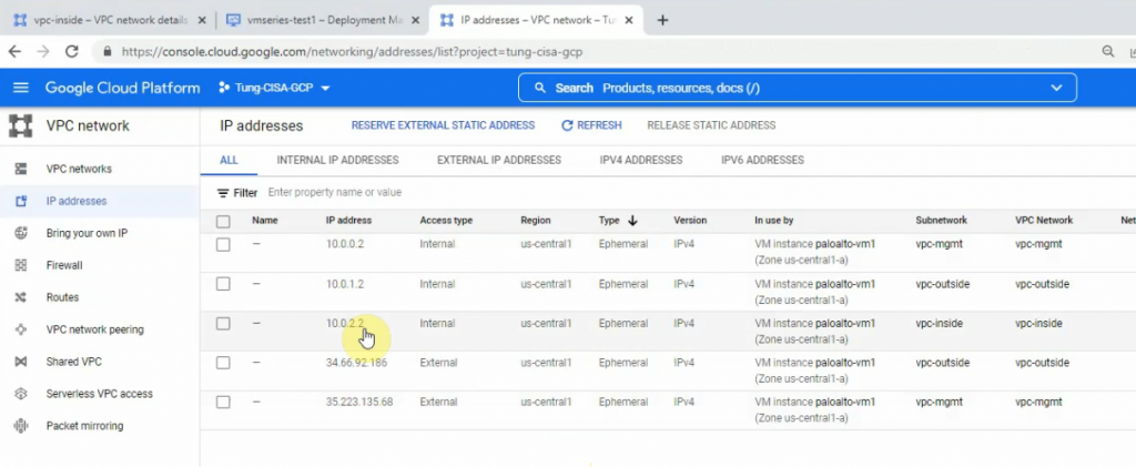
Reserve the static IP address 10.0.0.2, 10.0.1.2 and 10.0.2.2 for mgmt, outside and inside network on Palo Alto.
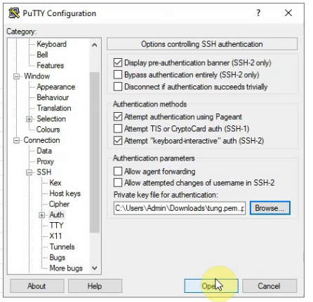
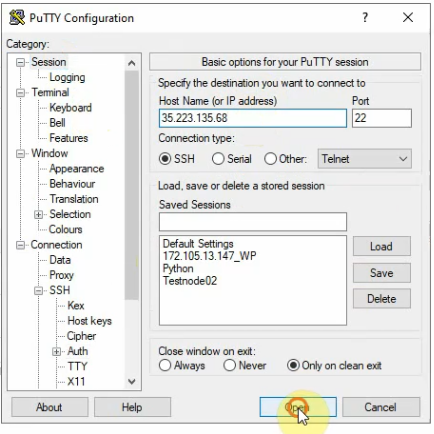
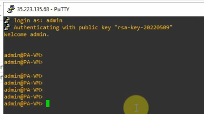
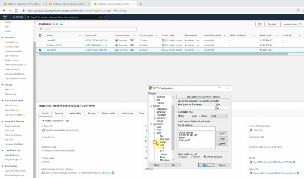
Open Putty and load the private key that you have saved in the previous step.
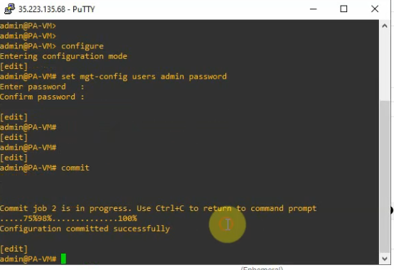
Set password for the admin user and commit.
configure
set mgt-config users admin password
commit
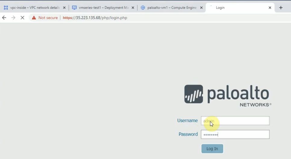
Open your web browser and enter https://35.223.135.68.
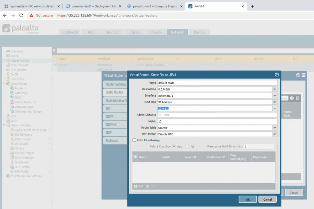
Create a default route on Palo Alto.
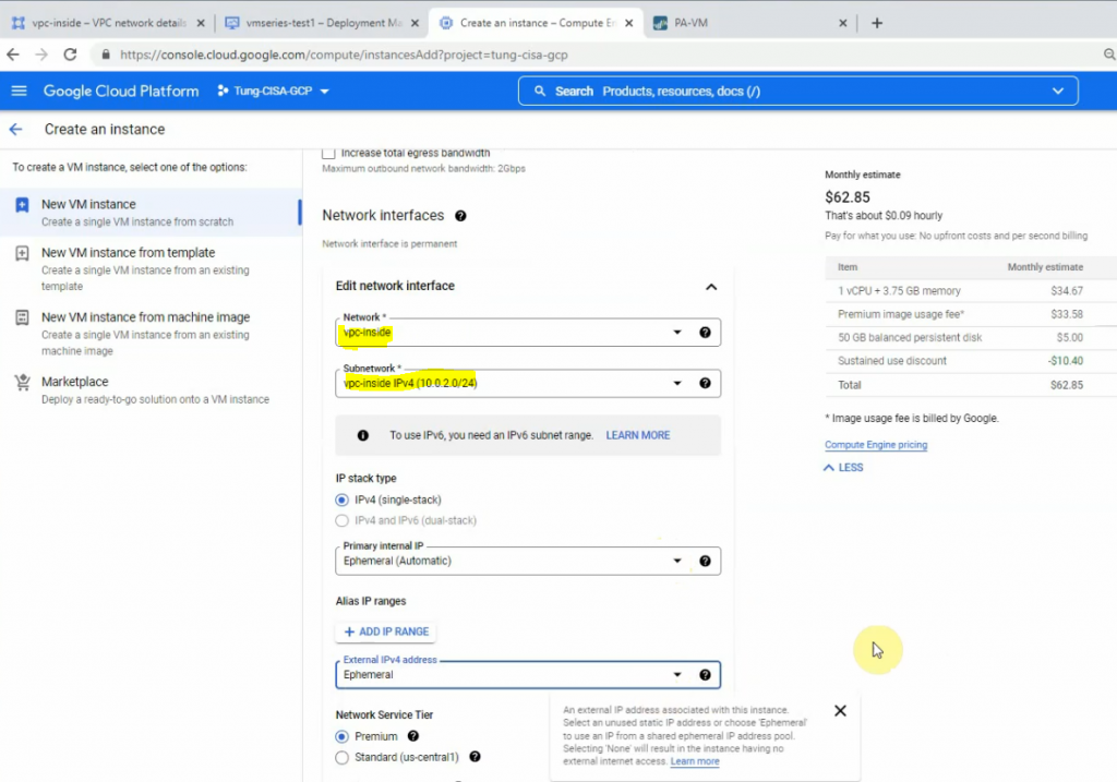
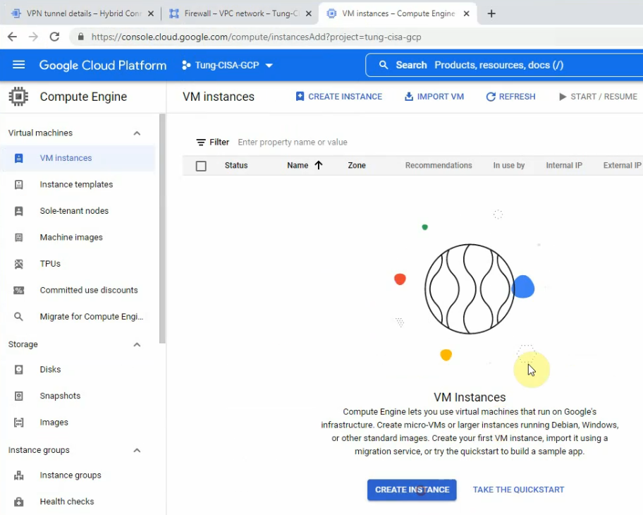
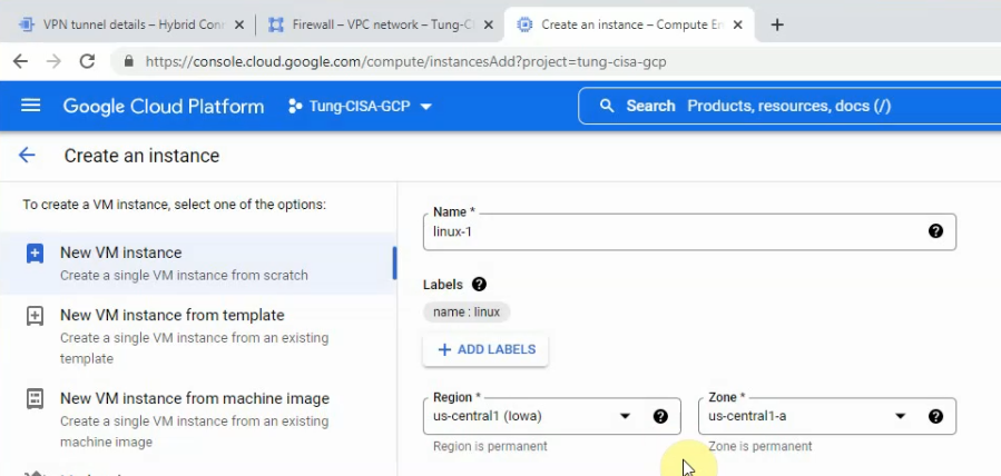
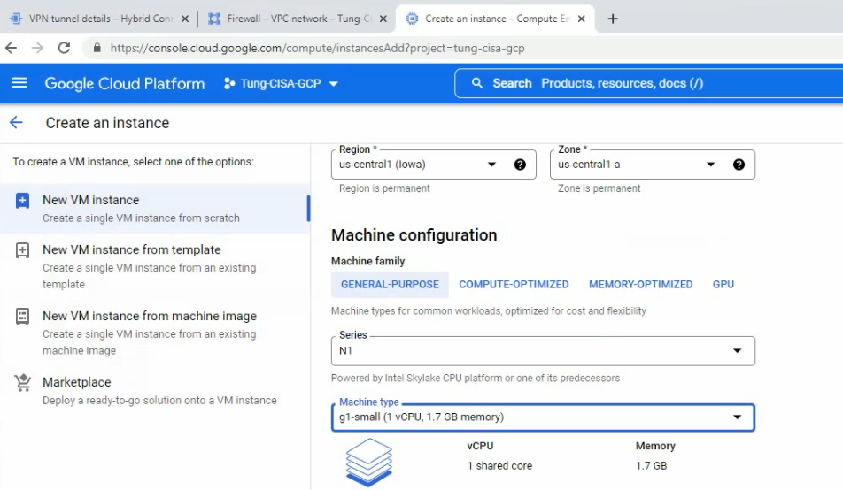
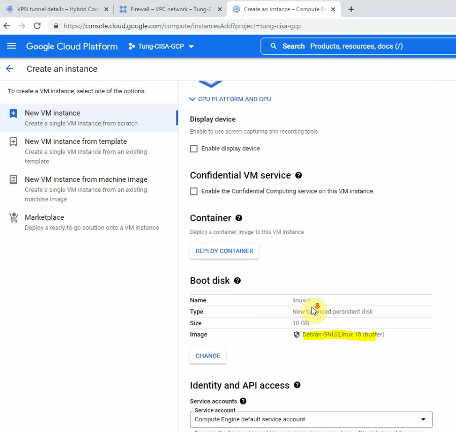
Go to Compute Engine – Create a new Windows 2016 VM.
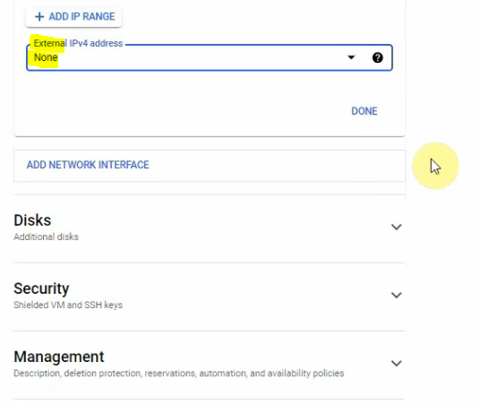
On External IP address, change from ephemeral to None. Then, click to create a VM.
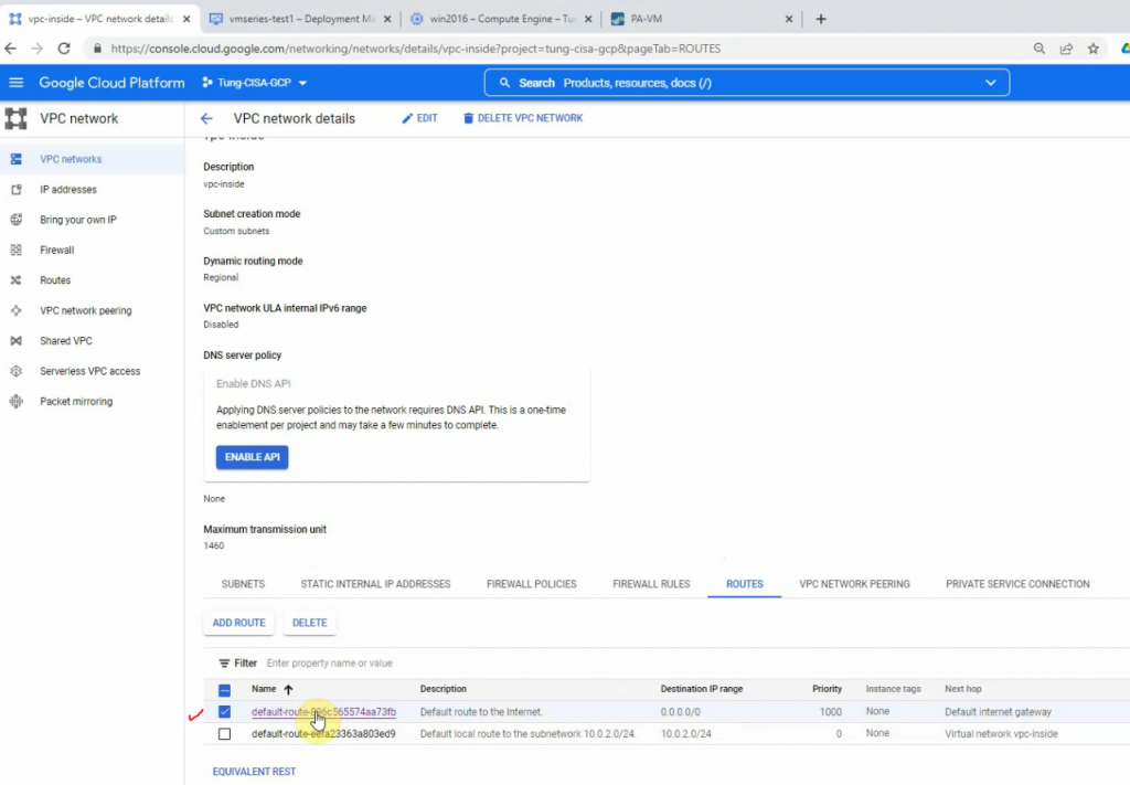
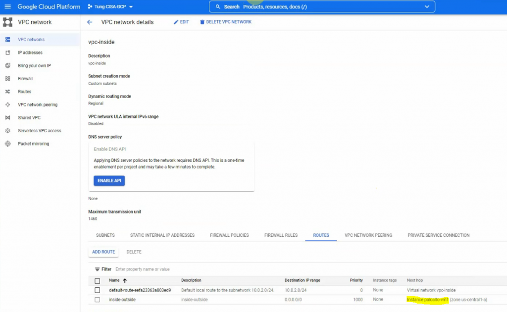
Back to the VPC network – Routes to change the default route of the inside network to the Palo Alto instance. Delete the highlighted route as the screenshot below.
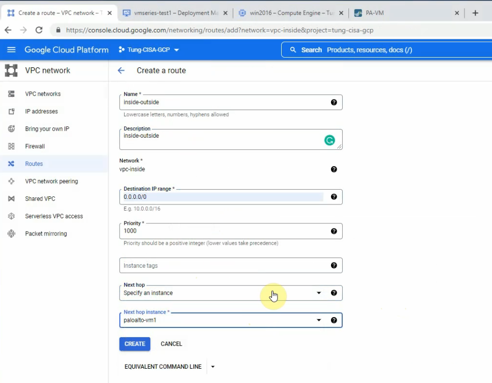
Create a new default route, and change the next hop instance from the internet gateway to use the Palo Alto instance.
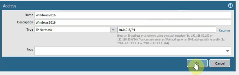
Create a new Windows 2016 instance object on Palo Alto.
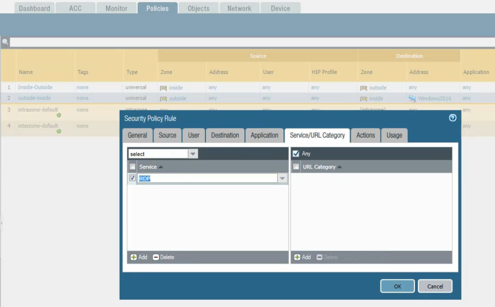
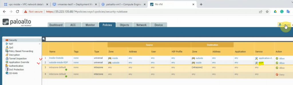
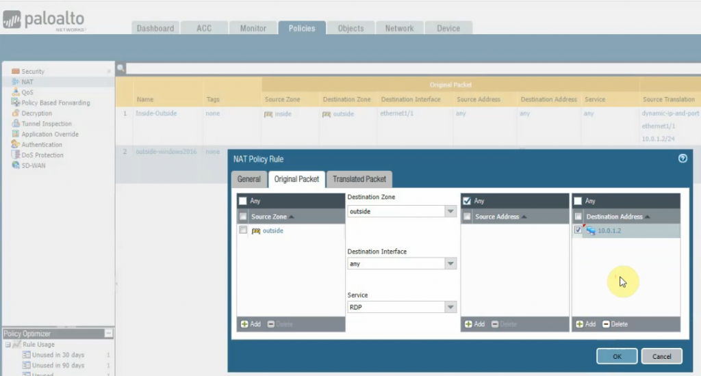
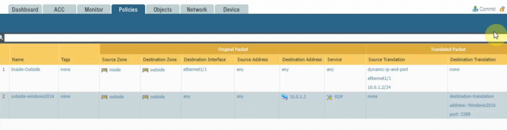
Create both access rules to allow traffic from the inside network to the outside, and from the Internet to the Windows 2016 VM.
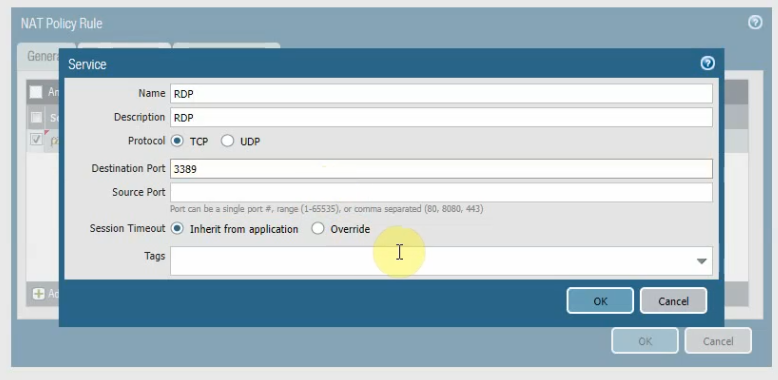
The outside network to RDP service on the inside network.
Create SNAT to allow traffic from the inside network to the outside network via the Palo Alto.
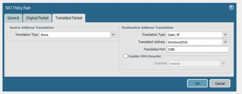
Create a DNAT rule to allow RDP traffic from the Internet to Palo Alto and DNAT to Windows 2016 instance.
Click commit.
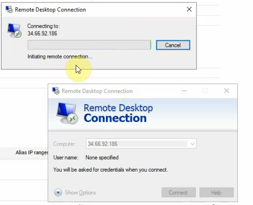
Open RDP on a Windows machine and enter the public IP address of the vpc-outside network on Palo Alto.
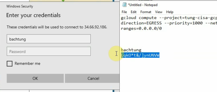
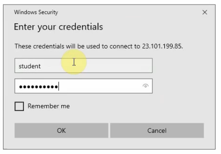
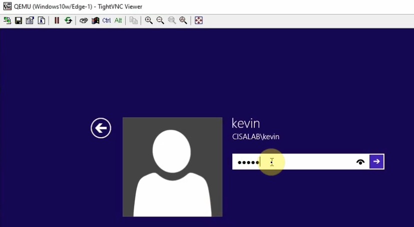
Enter your username and password.
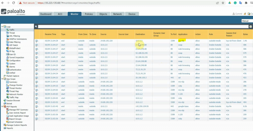
We can see the RDP traffic in Palo Alto.
The Windows instance is able to access the Internet via Palo Alto.
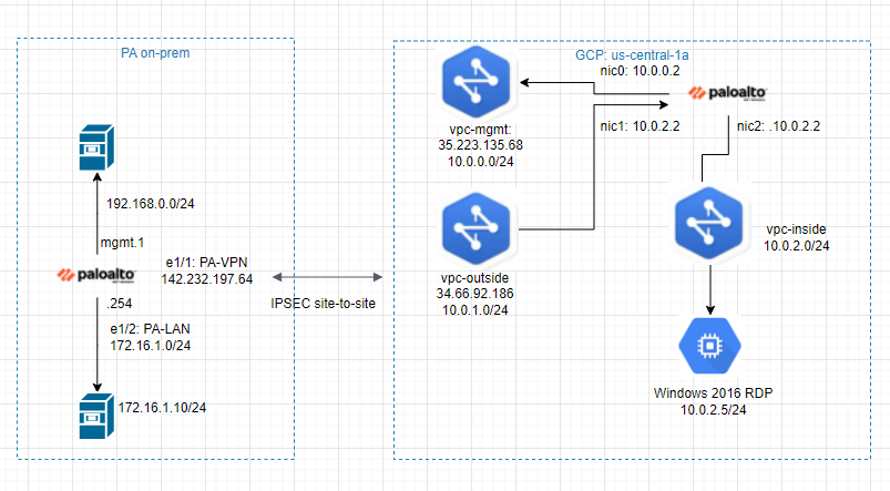
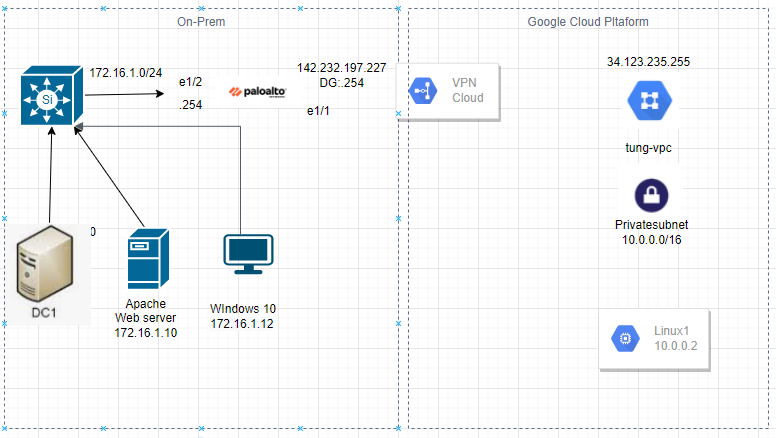
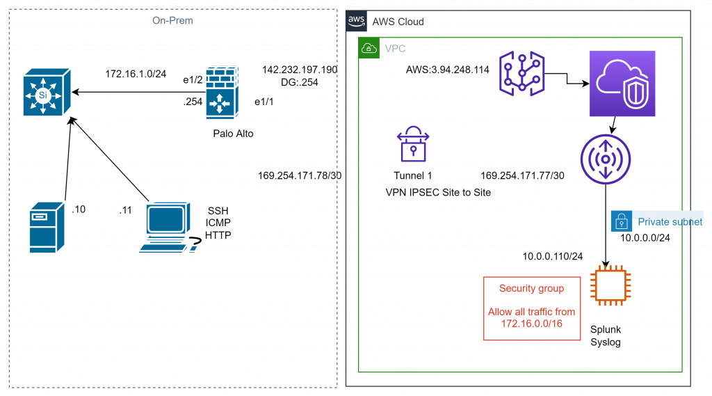
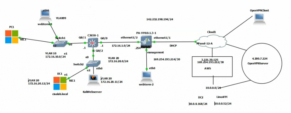
This is a diagram that I have used to deploy this lab.
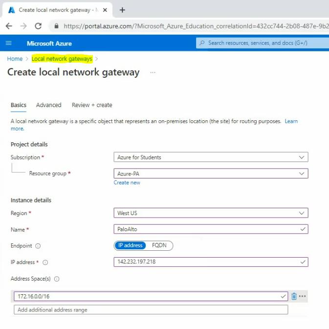
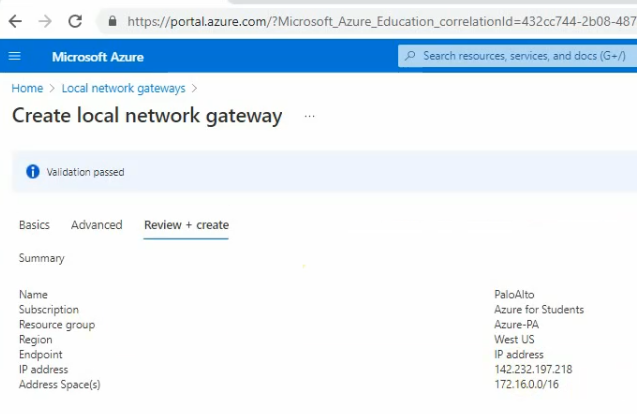
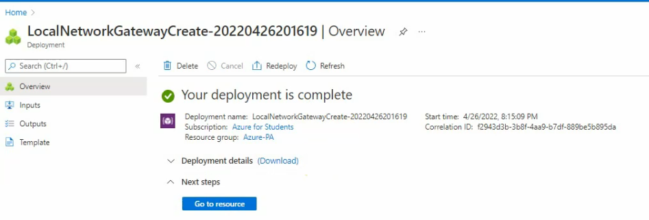
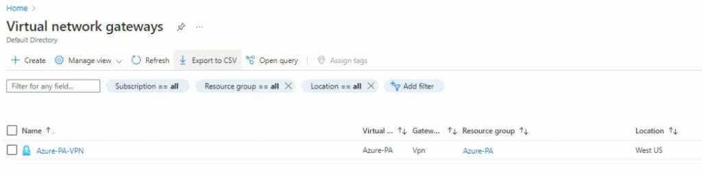
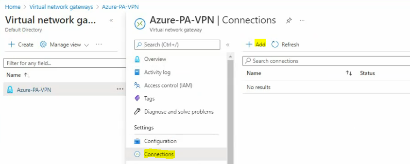
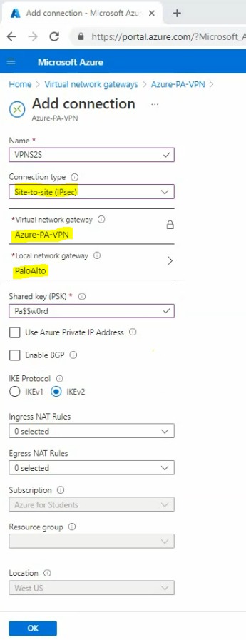
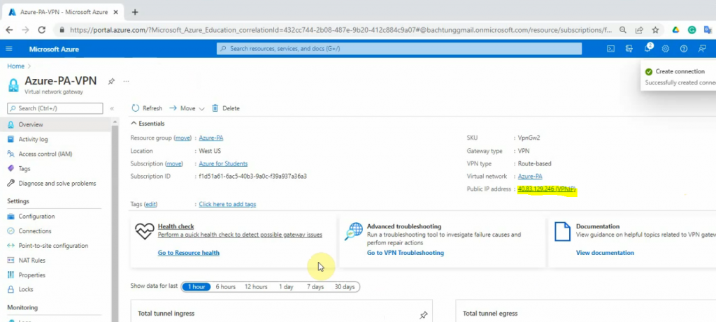
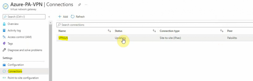
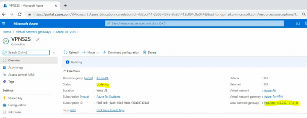
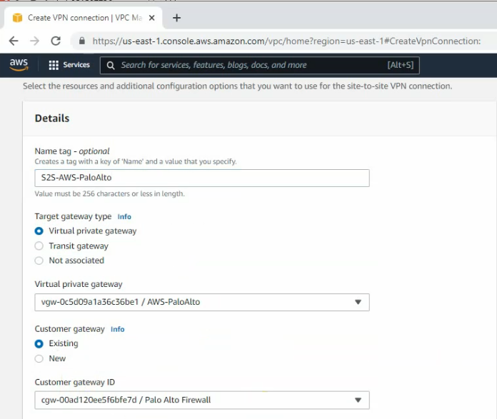
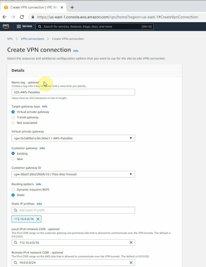
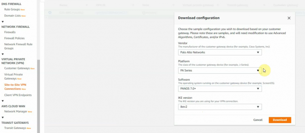
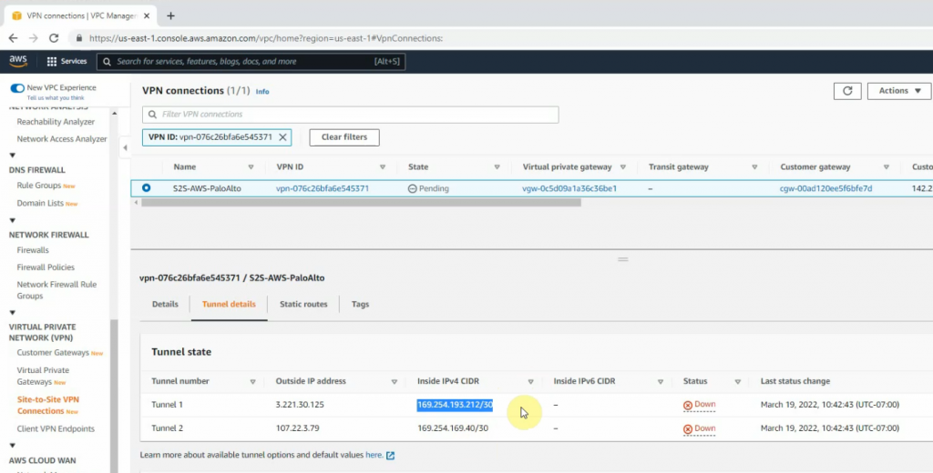
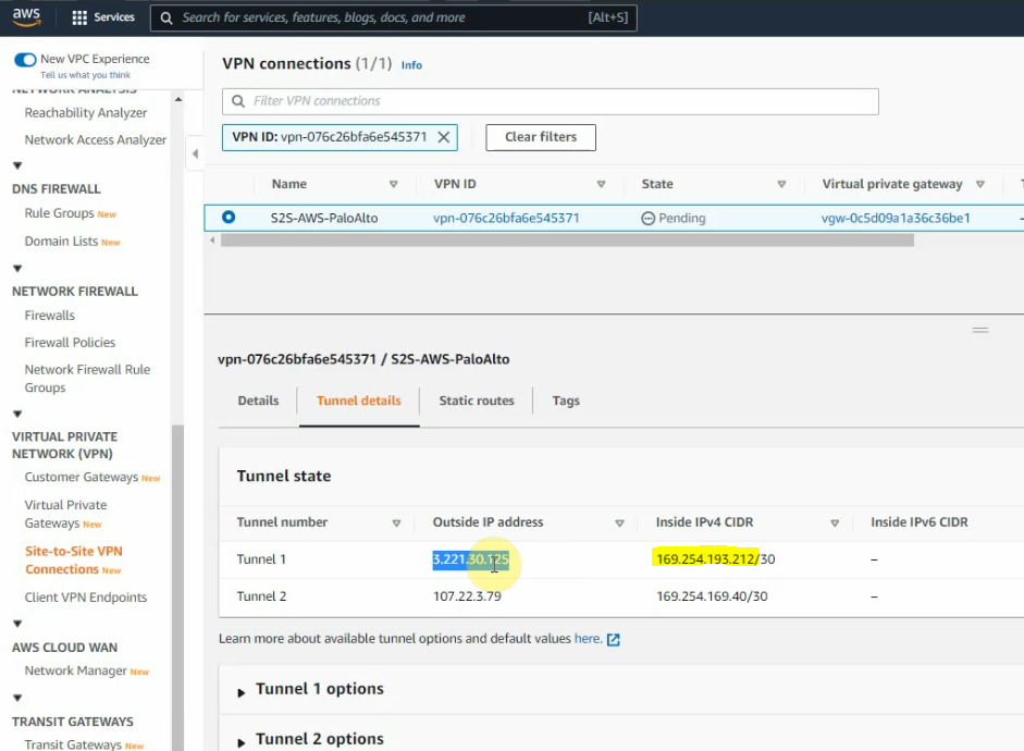
We need to deploy a VPN site to site between Palo Alto on-prem and AWS.
On AWS.
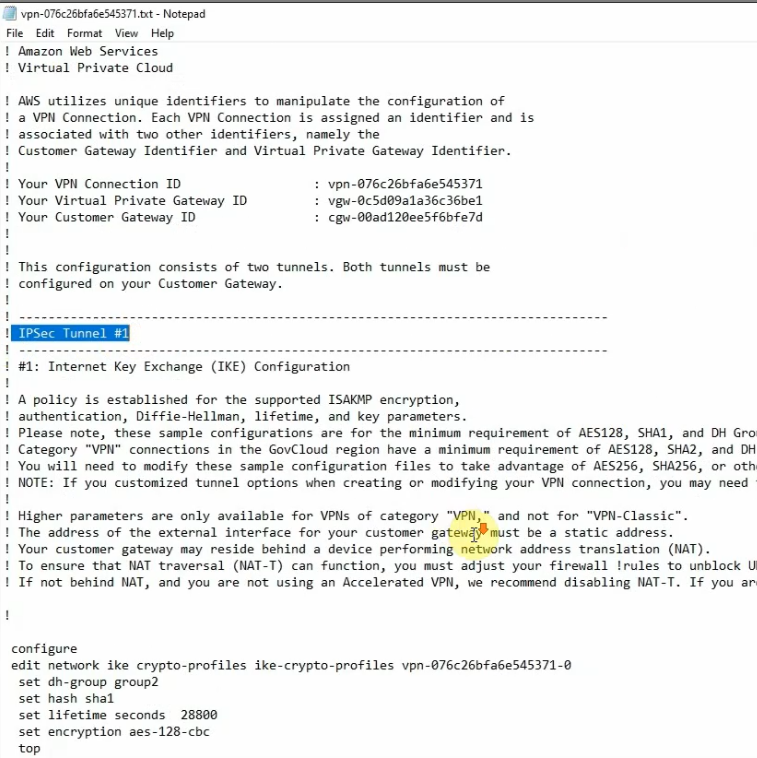
On Palo Alto.
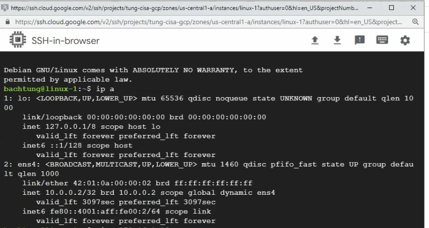
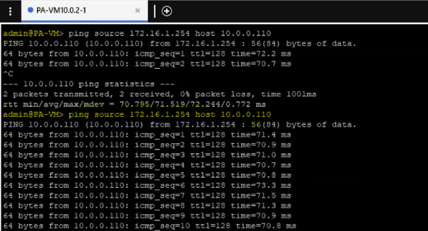
Pings Splunk instance (10.0.0.110) via ethernet 1/2 interface.
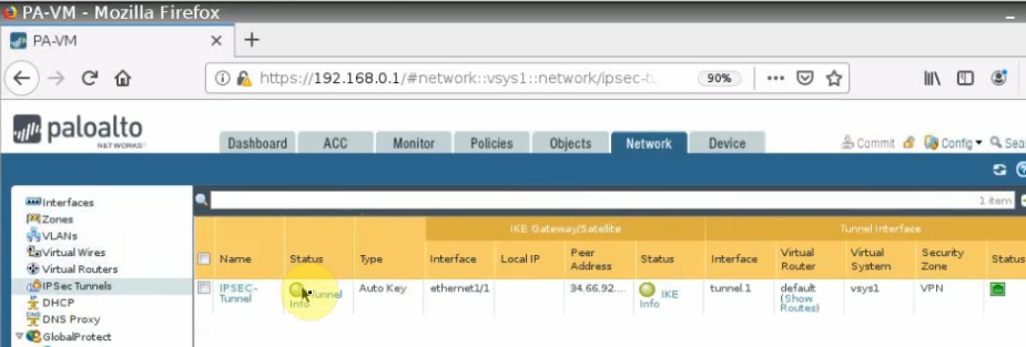
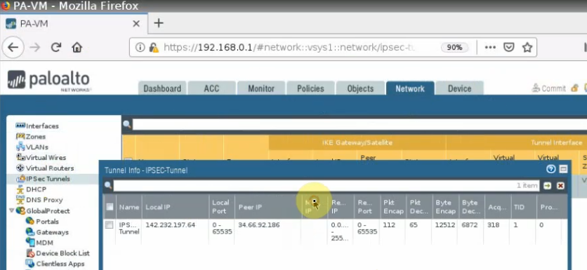
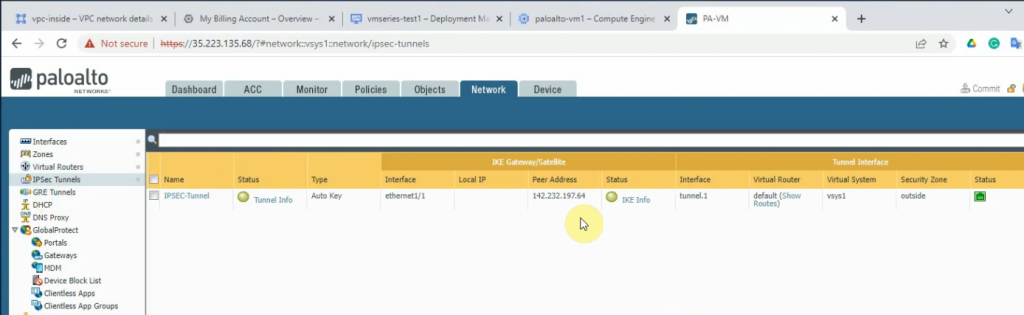
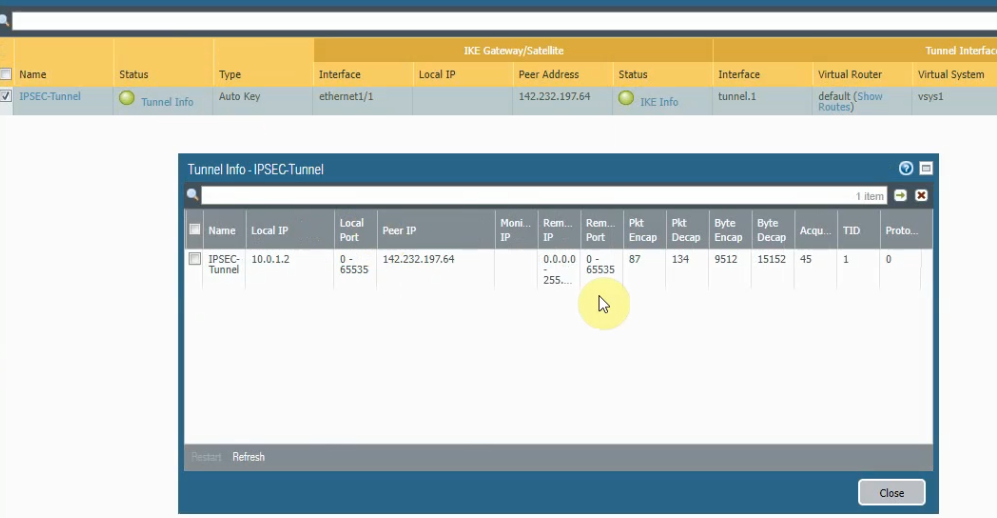
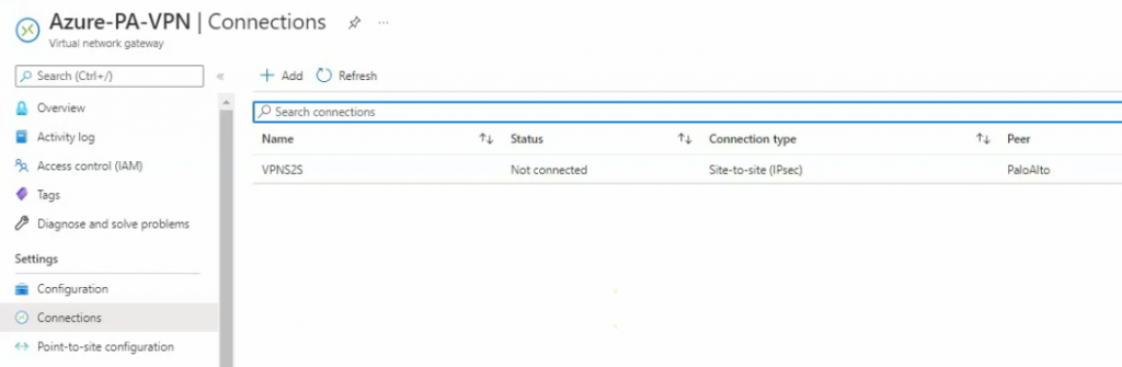
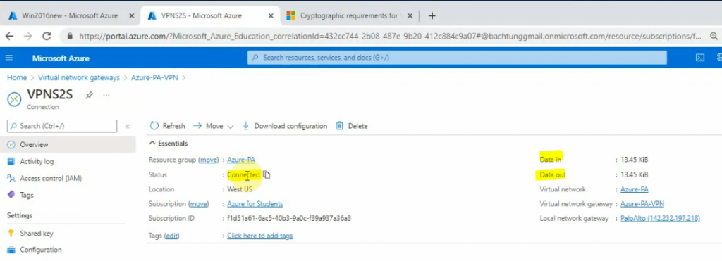
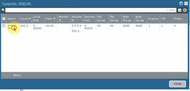
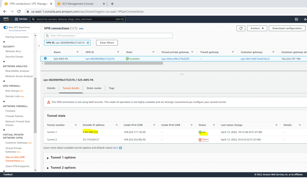
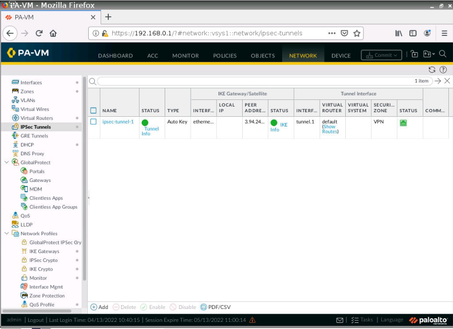
The VPN site-to-site tunnel is up in Palo Alto.
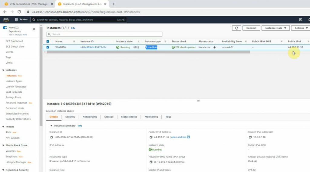
Set up a new Windows 2016 instance with 4 GB memory to run Splunk Enterprise on AWS.
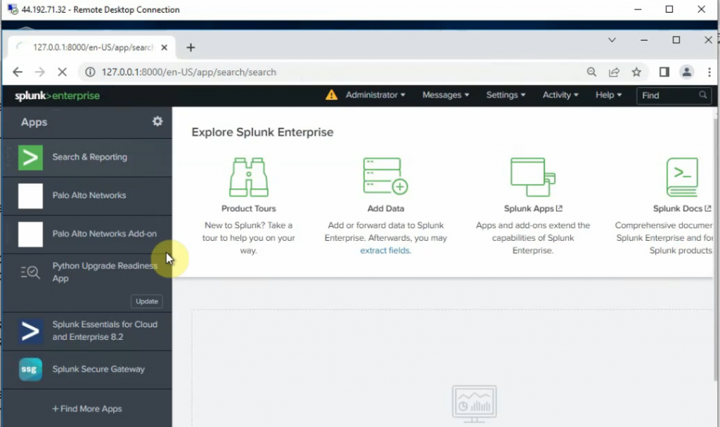
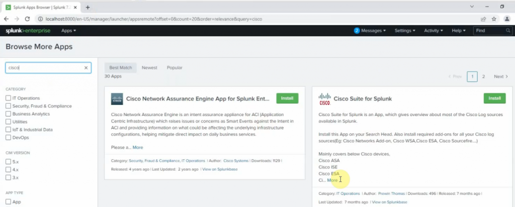
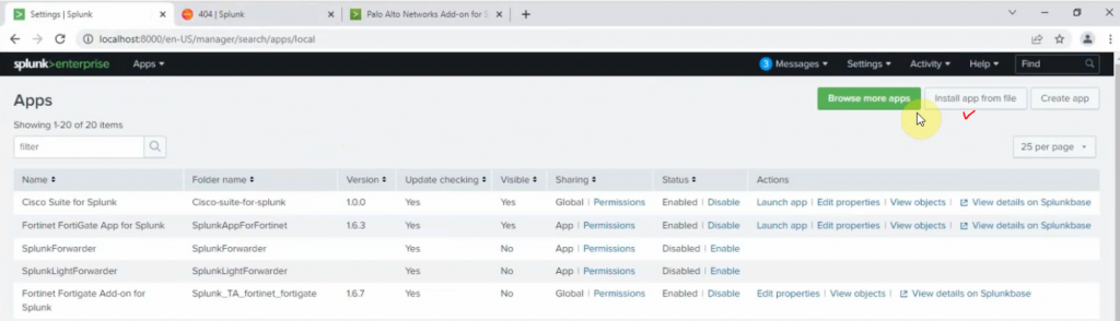
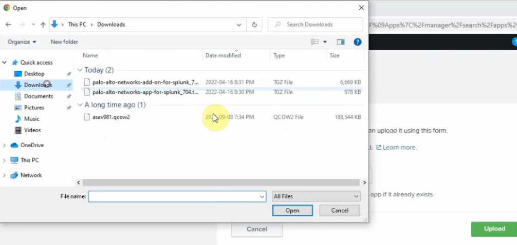
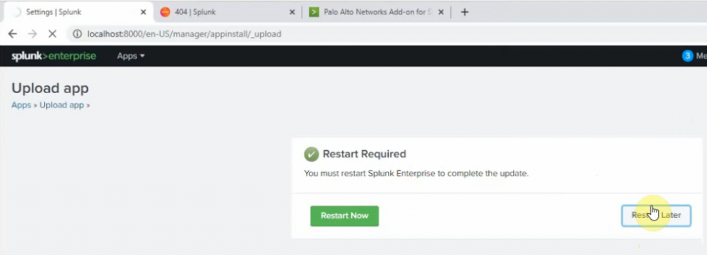
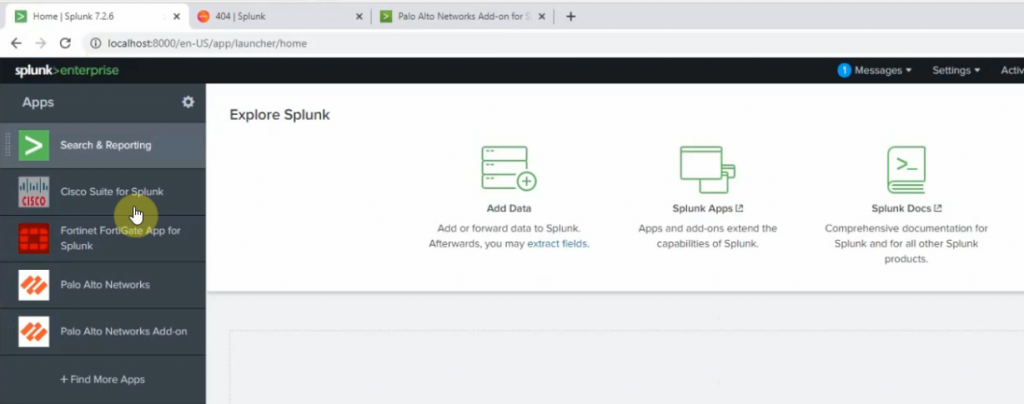
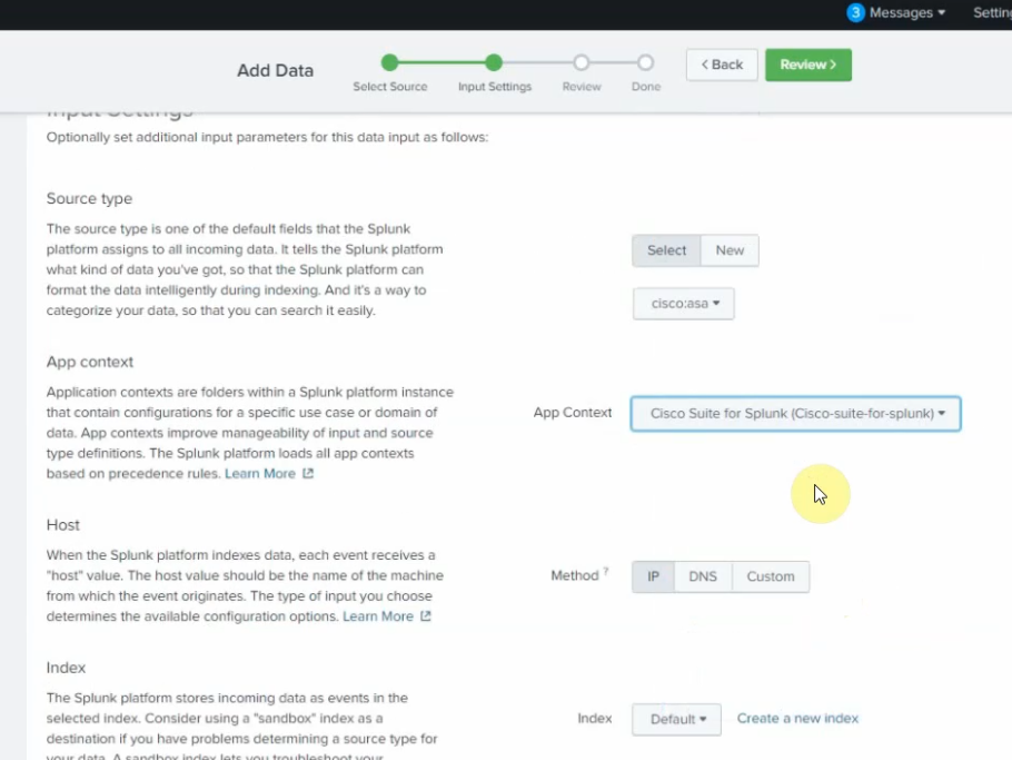
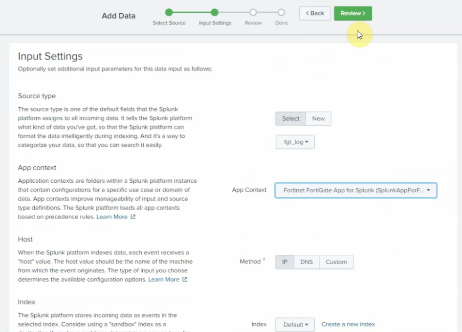
RDP to the instance and install Splunk Enterprise. Then, add Splunk for Palo Alto on this instance.
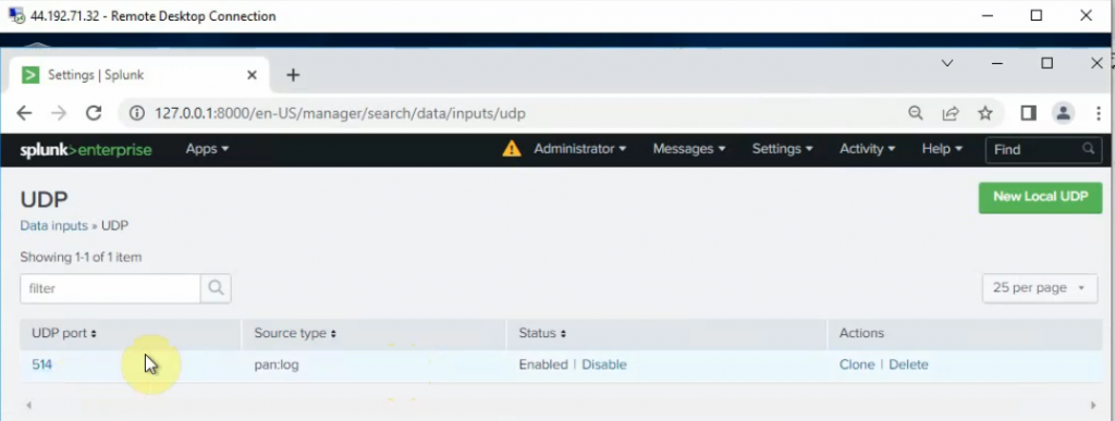
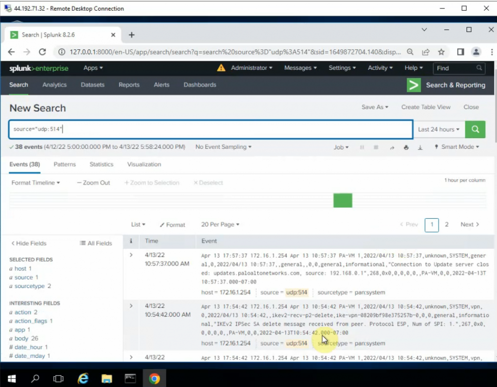
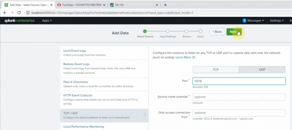
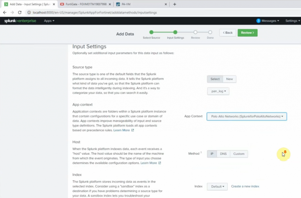
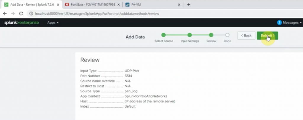
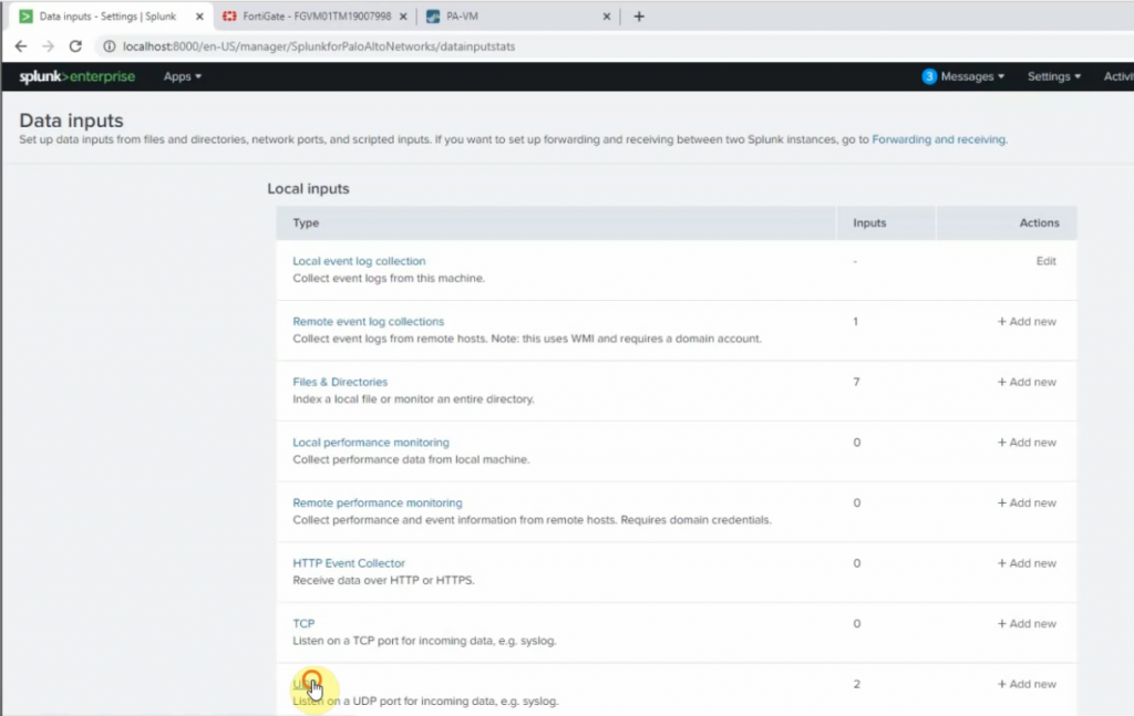
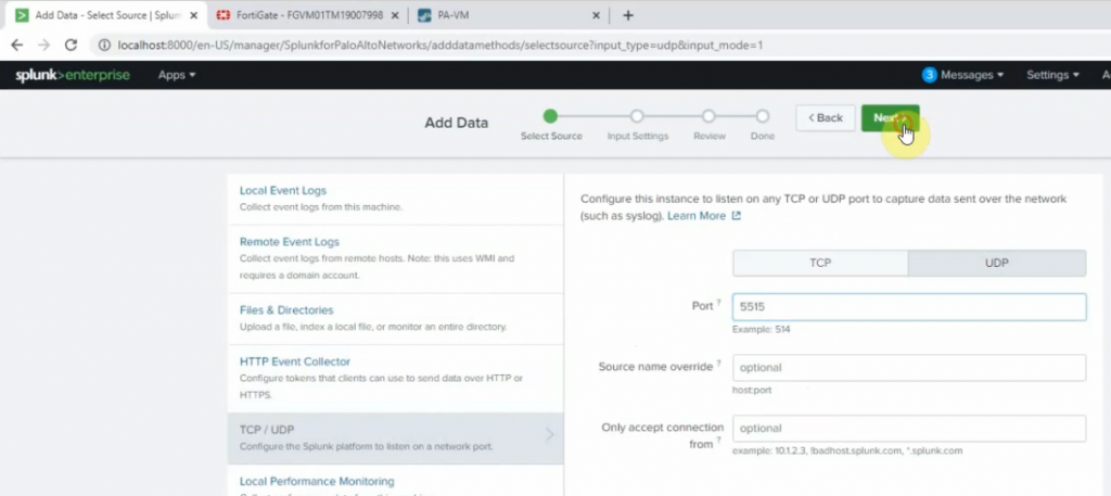
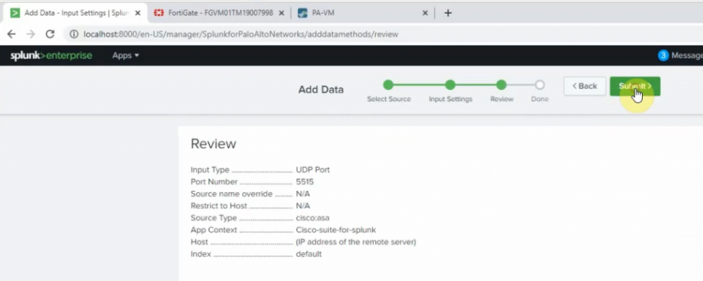
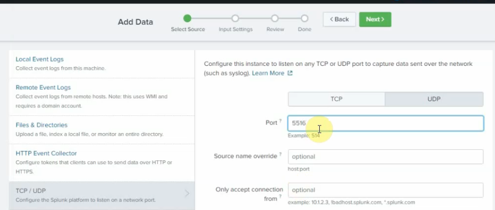
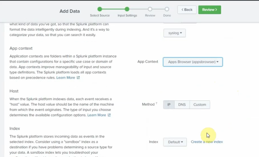
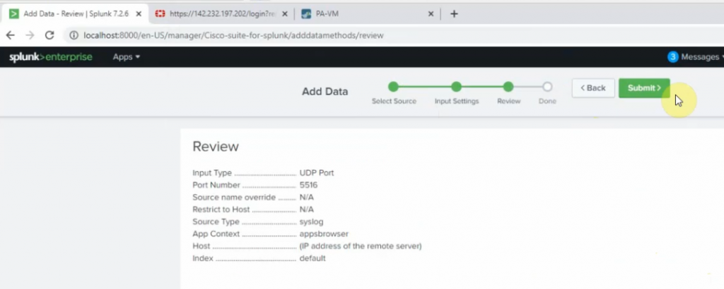
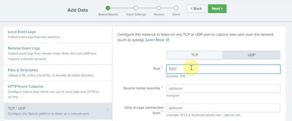
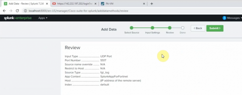
Configure Splunk to get Palo Alto logs via UDP port 514.
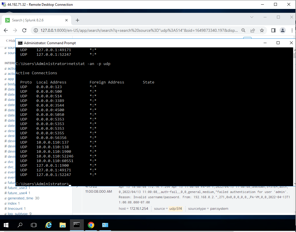
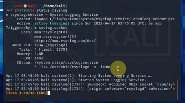
Check the UDP 514 port is running on the Splunk instance.
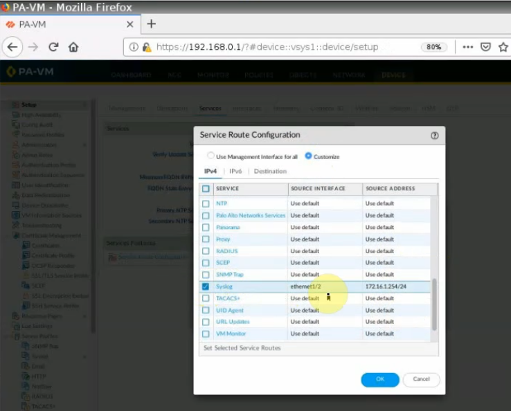
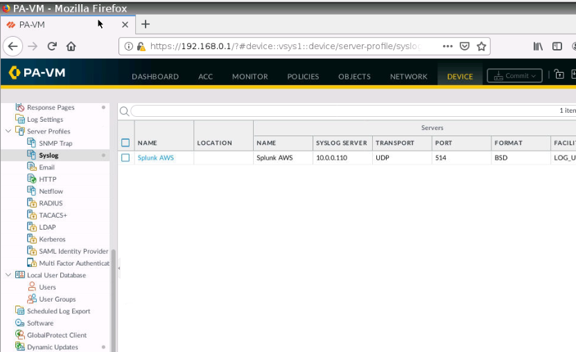
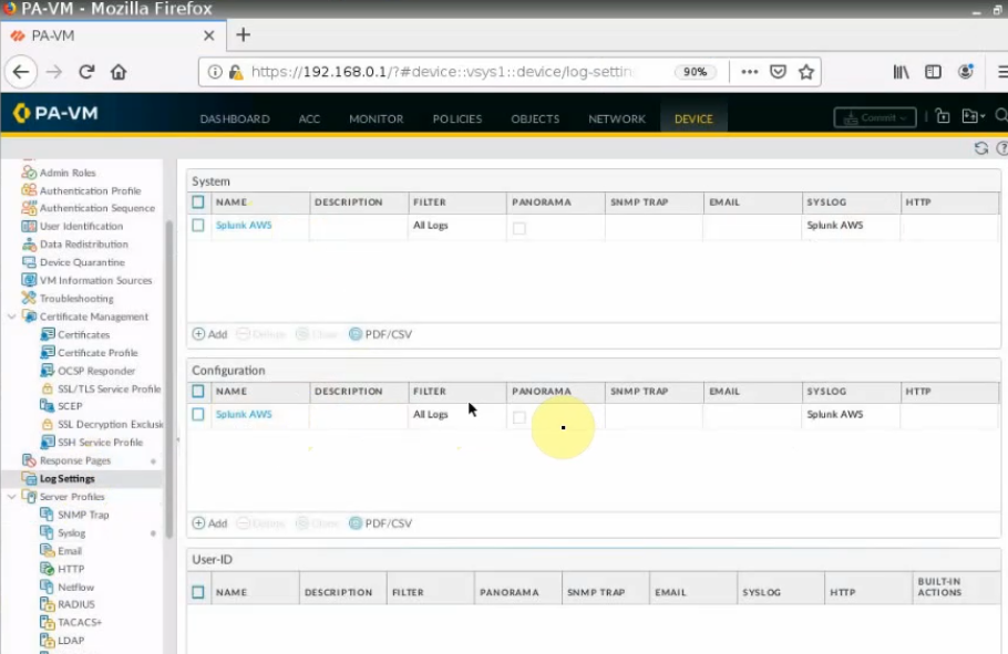
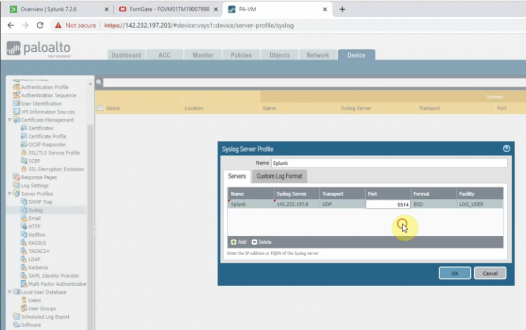
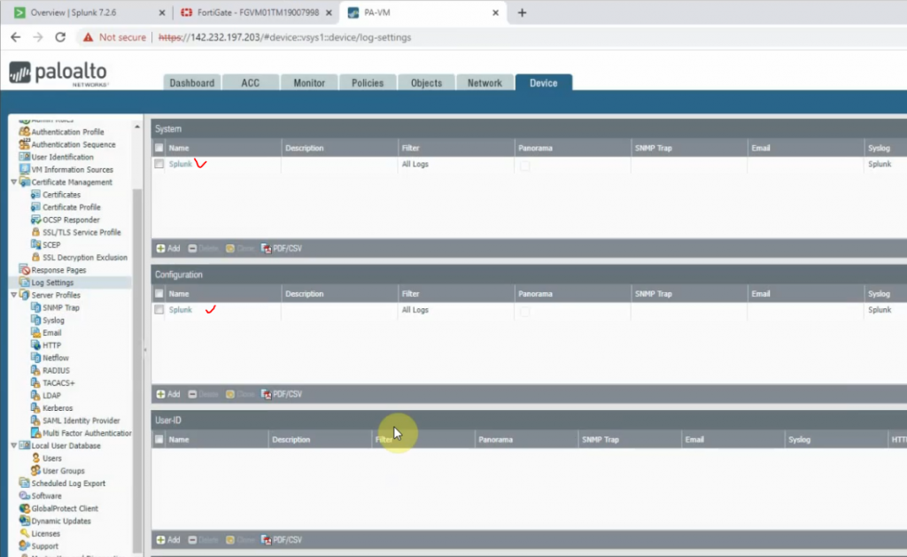
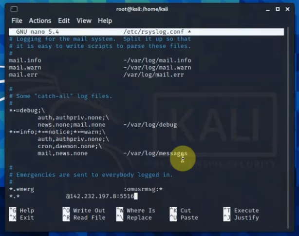
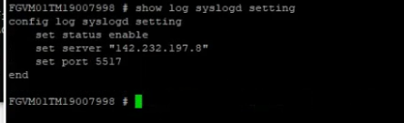
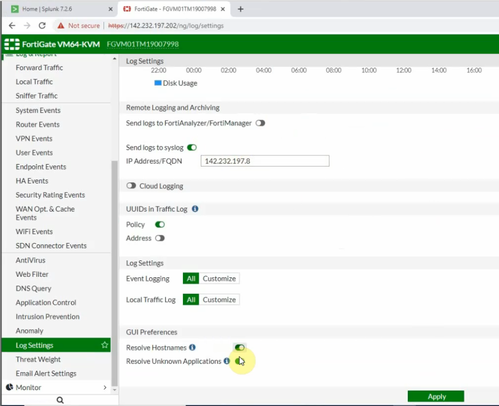
Go to Palo Alto, and configure Syslog to send logs to Splunk.
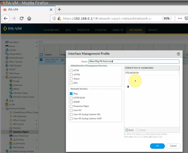
By default, Palo Alto uses a management interface to send logs. We need to change the interface to allow Palo Alto to send logs via ethernet1/2 (LAN interface).
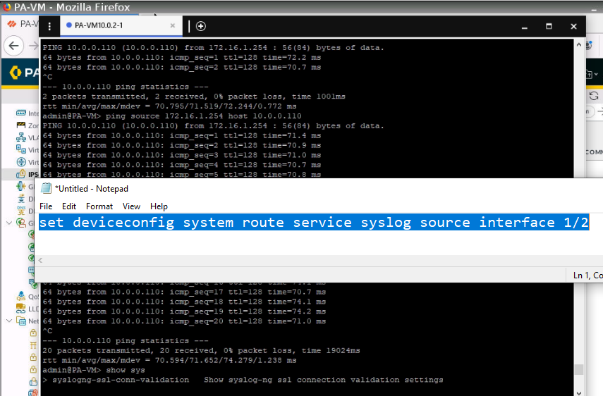
Log on PA console, type configure, and the command below to change the interface to send logs.
set deviceconfig system route service syslog source interface e1/2
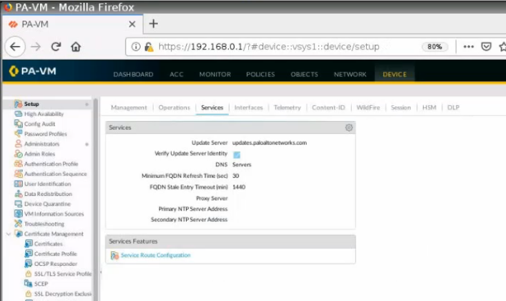
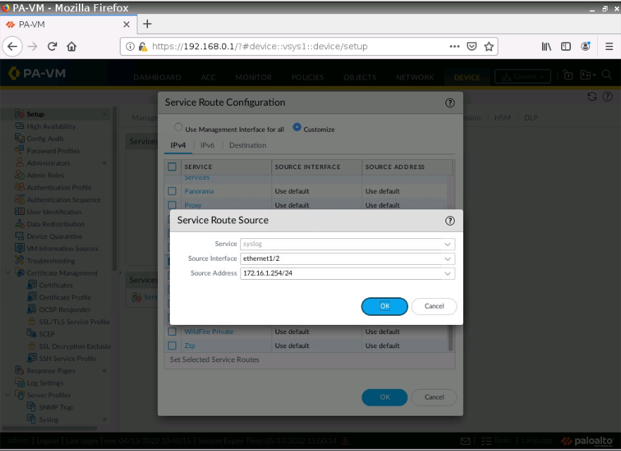
Also, we can go to Device – Setup – Service Route Configuration – Syslog. Configure the source interface and source IP address like the following screenshot.
Configure Syslog on Palo Alto.
IP address: 10.0.0.110 (Splunk instance)
Port: 514 UDP
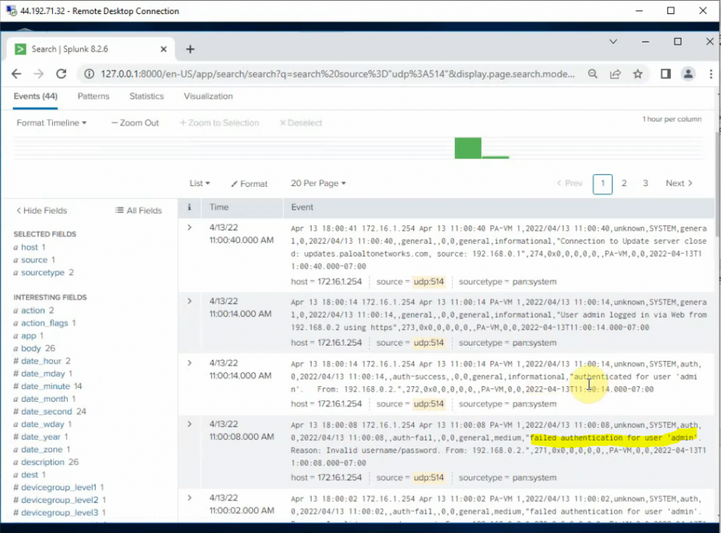
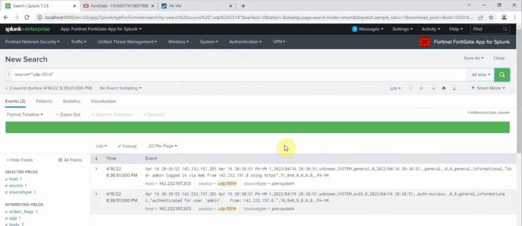
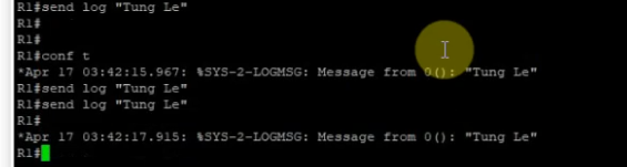
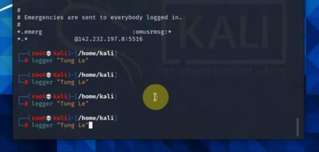
Log off and enter the wrong password on Palo Alto. Log back into Palo Alto to generate logs to send to Splunk.
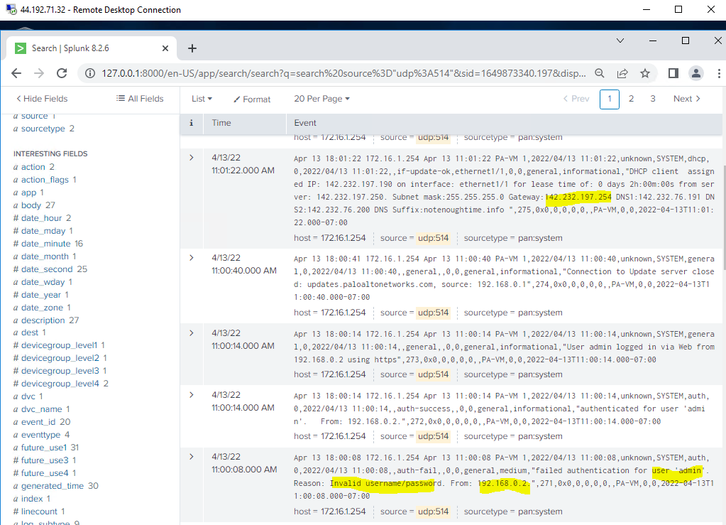
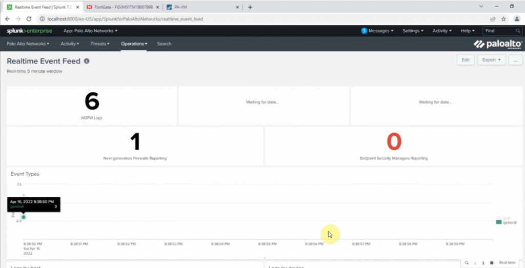
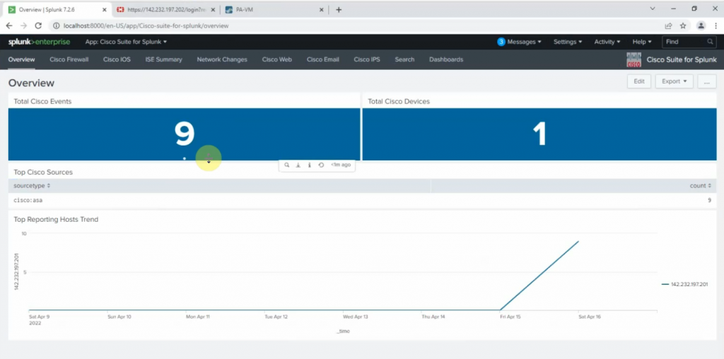
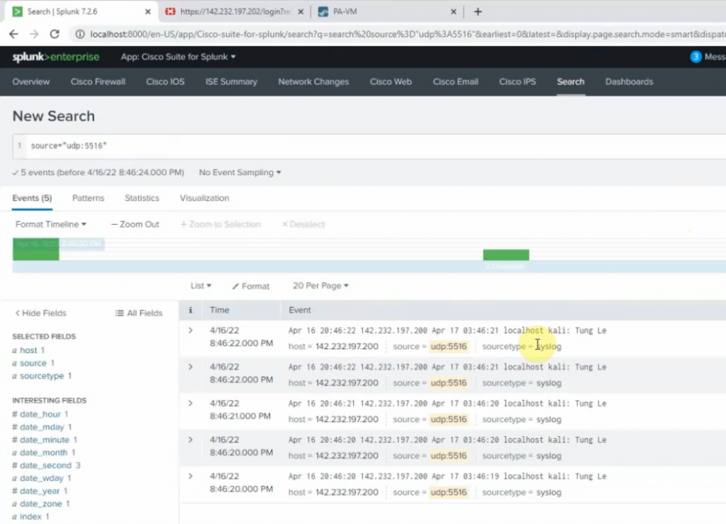
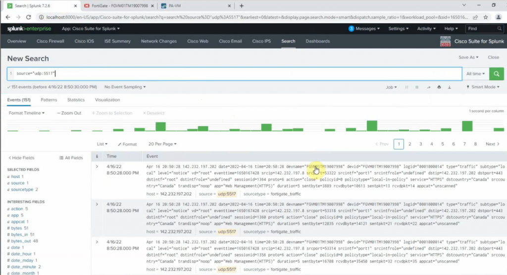
We can see “failed authentication log” events have been generated on Splunk.
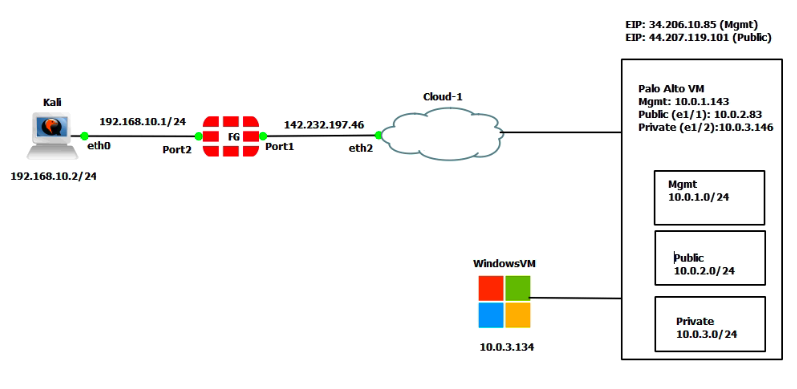
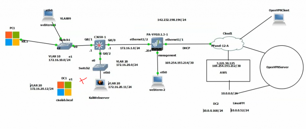
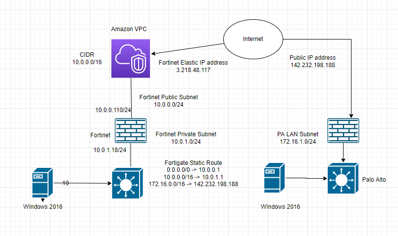
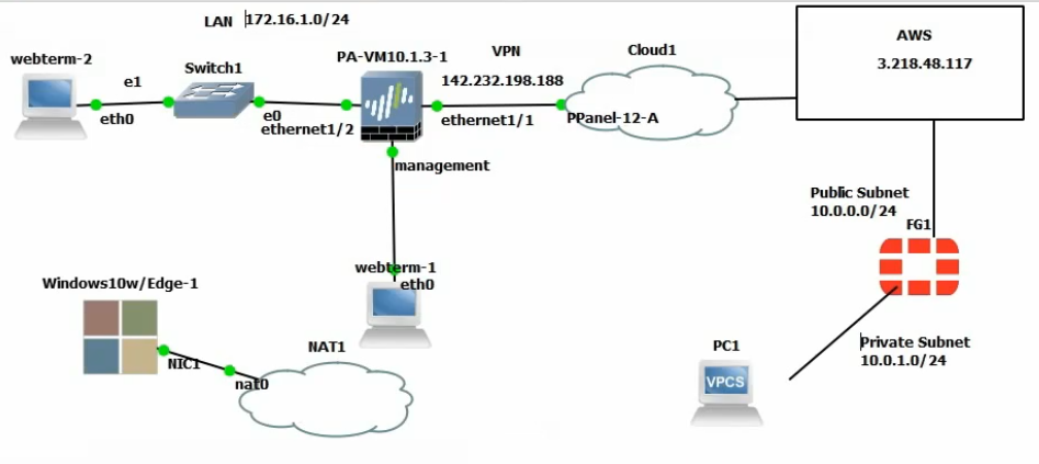
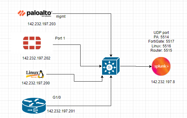
This is a diagram to show how to create a VPN site to site connection from PA on-prem and FG on AWS.
In this lab:
Create a VPC, subnets, Internet gateway, route tables.
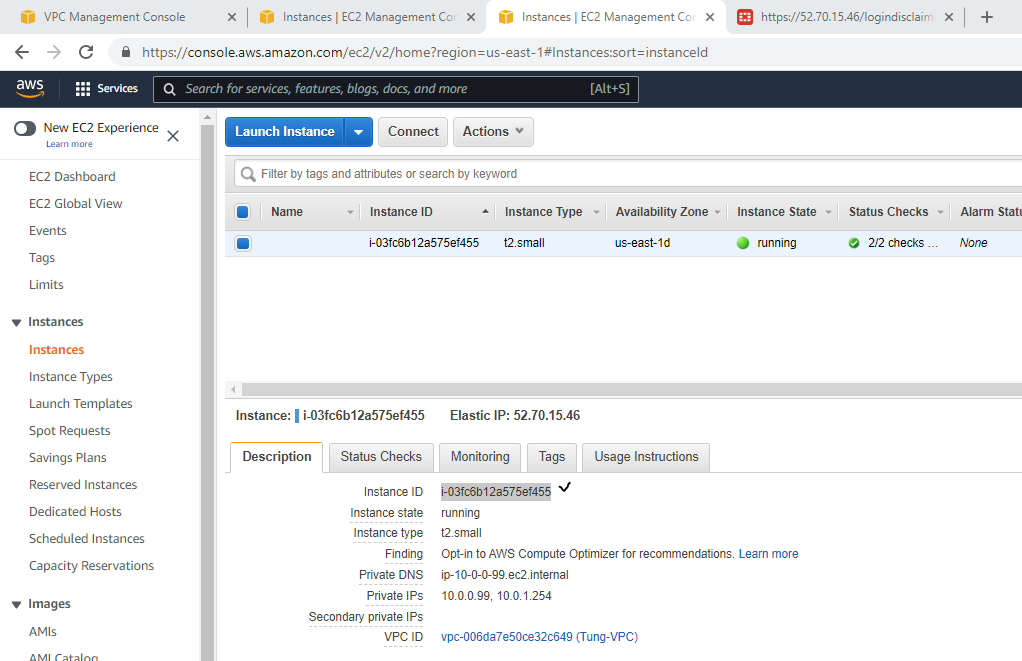
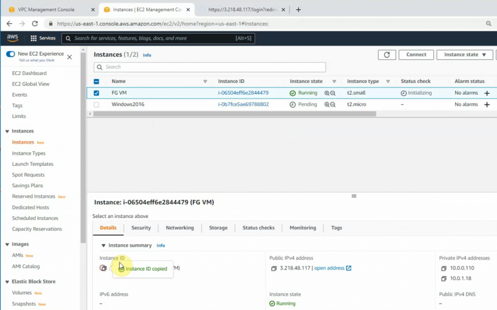
Create a FortiGate VM and Windows 2016 instance on AWS
Configure Palo Alto
Create VPN site to site between both sites PA and FortiGate
Allow Windows 2016 instance to access the Internet via FortiGate. Also, allow RDP to this machine via the Internet by using FortiGate.
Test ping traffic between both sites.
Allow a machine on the PA LAN subnet to access the Internet and the Windows 2016 instance on AWS.
Create a new SSLVPN portal on AWS and test to access the portal via SSLVPN.
+ Below are a couple of steps to deploy FortiGate on AWS.
Create a new VPC.
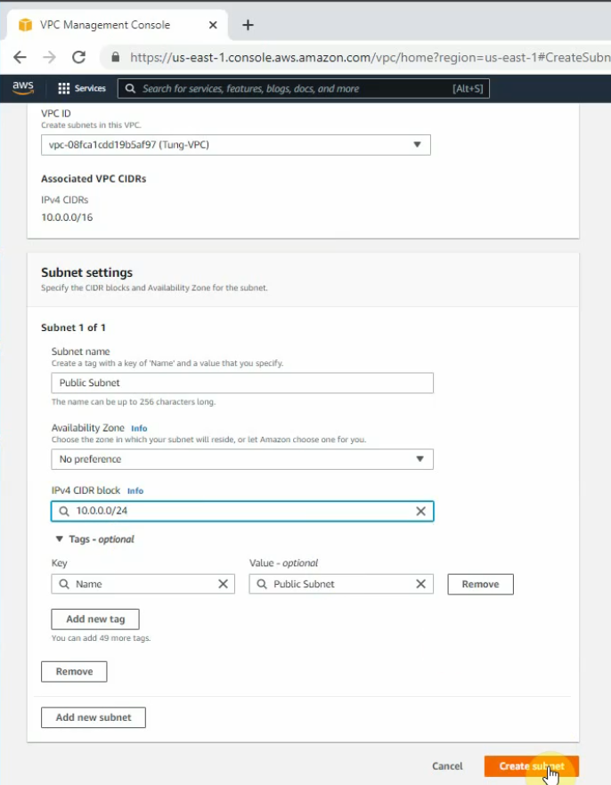
Create a public subnet.
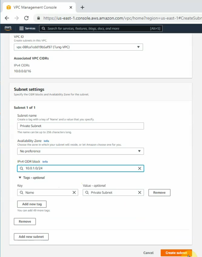
Create a private subnet.
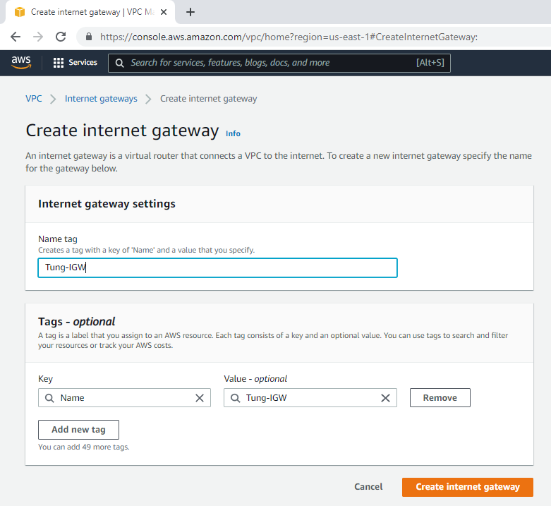
Create an Internet gateway.
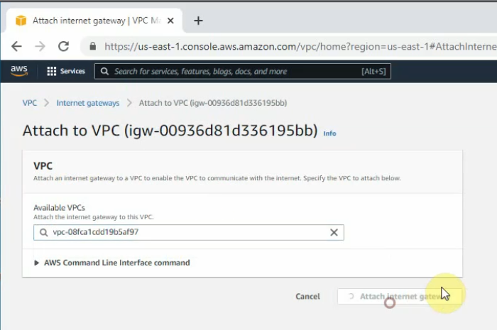
Attach the gateway to your VPC.
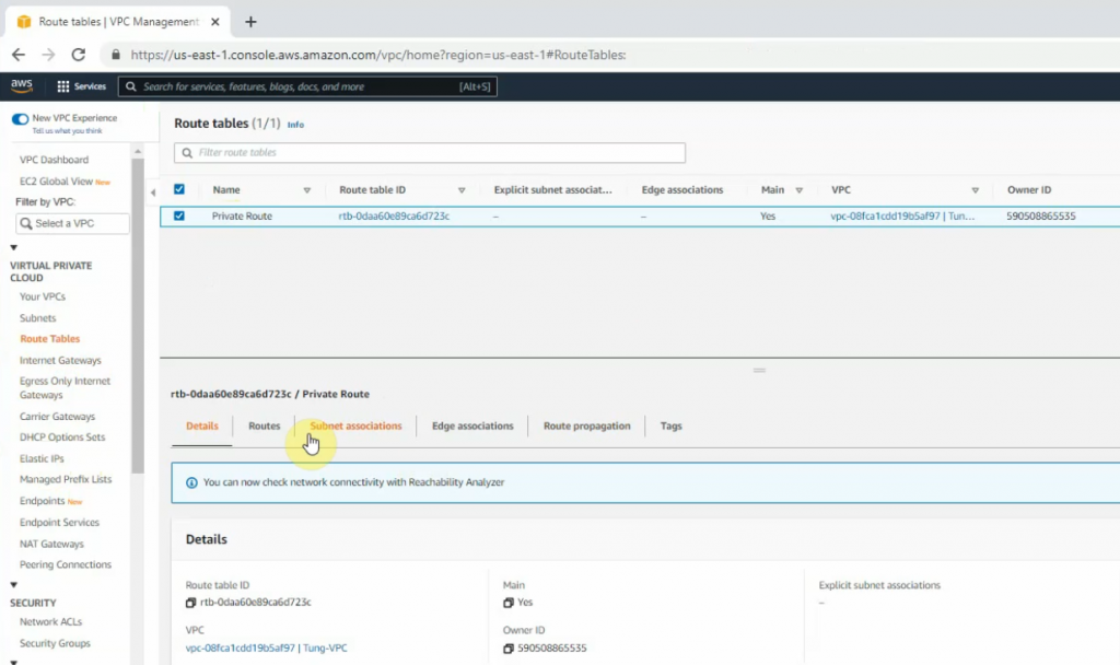
Edit Route table, change default Route table to Private Route.
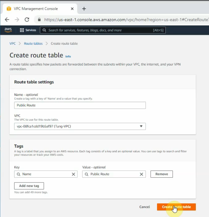
Create a Public Route Table.
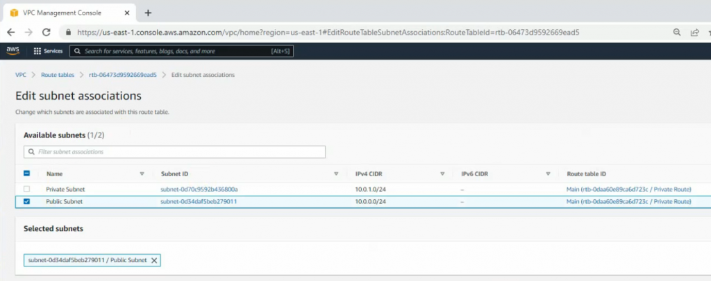
Link the Public Subnet to the Public Route.
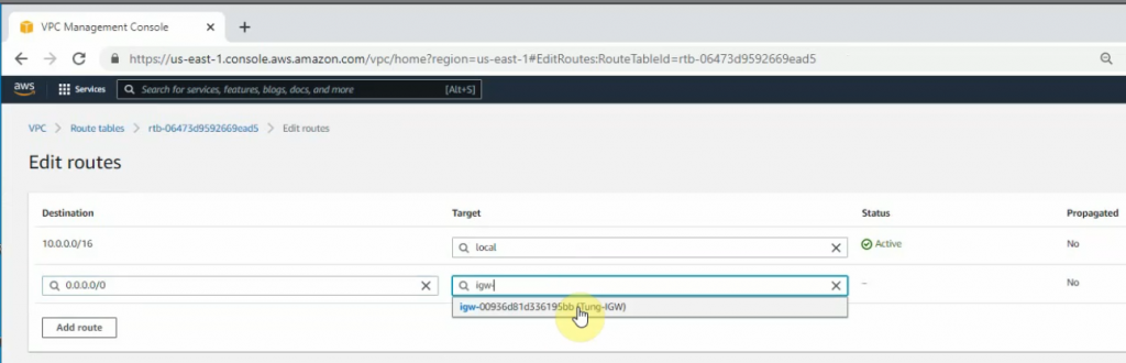
Add a new route 0.0.0.0/0 to your Internet gateway.
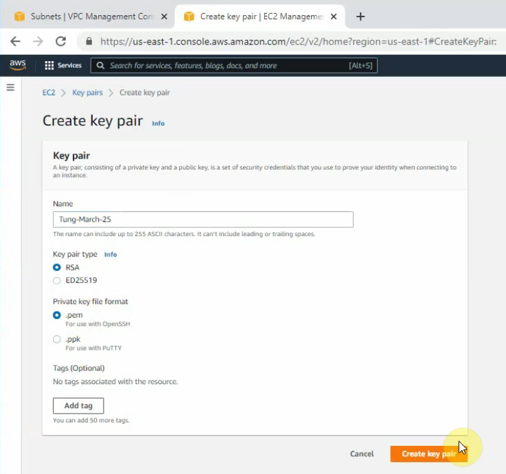
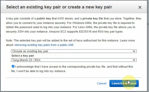
Create a new key pair.
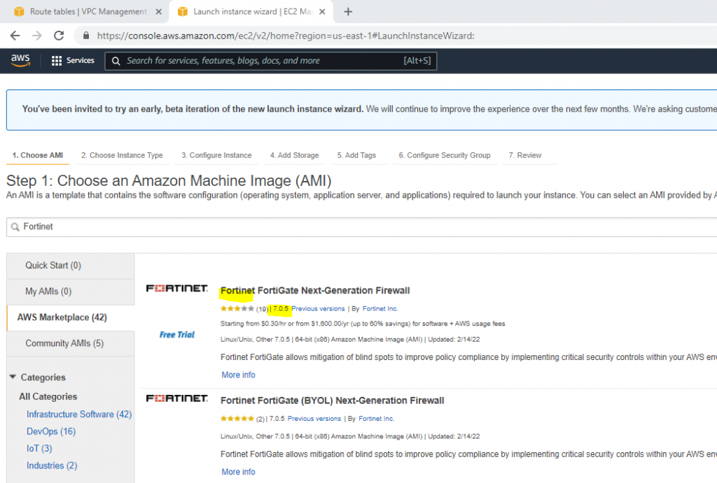
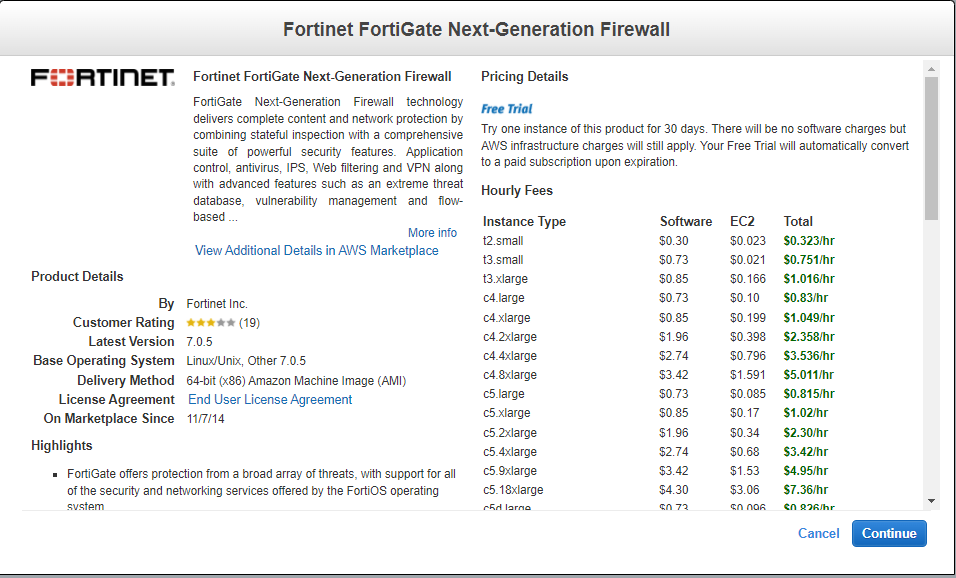
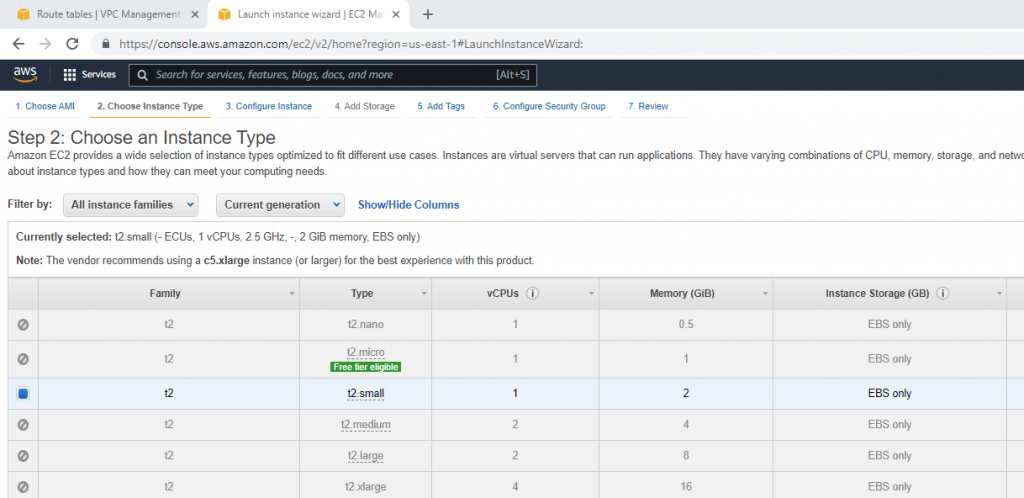
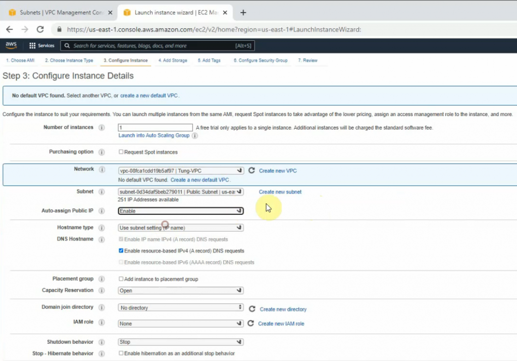
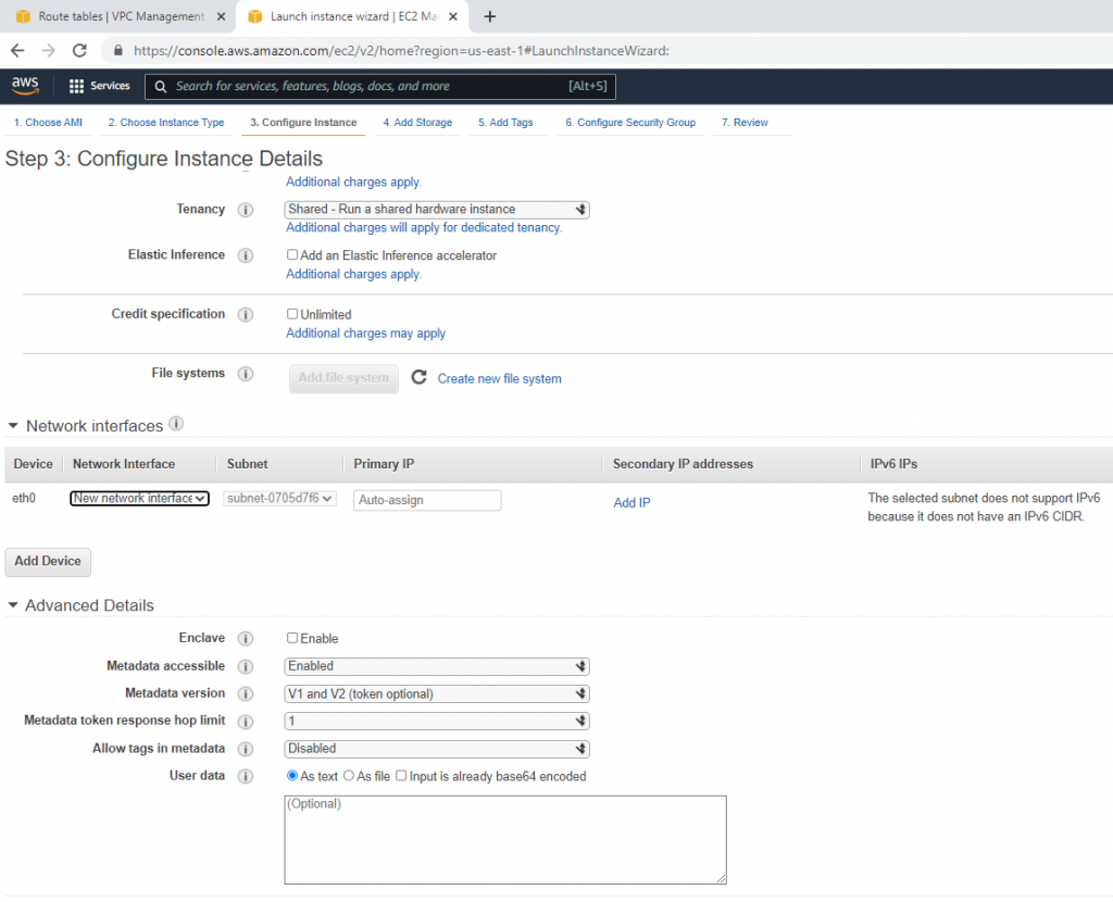
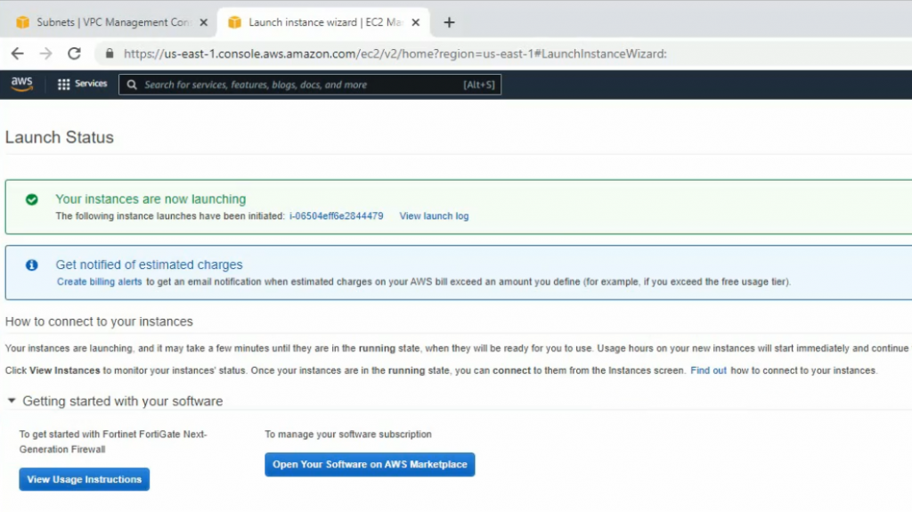
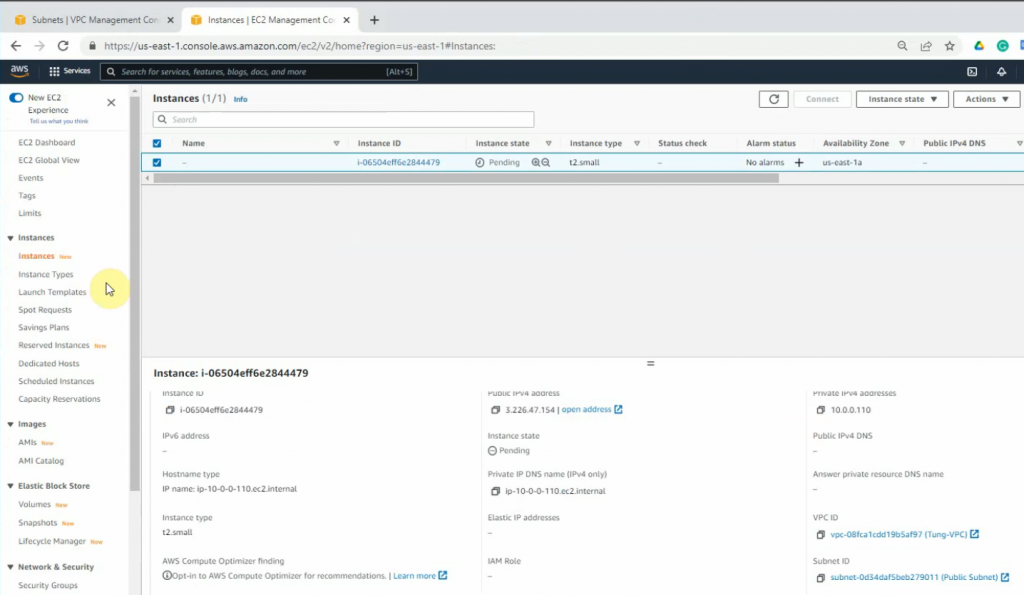
+ Go to EC2, and deploy Fortinet on AWS.
Select your VPC, the subnet belongs to Lab Public Subnet. Also, changing the Auto-assign Public IP is Enable.
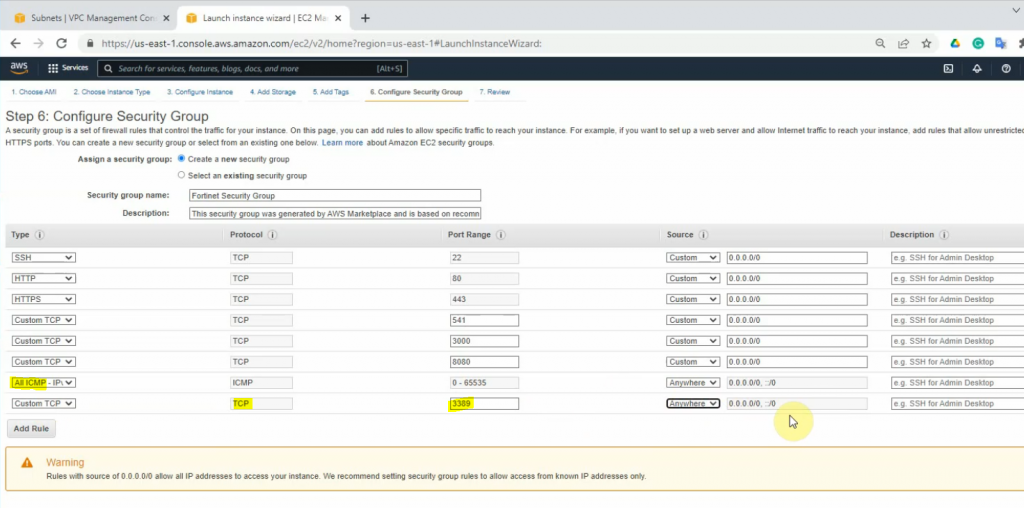
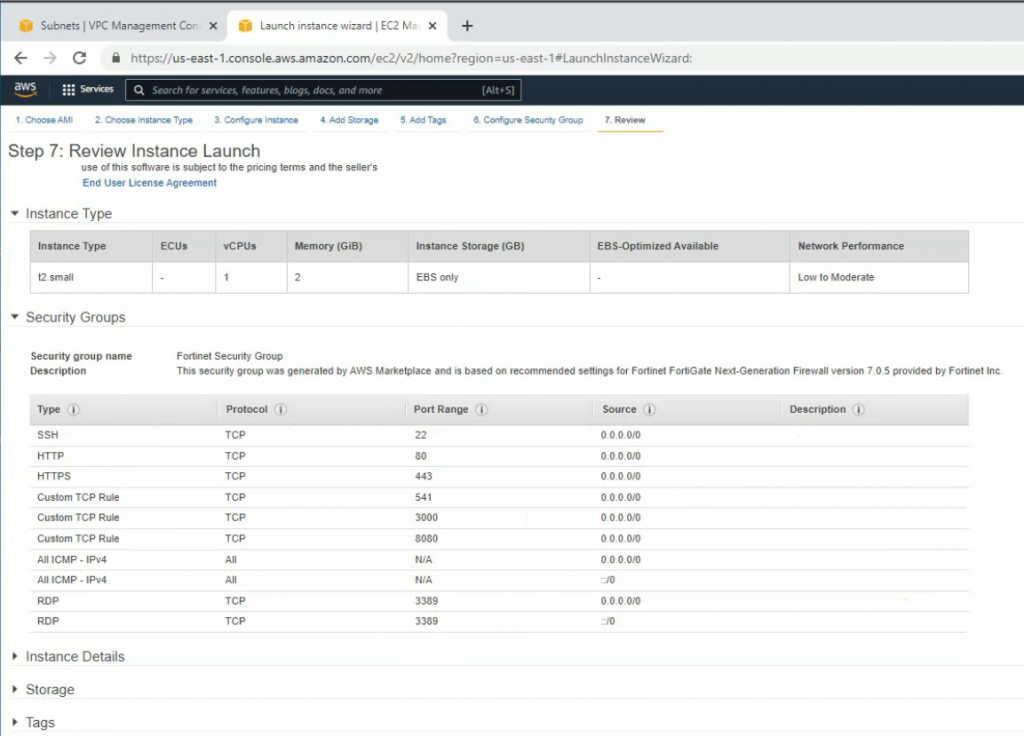
On the Security Group tab, add new two lines at the end of Security Group as a screenshot below. This allows to ping and RDP to the Windows 2016 machine on a private subnet later on.
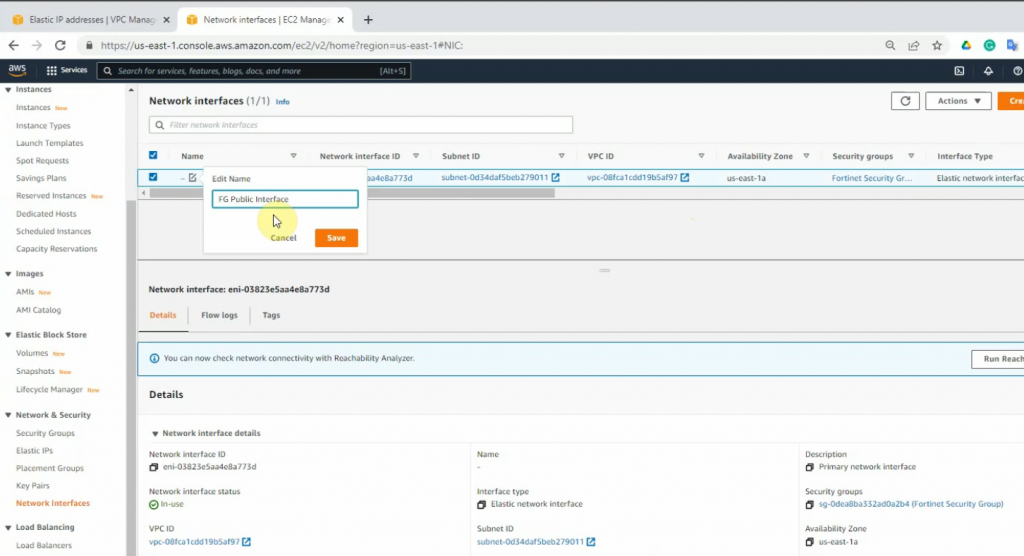
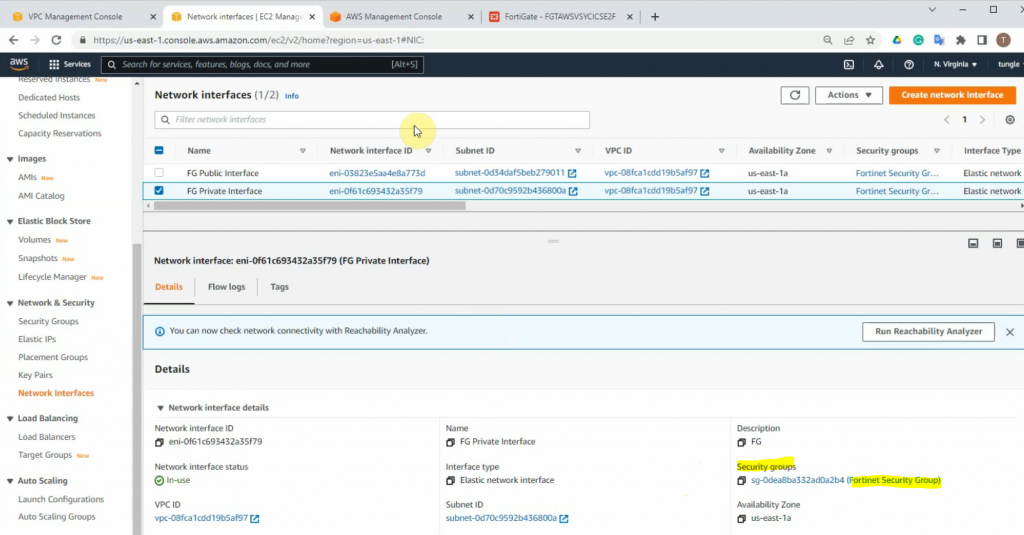
Go to Network interfaces, change the interface to FG Public Interface.
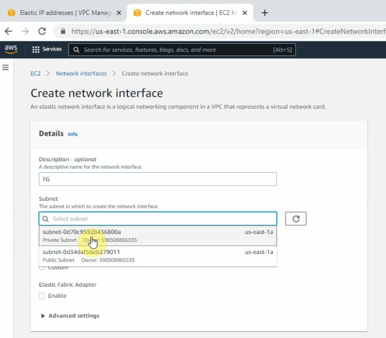
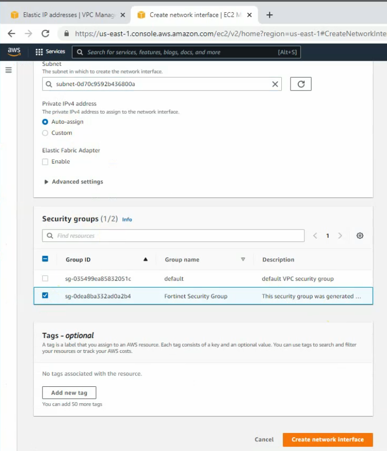
Create a new FG Private interface. Links to the private subnet and FortiGate Security Group.
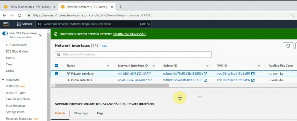
Change to FG Private Interface.
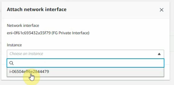
Select the FG private interface, choose Action on the top right-hand side and Attach this network interface to Fortinet EC2.
Right-click on both FG Public and Private interfaces, and disable “Change source/dest check” on both interfaces to allow NAT traffic on these interfaces.
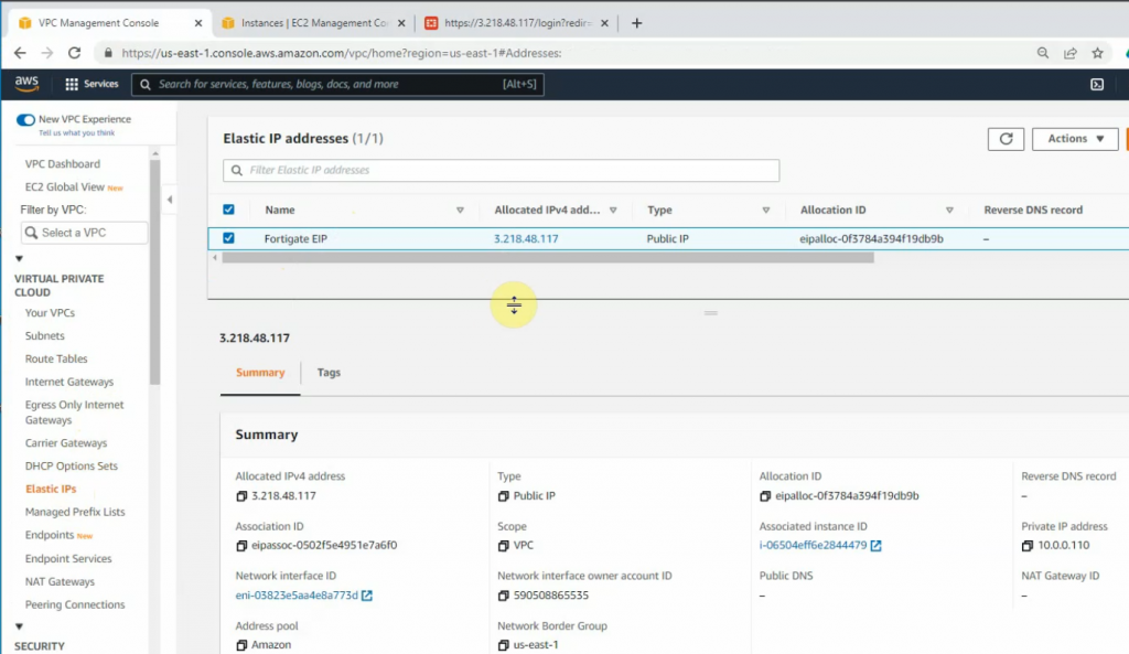
Create a new Elastic IP address.
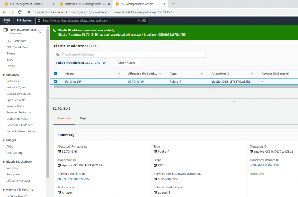
Change to Fortinet EIP.
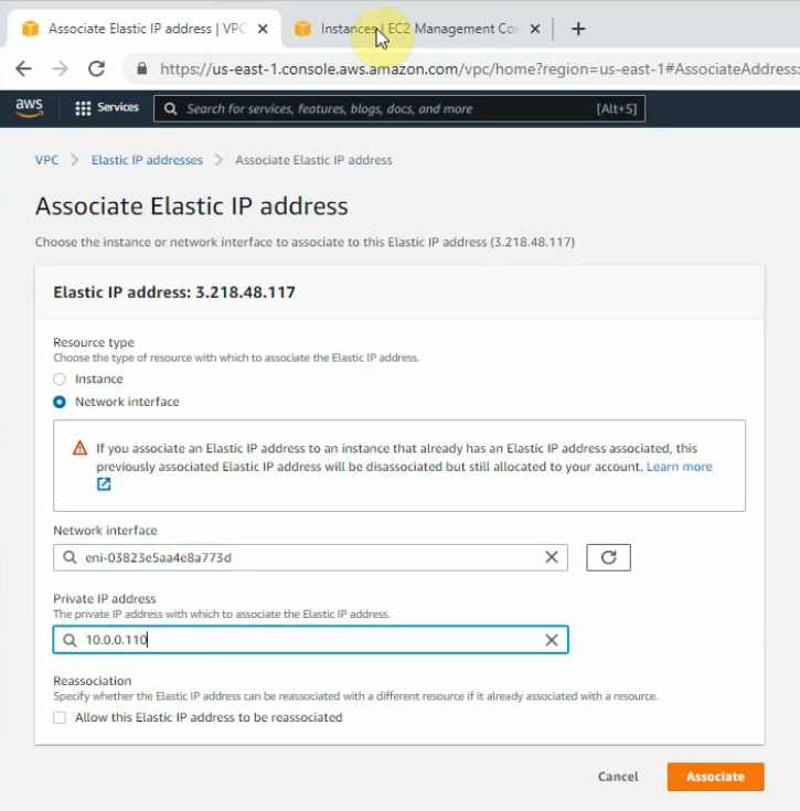
Associate this Elastic IP address to Fortinet EC2.
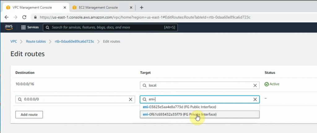
Back to Route tables, add a new route 0.0.0.0/0 to FG private interface.
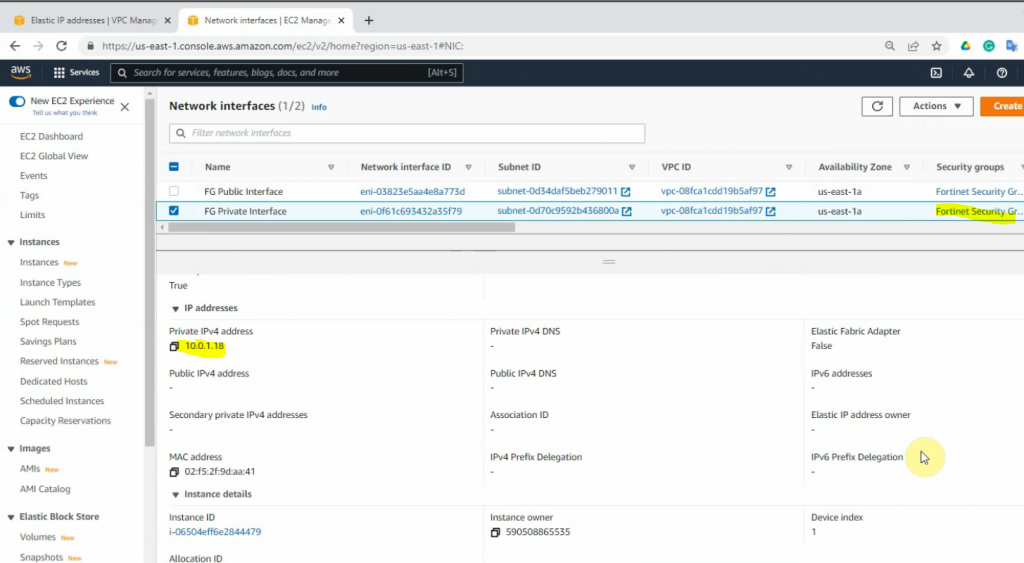
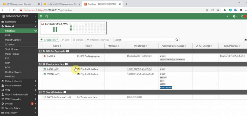
Now, Fortinet has two interfaces. One is Private, and another one is Public.
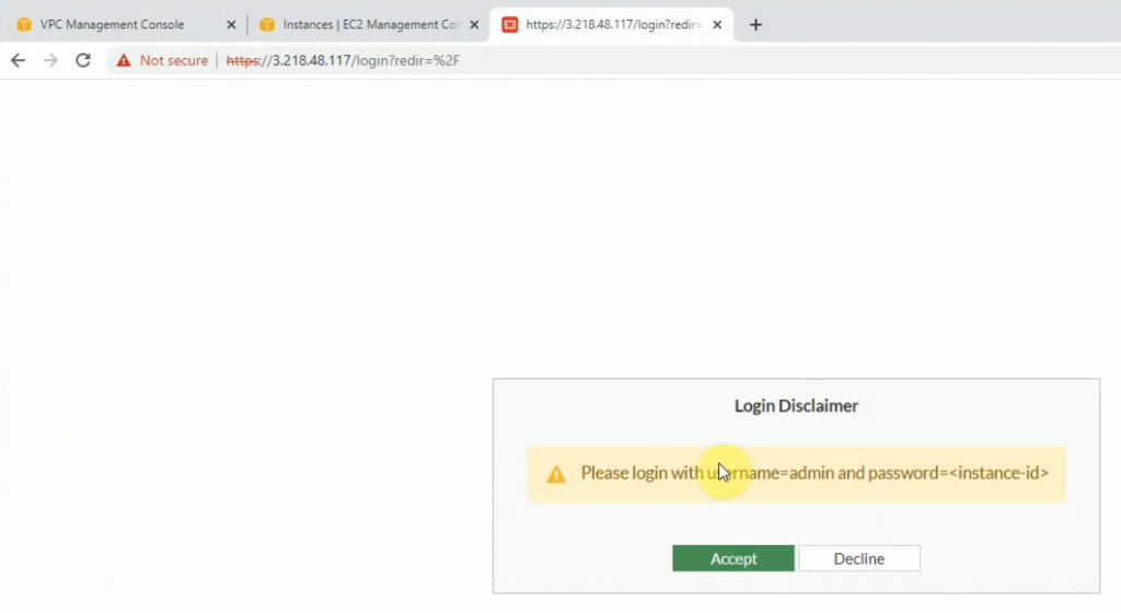
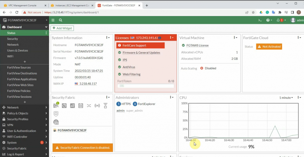
Copy the Elastic IP address and paste it to your web browser to access the FortiGate management interface.
Access Fortinet via the Internet.
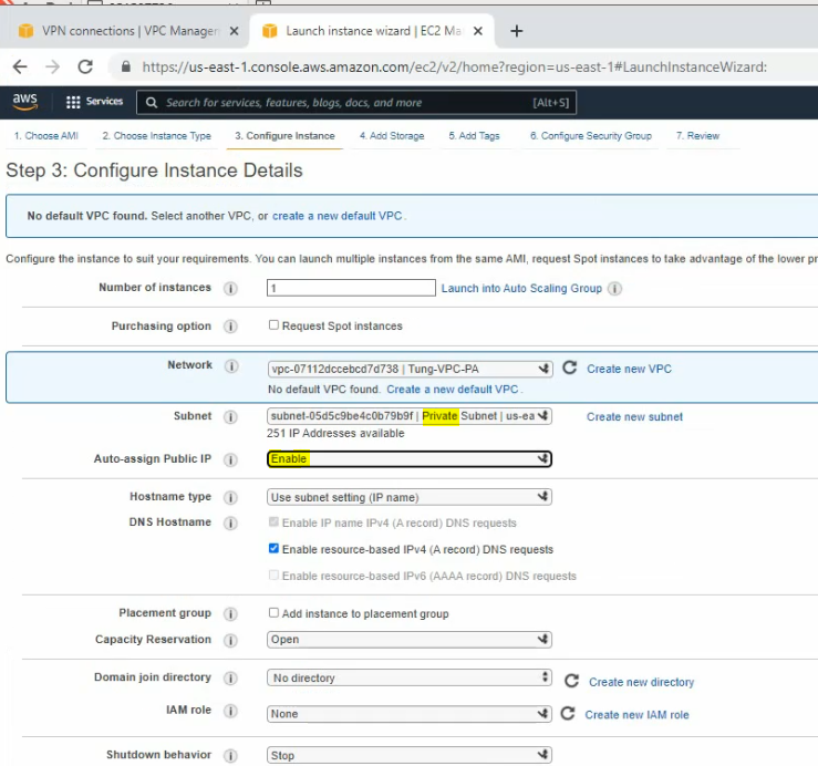
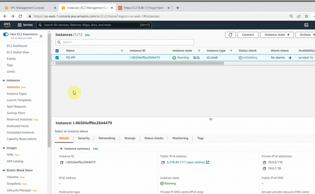
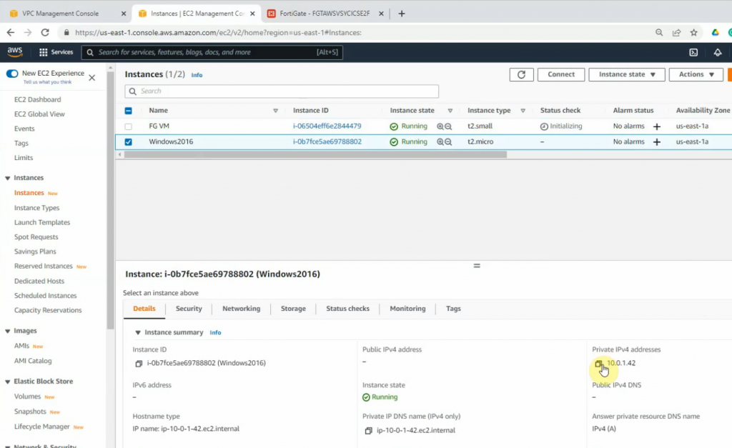
+ Launch a new Windows VM EC2 instance on your VPC.
Network: Your VPC
Subnet: Private subnet
Auto-assign Public IP: Disabled. We will access RDP to the machine via DNAT on FortiGate.
On the Security Group setting, add two lines to allow RDP and ICMP traffic to the machine.
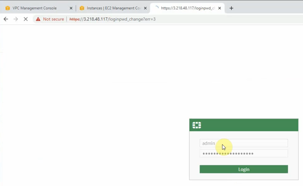
+ Login to Fortinet.
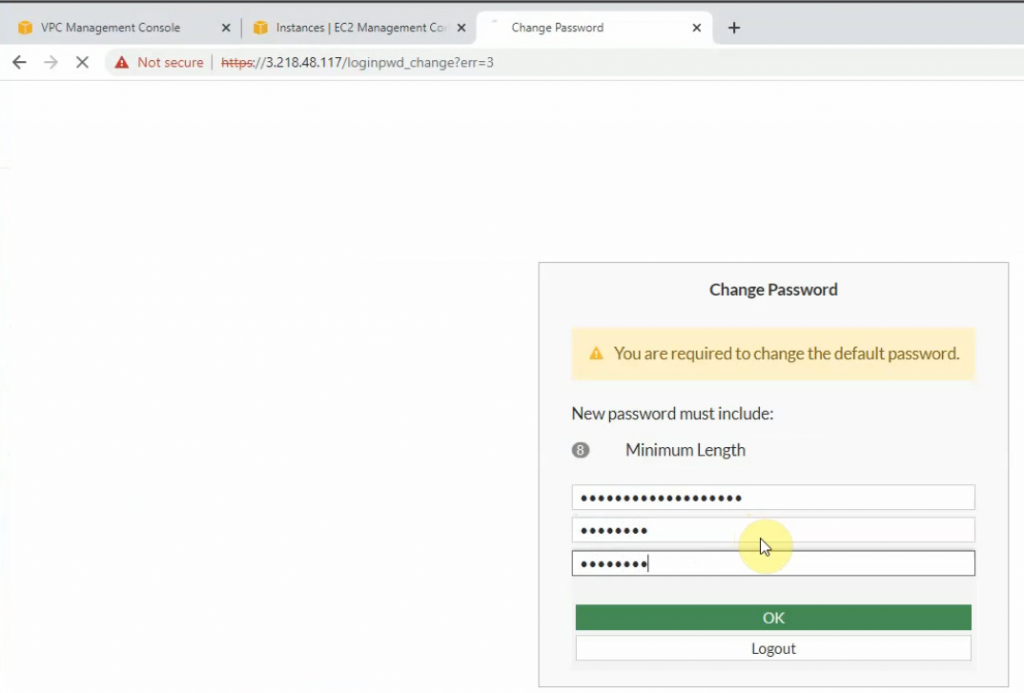
Copy the FG instance and paste it to password login.
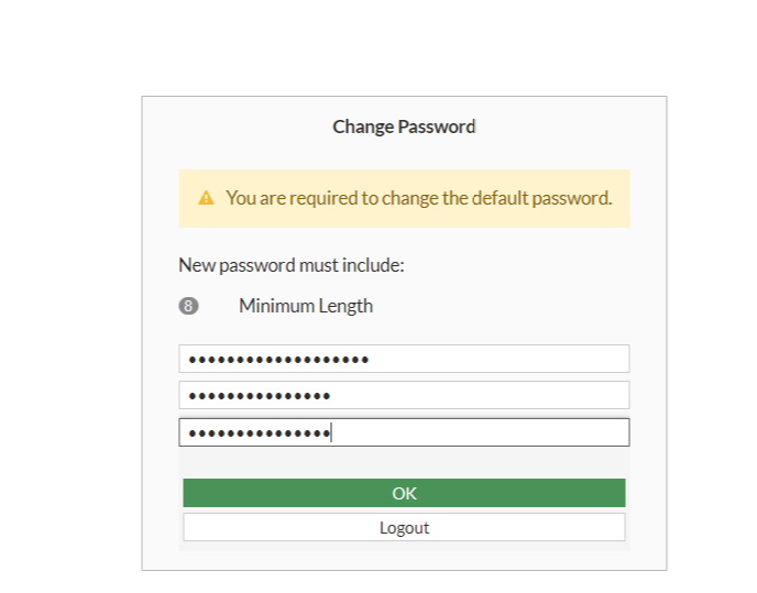
Change the password to login to Fortinet.
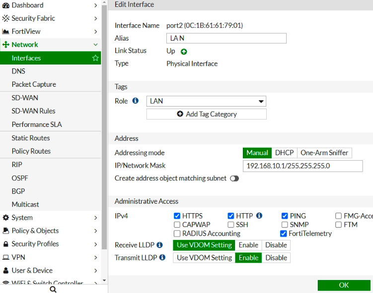
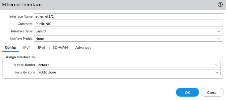
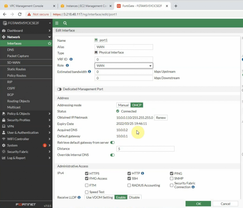
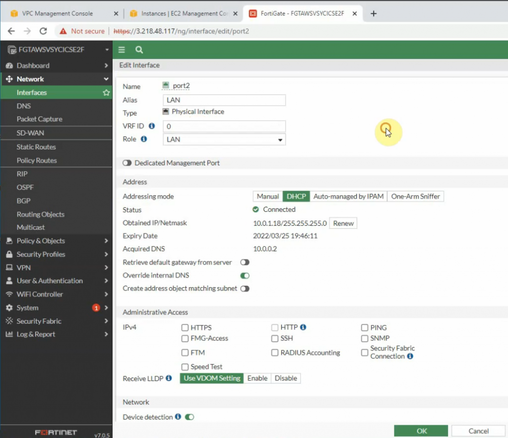
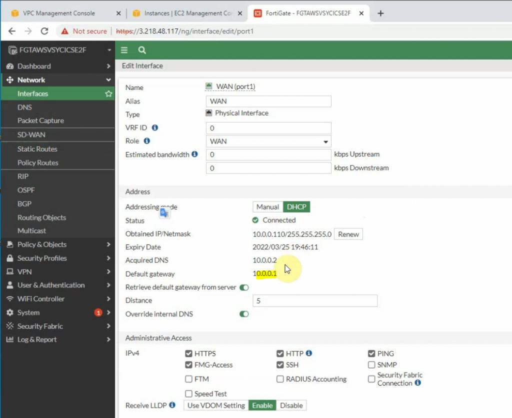
Edit WAN and LAN interface setting.
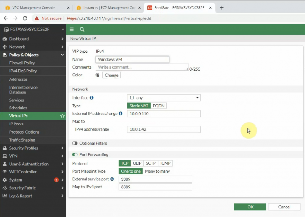
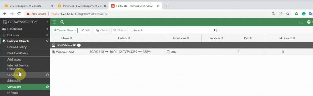
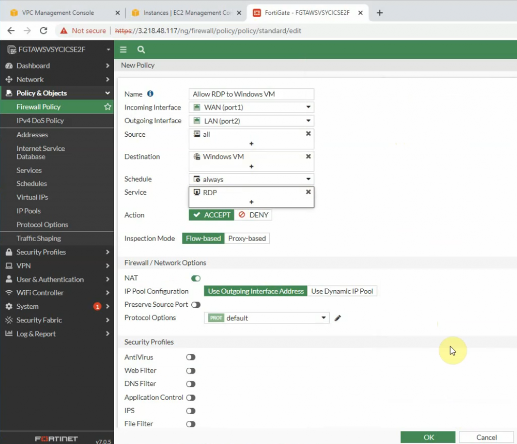
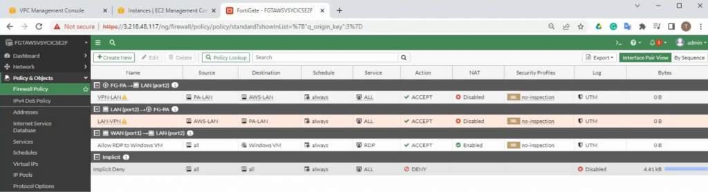
Back to Fortinet to configure Firewall Policy to allow RDP traffic from the Internet to the Windows VM machine.
Configure port forwarding to allow traffic from the Internet to Windows 2016 VM instance on AWS.
External IP address: IP address of FG on the public subnet
Map to IPv4 address on the private subnet is IP address of Windows VM computer.
The external service port and map to IPv4 port is 3389.
Allow inbound traffic from WAN to this machine.
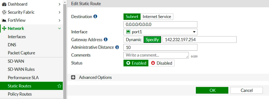
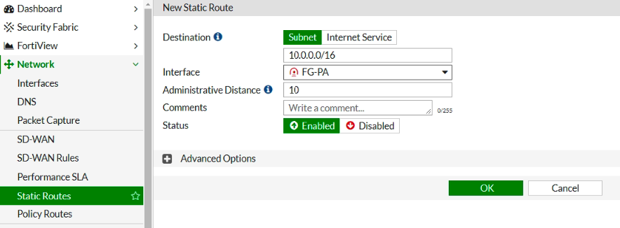
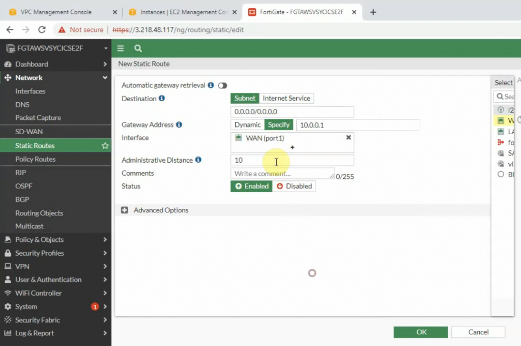
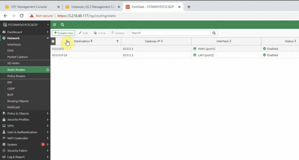
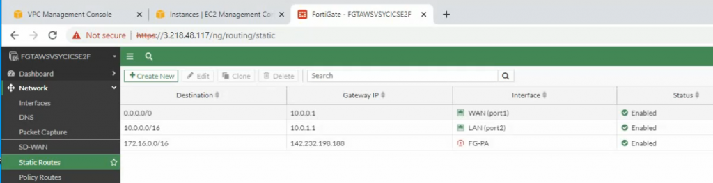
Create both static routes to allow a private subnet to access outside.
Creating new static routes for the private subnet from 10.0.0.0/16 to 10.0.1.1 that is the default gateway on the private subnet.
Try to access the machine.
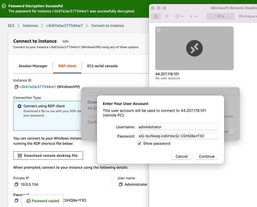
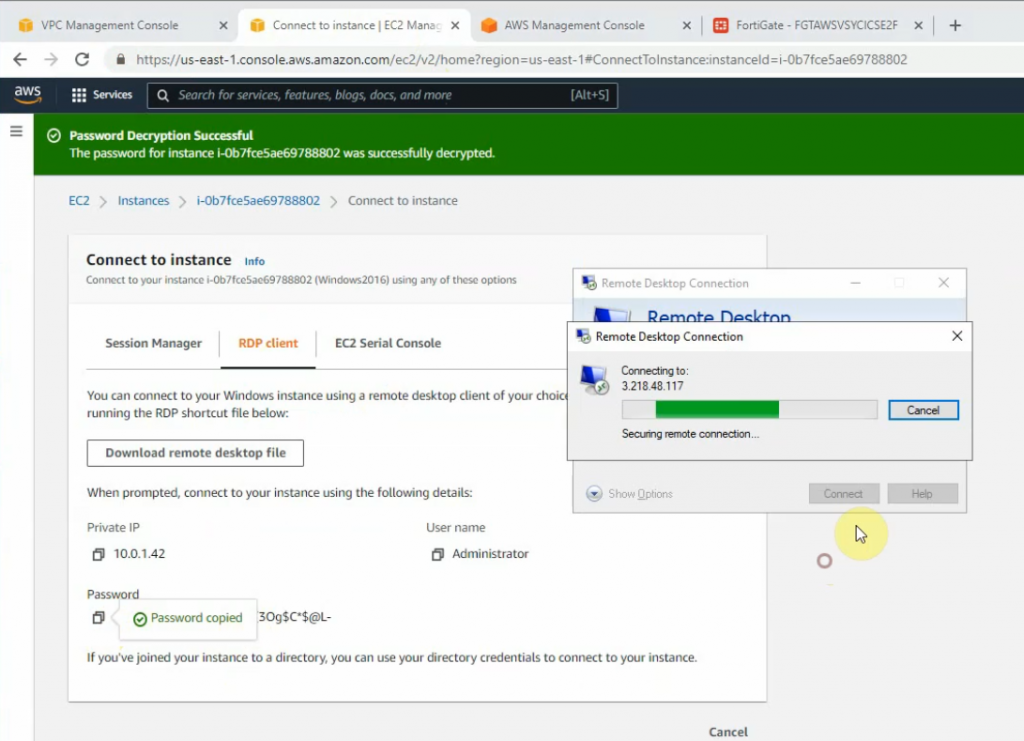
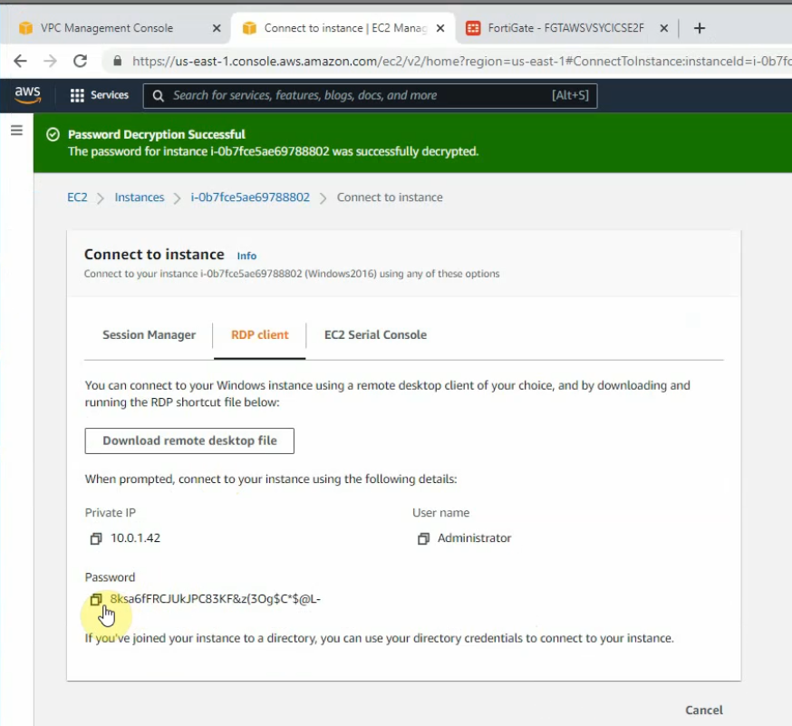
Load private key to decrypt Windows password.
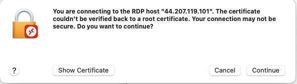
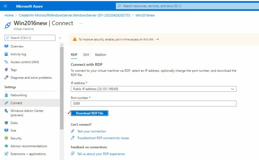
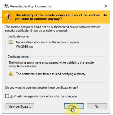
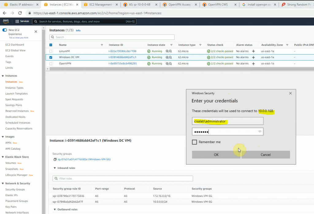
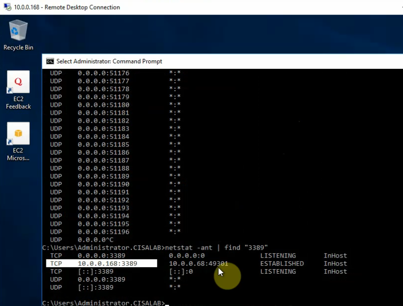
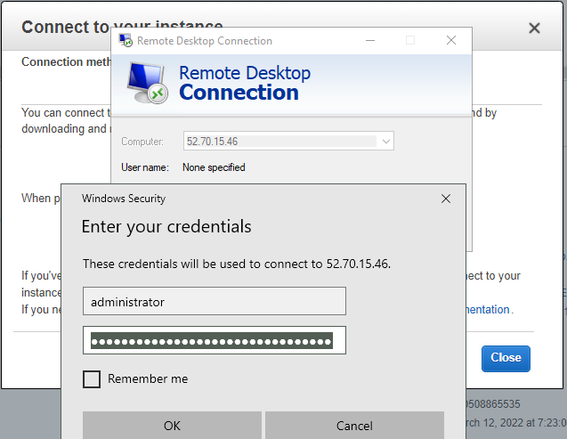
Access RDP to Windows 2016 instance on AWS.
Now we can see the RDP traffic via Fortinet.
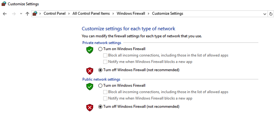
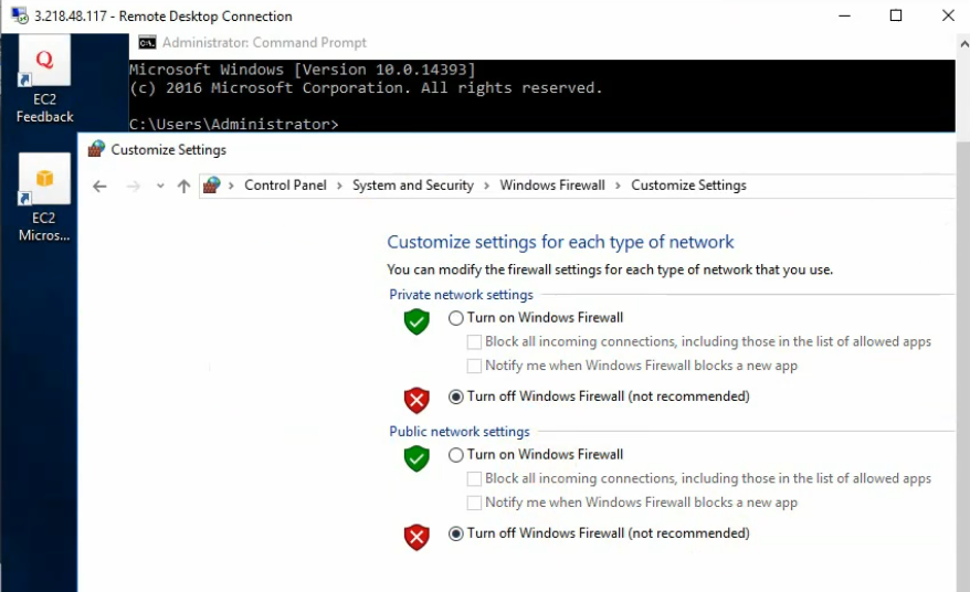
Disable Windows Firewall to allow ICMP traffic to that machine on Palo Alto private subnet.
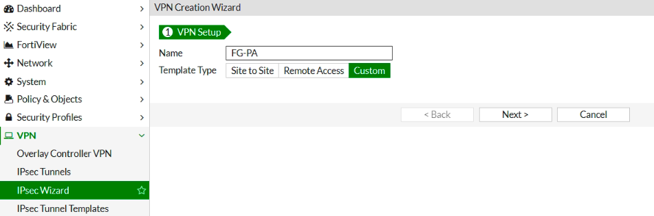
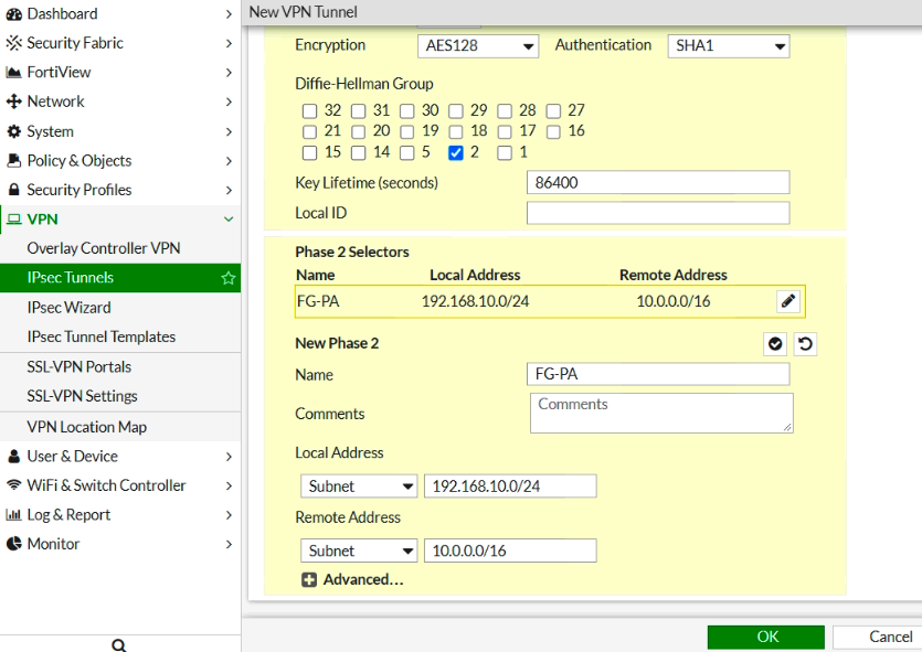
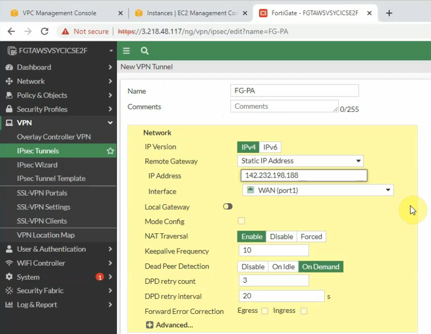
Configure IPSEC site to site wizard. Choose Custom.
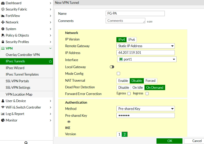
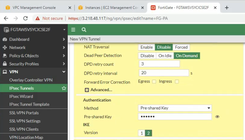
Enter IP address of public interface of PA. Disable NAT traversal, enter the pre-shared key and choose the IKE v2.
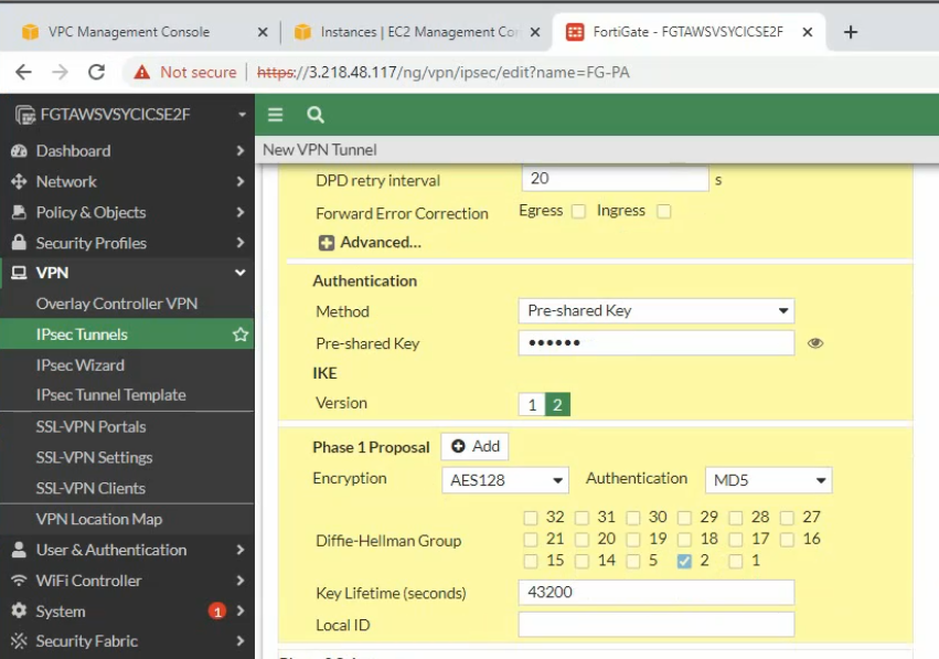
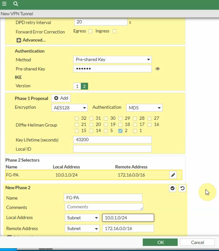
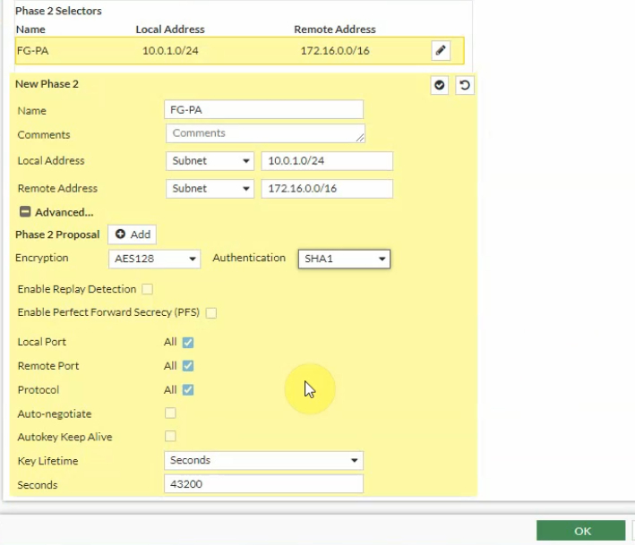
Phase 1 and Phase 2 settings need to match with the Palo Alto setting.
Local Address: the private subnet of FG: 10.0.1.0/24
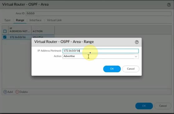
Remote Address: PA LAN subnets: 172.16.0.0/16
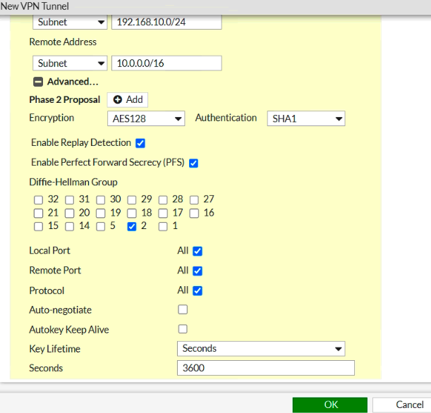
Click the Advanced tab. Change the setting to match with PA Phase 2 setting
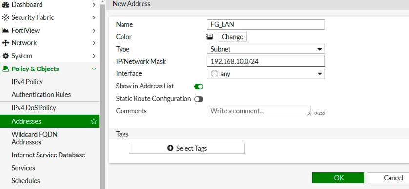
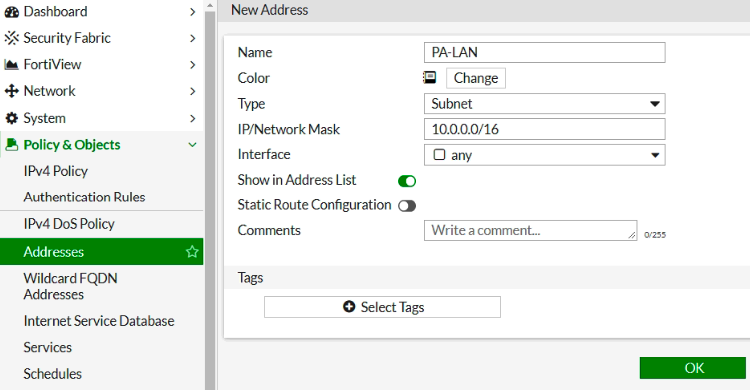
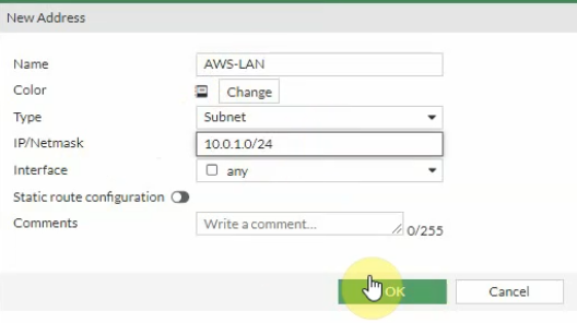
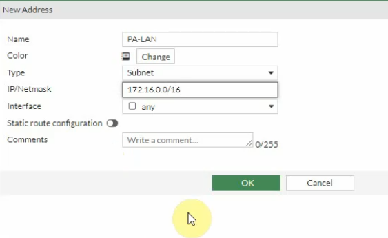
Create Fortinet LAN and PA LAN subnet network addresses.
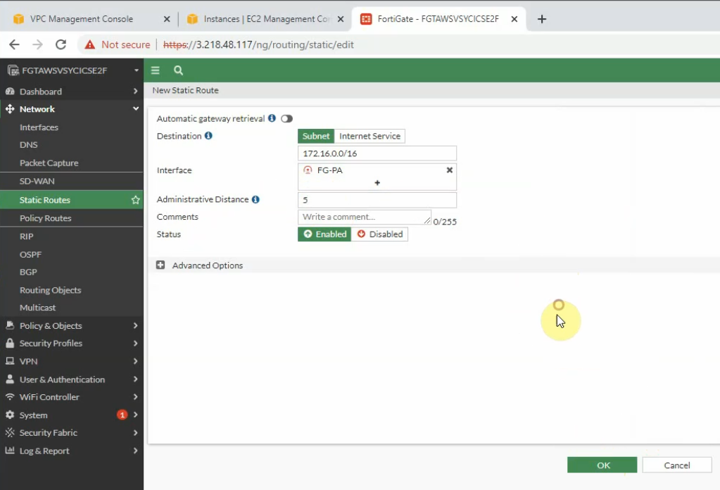
Create a static route on Fortinet to allow private subnet traffic to the Palo Alto LAN subnet.
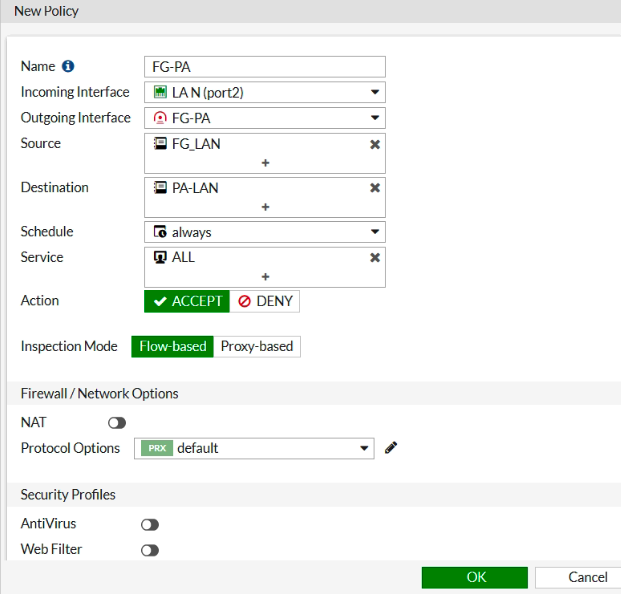
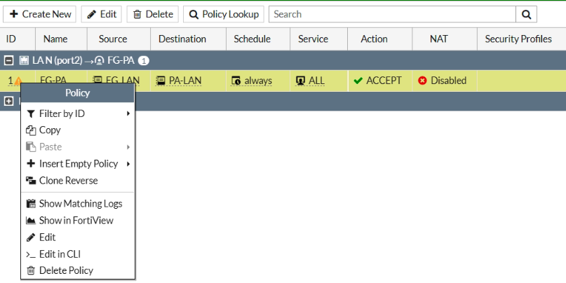
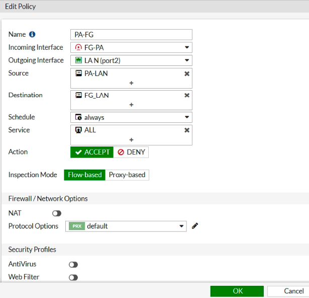
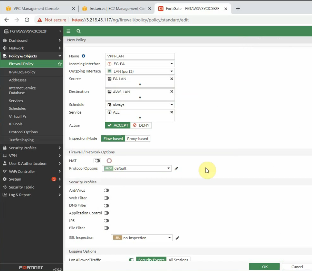
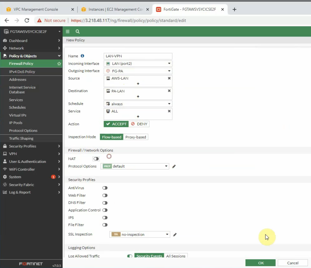
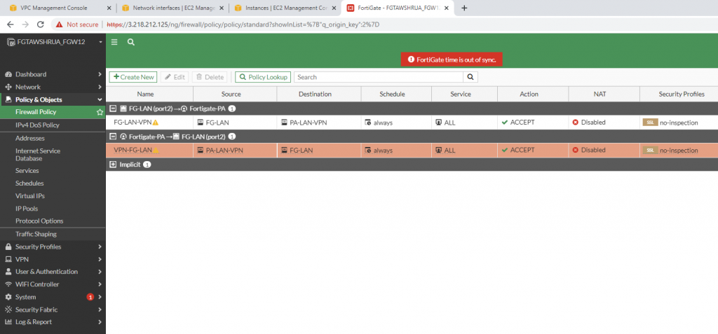
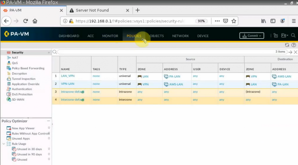
Create a Security Policy to allow traffic from the Fortinet LAN subnet to the PA LAN subnet. Remember to uncheck NAT setting on access rules from AWS LAN to PA LAN and vice versa.
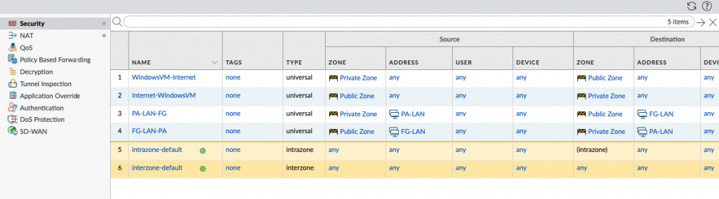
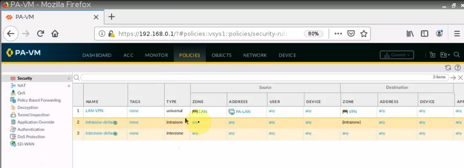
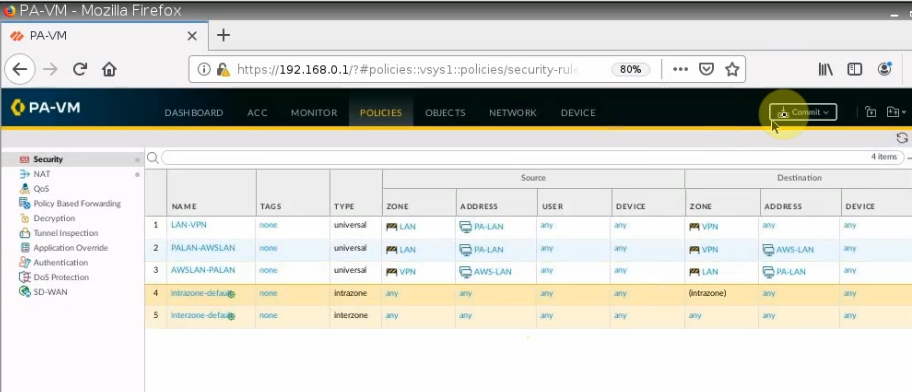
PA LAN subnet to AWS LAN subnet.
AWS LAN subnet to PA LAN subnet.
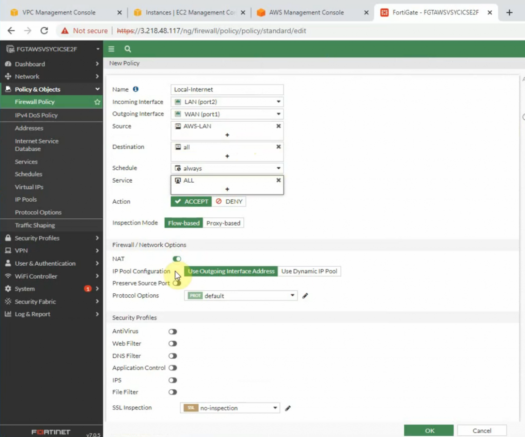
Create a new access rule to allow the FG LAN subnet to access the Internet.
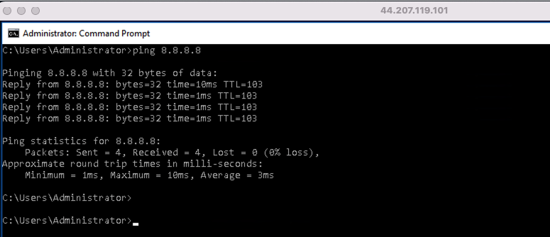
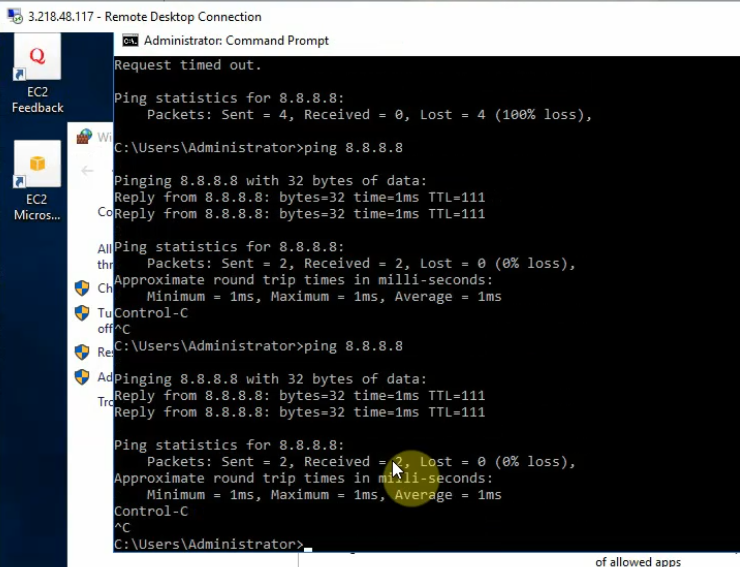
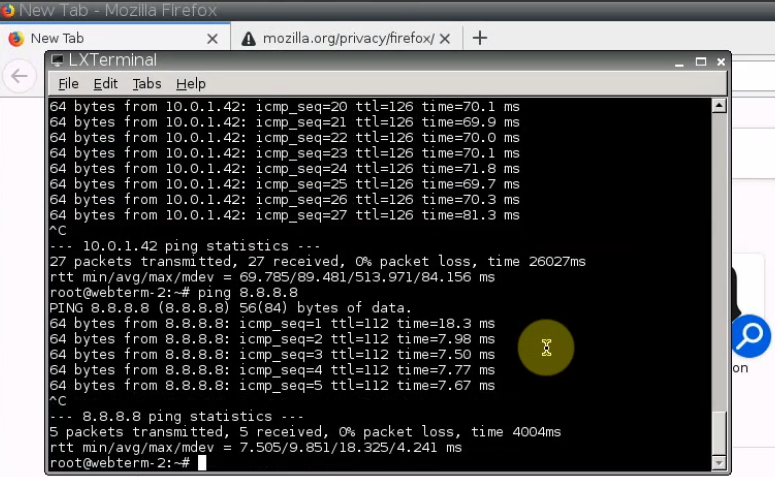
Ping 8.8.8.8 from Windows 2016 VM instance.
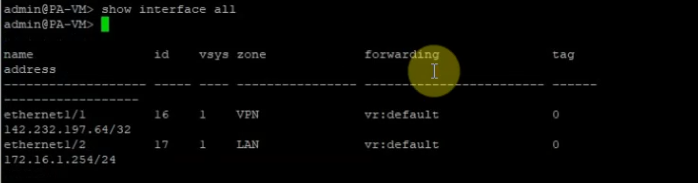
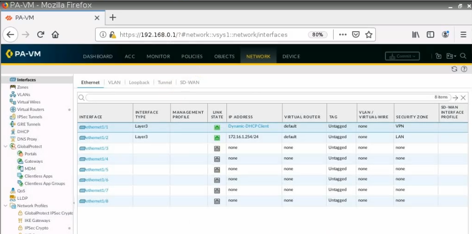
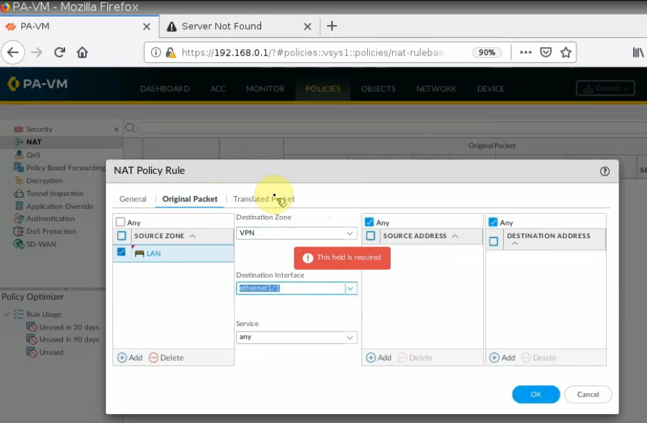
+ Configure PA.
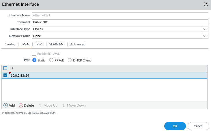
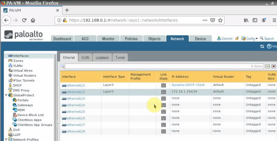
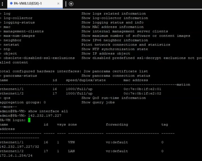
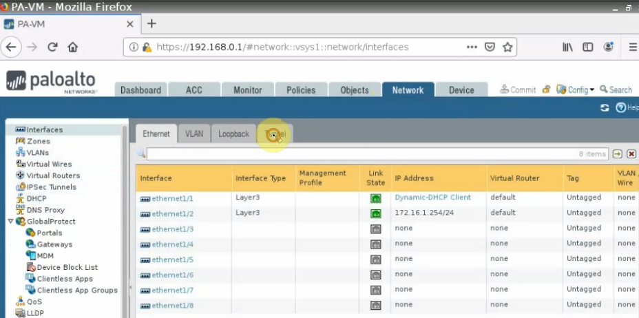
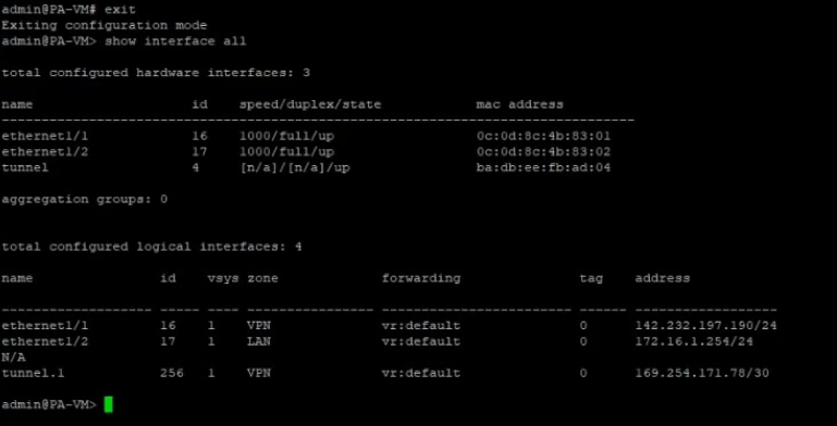
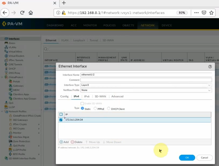
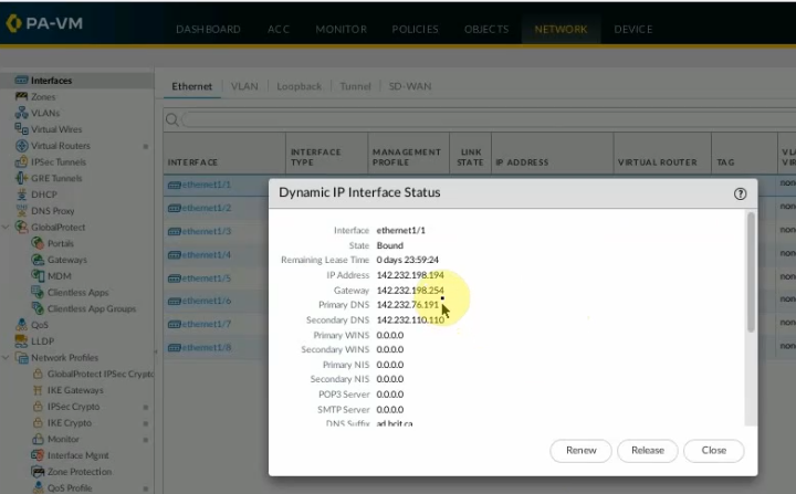
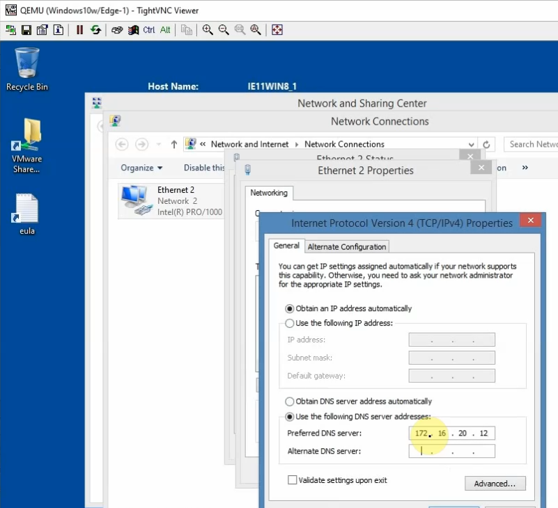
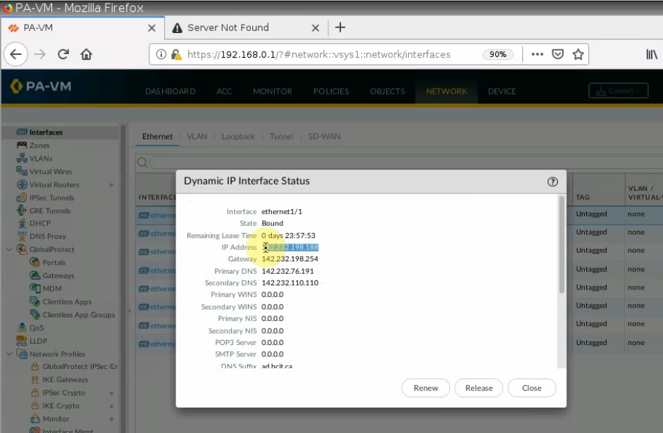
Setting the IP address for e1/1 is DHCP, and assign an IP address for e1/2 is 172.16.1.254/24
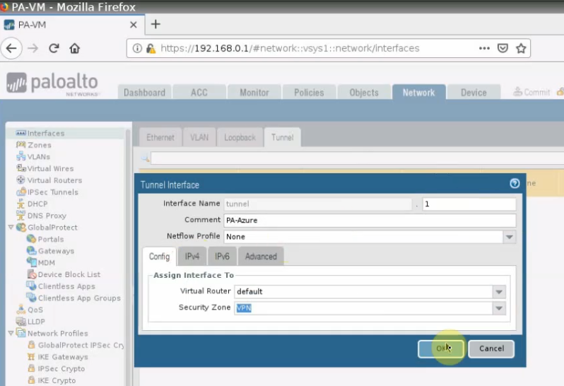
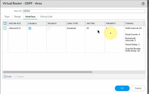
Create a tunnel interface: tunnel 1.
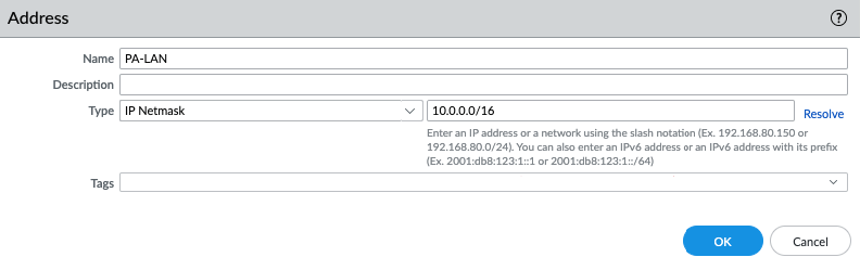
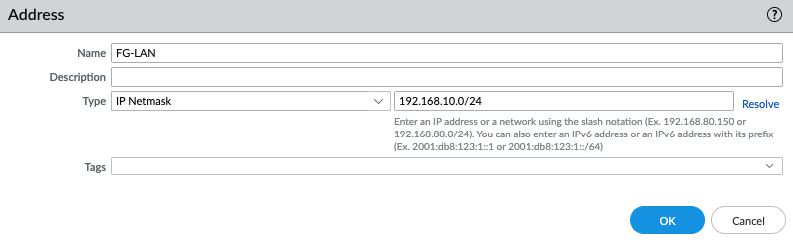
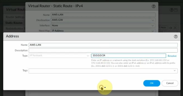
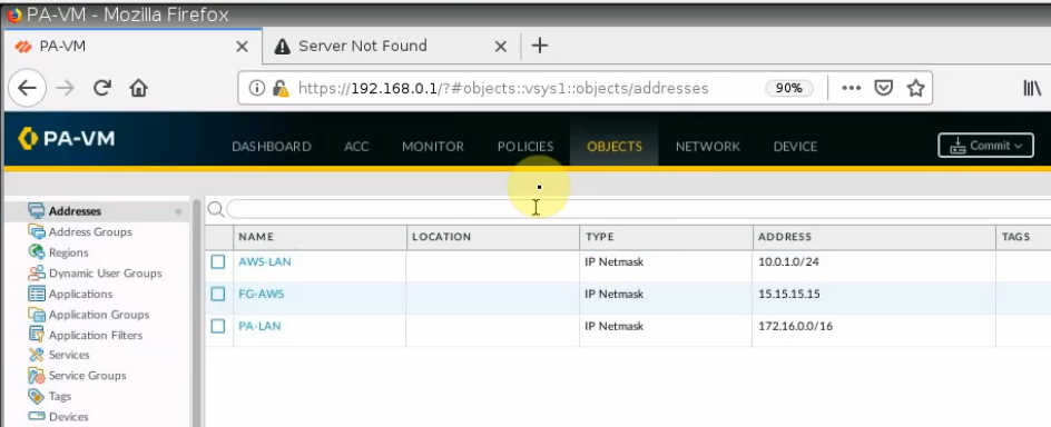
Create network objects for FortiGate, PA LAN, and AWS LAN.
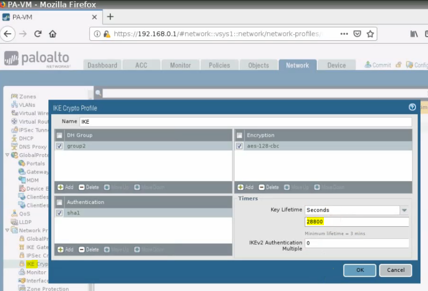
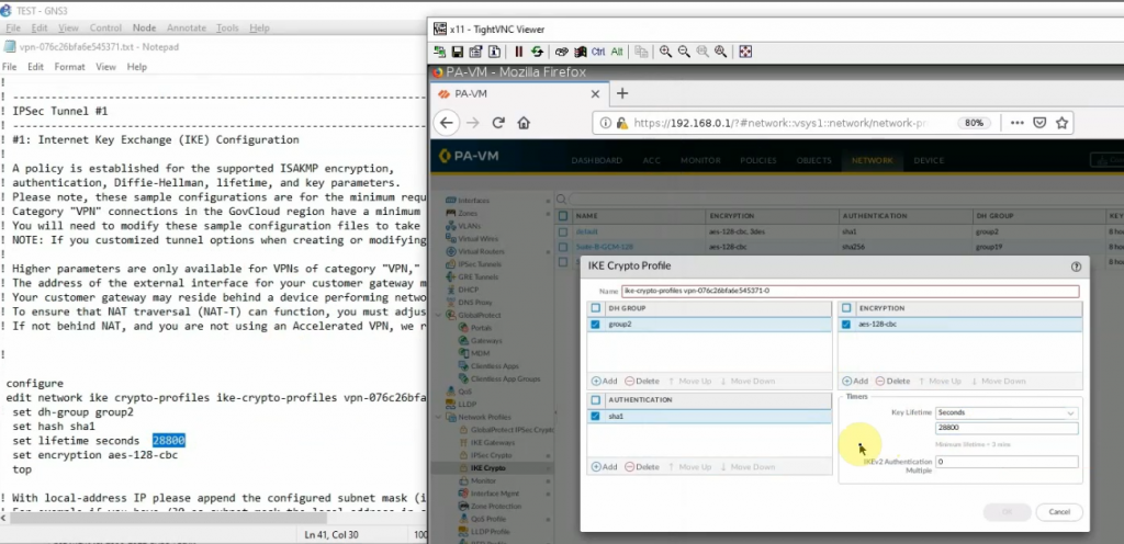
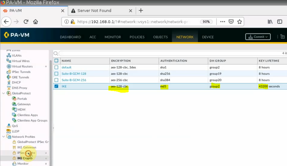
Create IKEC Crypto.
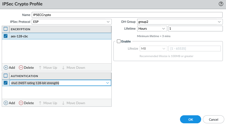
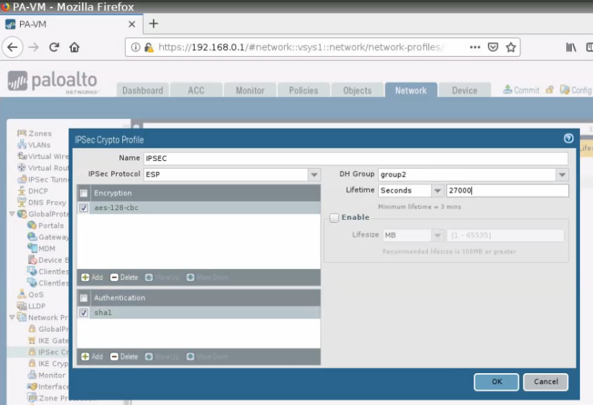
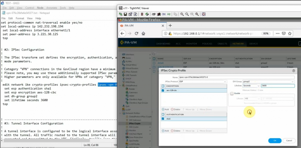
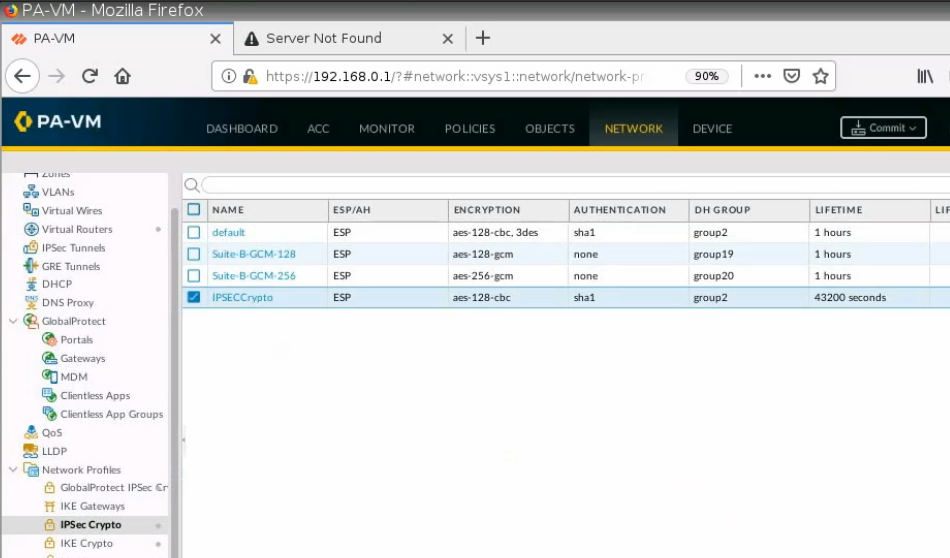
Create an IPSEC Crypto.
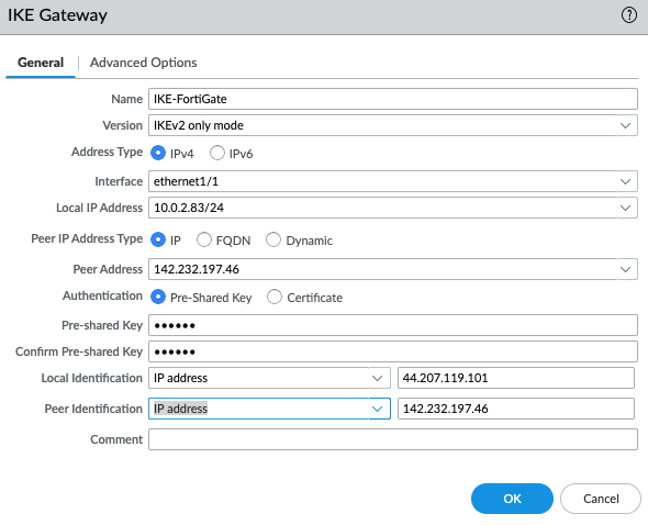
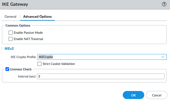
IKE Gateway.
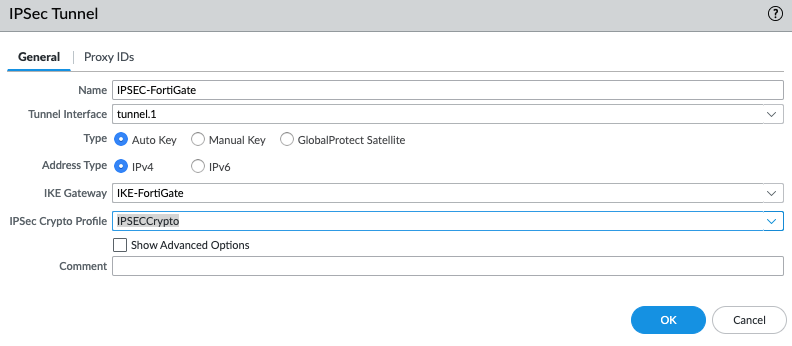
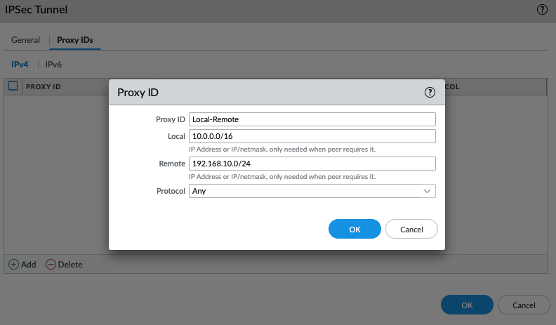
IPSEC tunnel.
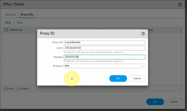
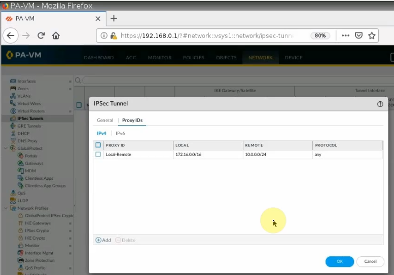
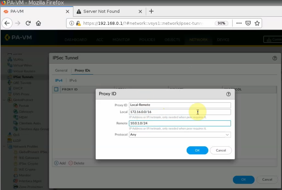
On Proxy ID tab.
Local: PA LAN subnets.
Remote: AWS LAN subnet.
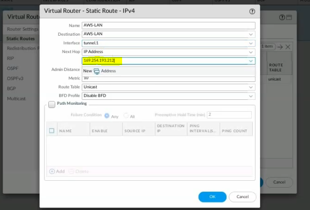
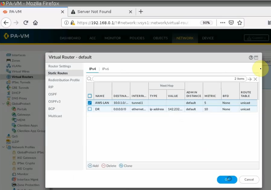
Create a Static Route from PA LAN to Fortinet LAN on AWS.
Create both Security Policies to allow traffic from PA LAN subnet to AWS LAN subnet.
Remember to click “Commit” button to apply the new settings on PA.
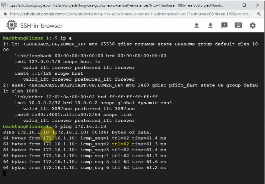
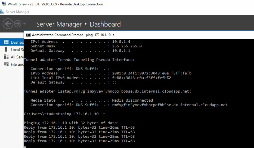
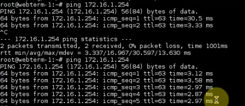
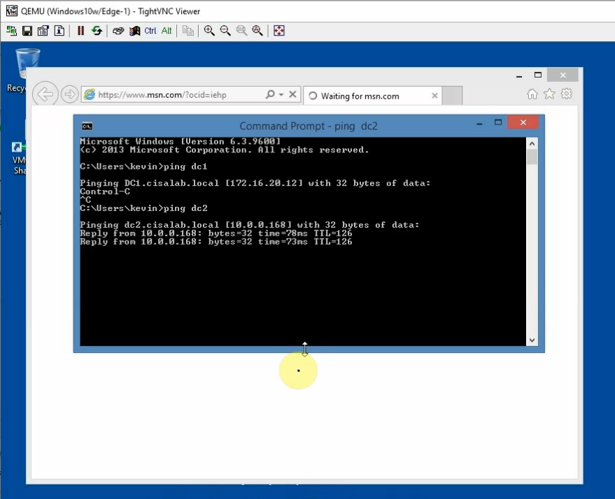
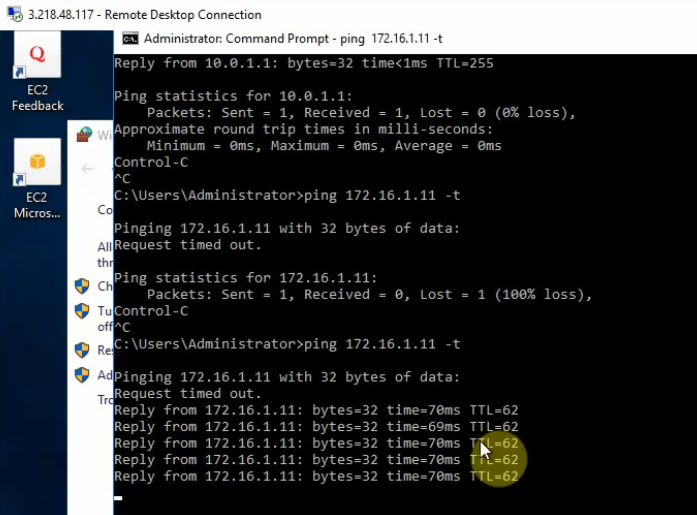
From Windows 2016 VM instance, pings a machine on PA LAN subnet.
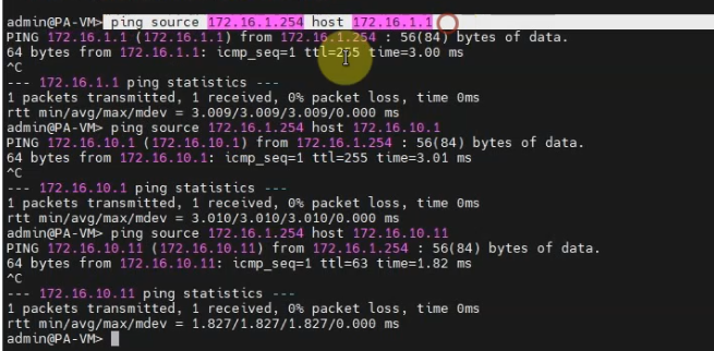
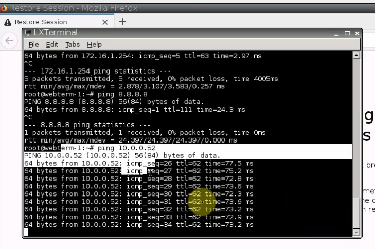
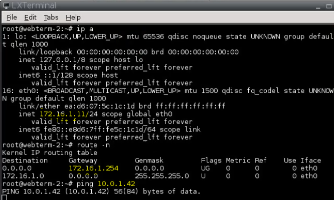
+ Pings from PA LAN subnet to AWS LAN subnet.
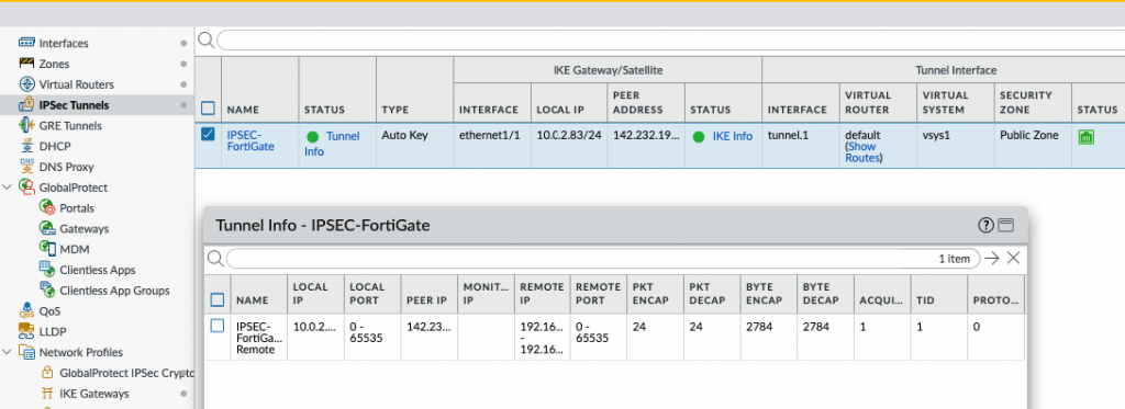
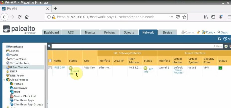
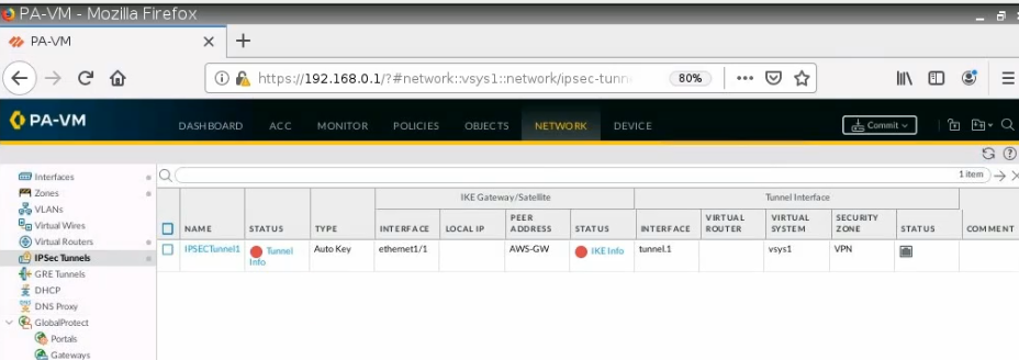
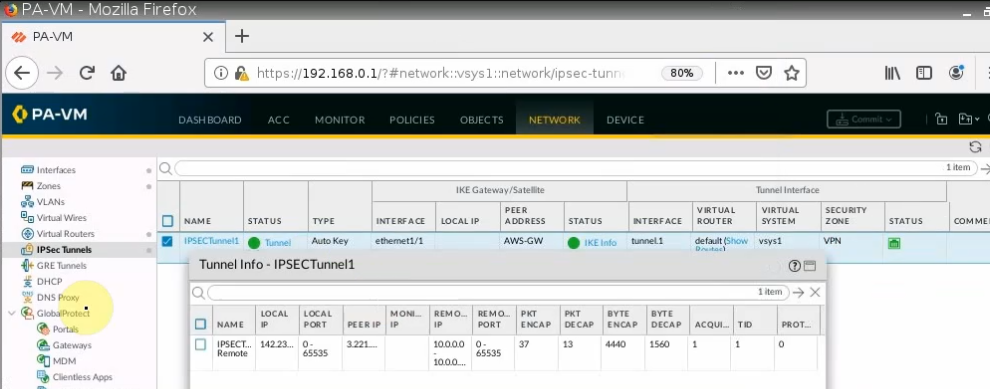
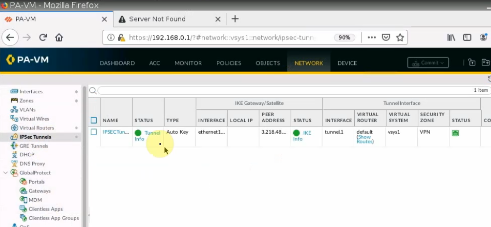
On PA, a tunnel is up.
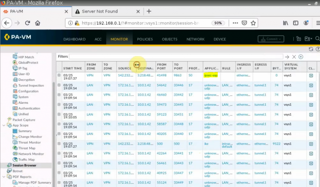
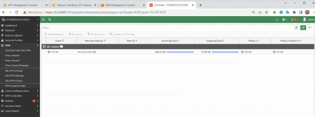
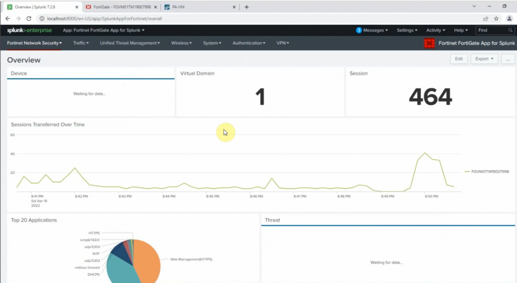
Monitoring to see the traffic on both sites.
On FortiGate.
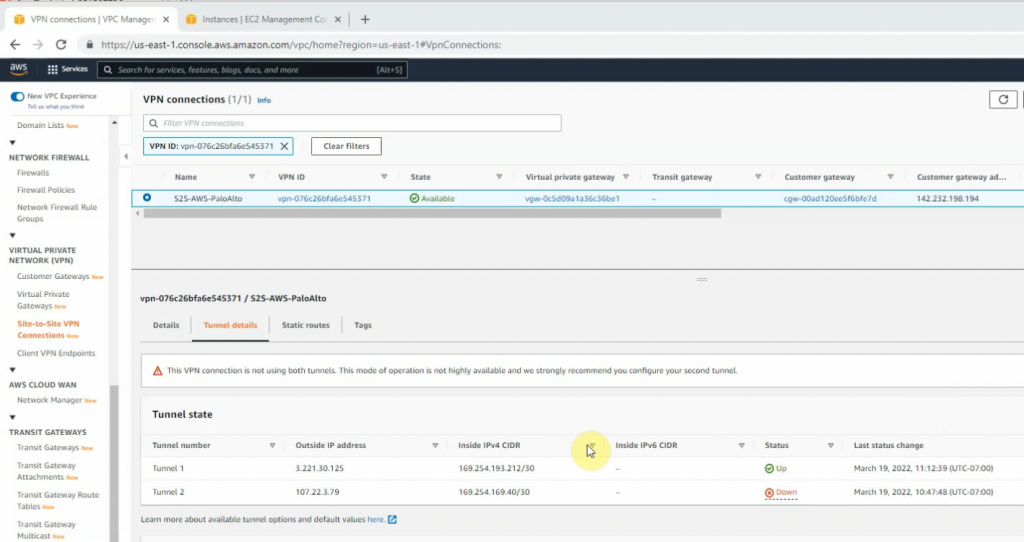
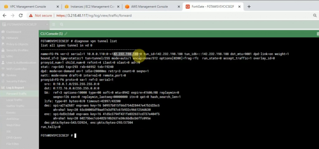
An IPSEC VPN site-to-site tunnel is up.
diagnose vpn tunnel list
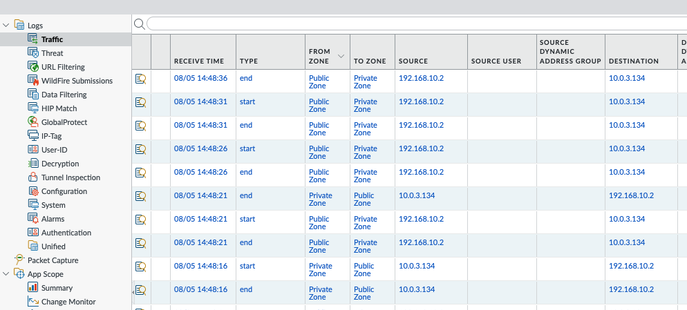
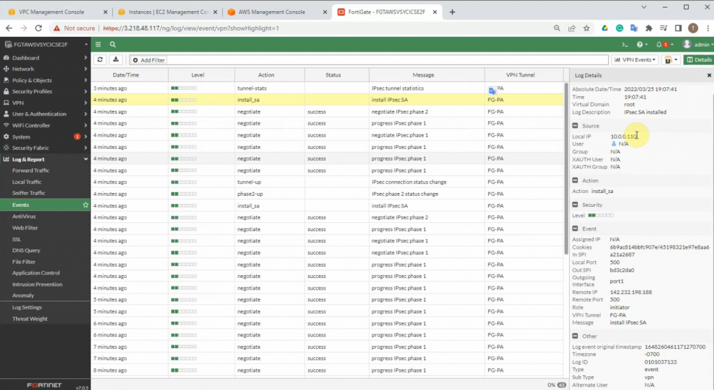
Click on the log and Report to see events that are related to VPN.
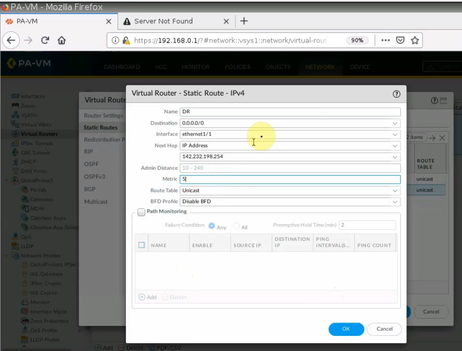
+ Back to PA to create another static route to allow the PA LAN subnet to access the Internet.
A next hop is the default gateway of the PA public subnet.
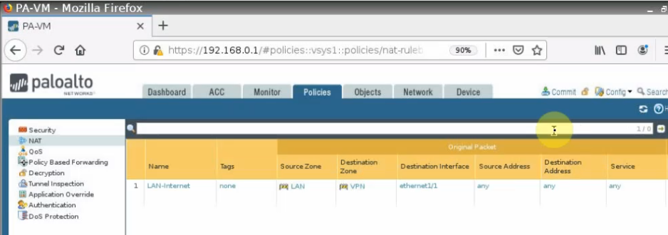
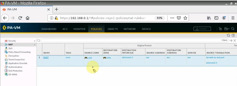
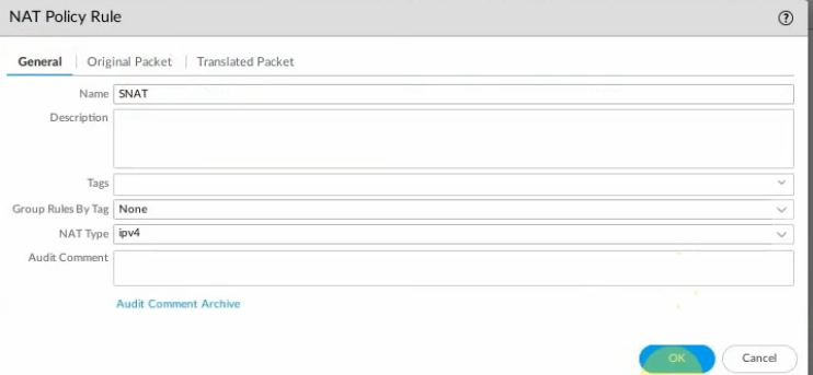
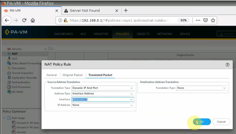
Create a SNAT policy to allow traffic from the PA LAN subnet to the Internet.
On the Destination interface, should choose e1/1. This is because VPN site-to-site traffic does not use NAT.
Ping 8.8.8.8 from PA LAN subnet.
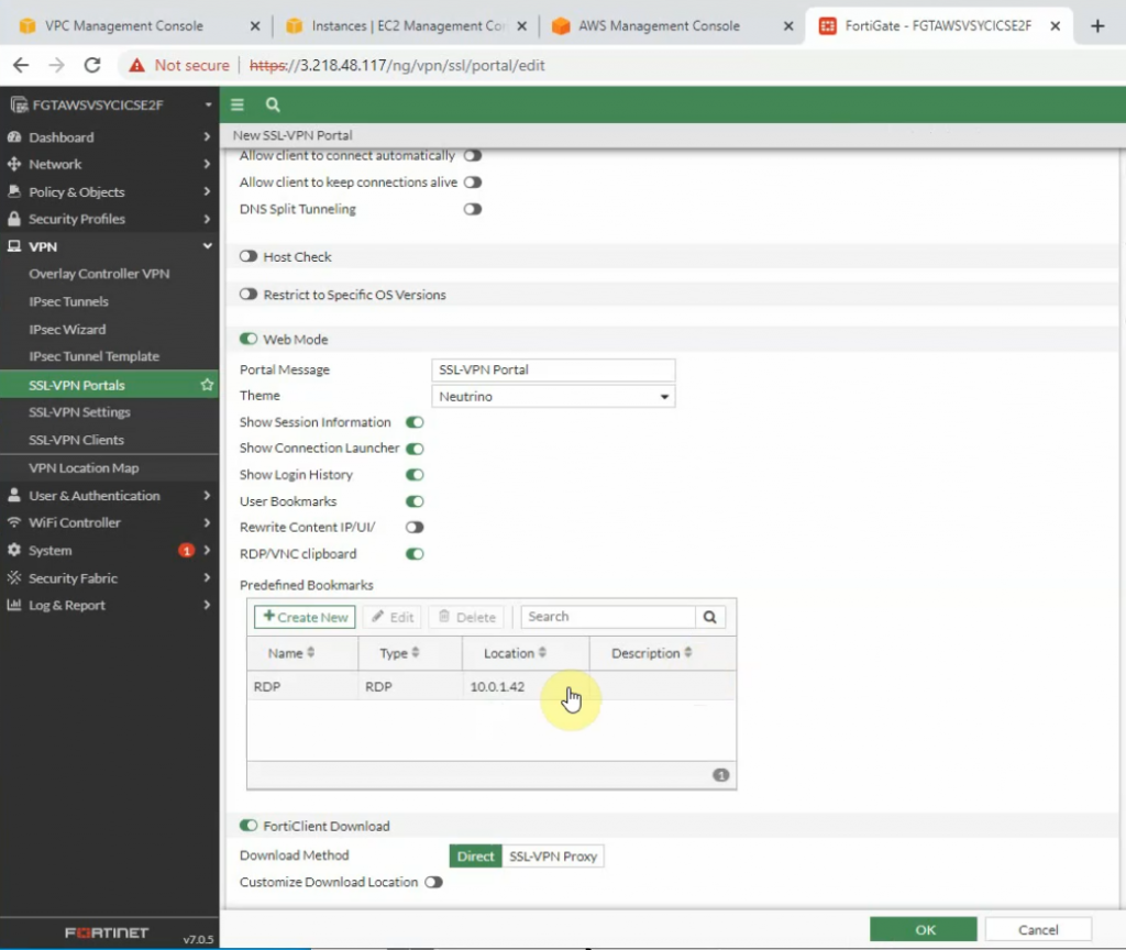
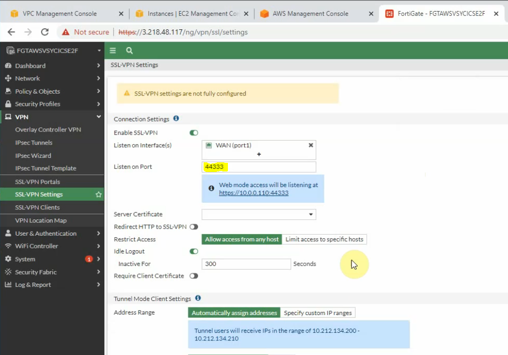
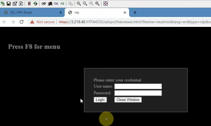
+ Create an SSLVPN portal on FortiGate to allow to access FG private subnet on the SSLVPN zone.
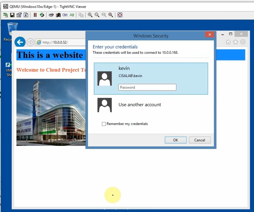
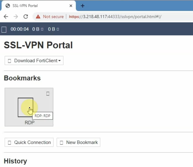
RDP to Windows 2016 instance private subnet on AWS is 10.0.1.42
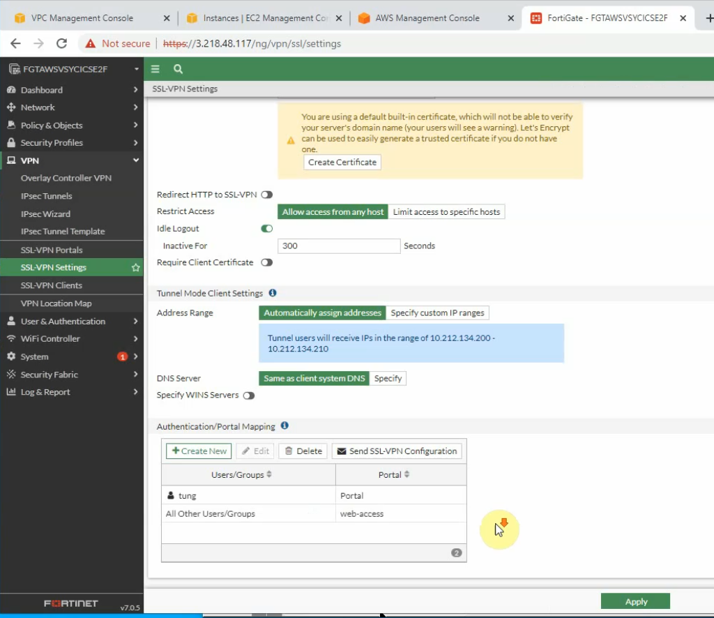
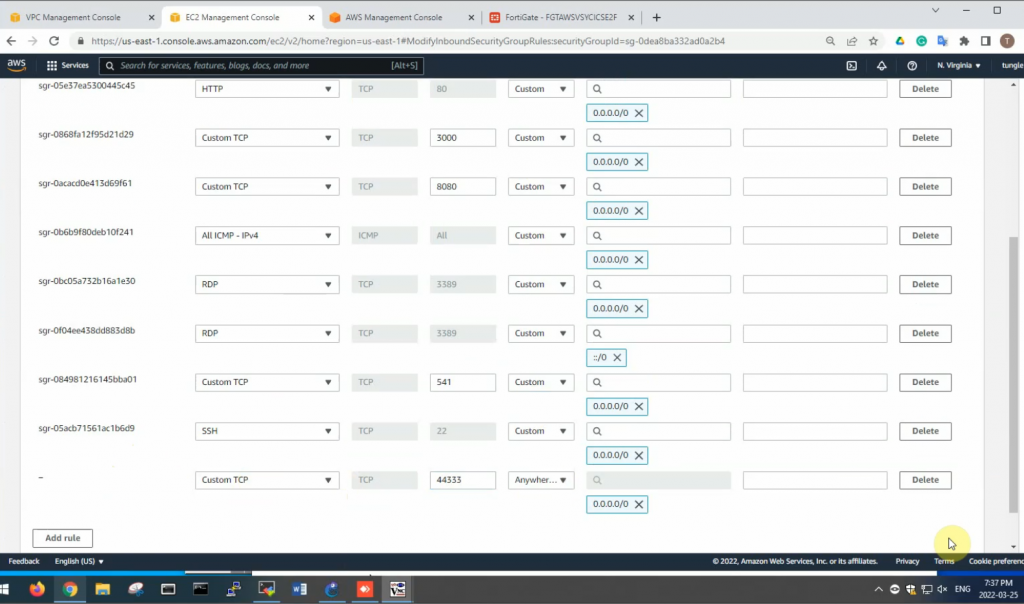
On SSLVPN setting, enable SSLVPN via 44333 port.
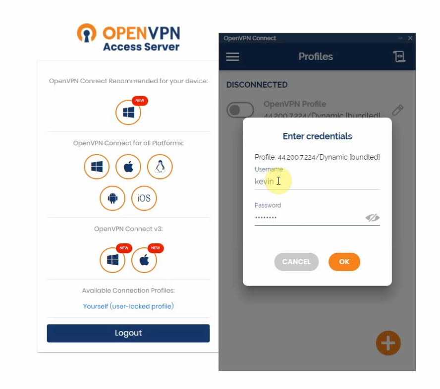
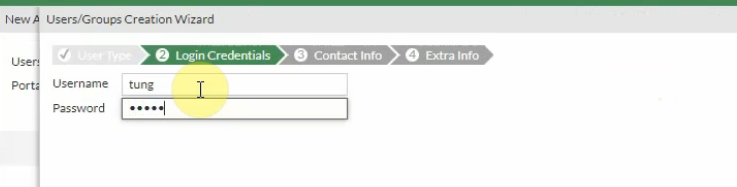
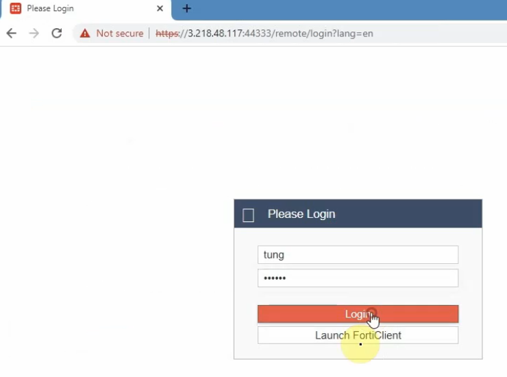
Create a new username and password to access SSLVPN.
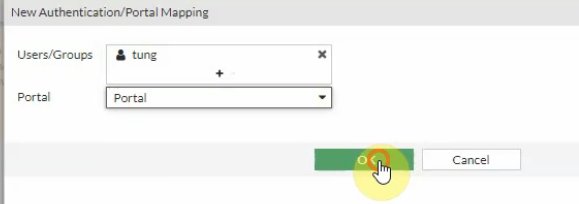
Then assign this user to the portal that we have created on previous step.
Edit the Security Group to allow Internet traffic to SSLVPN port is 44333.
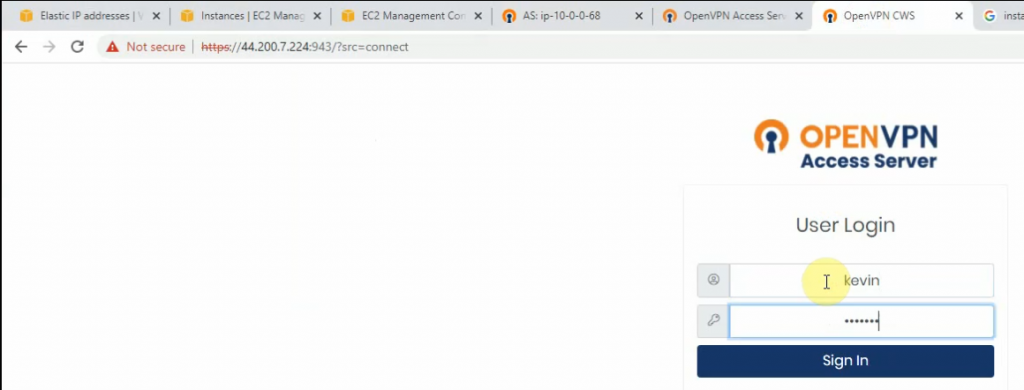
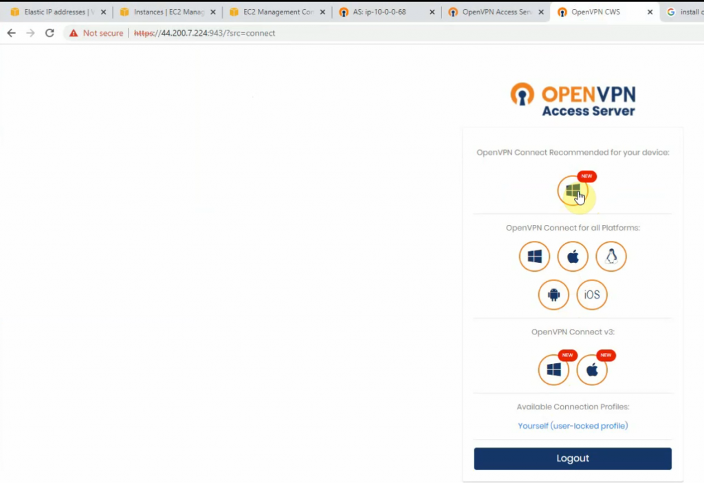
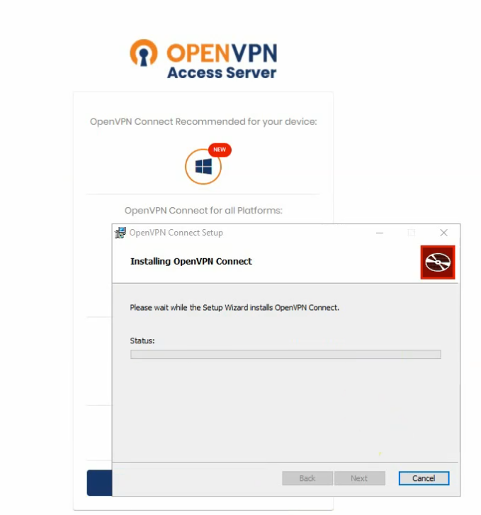
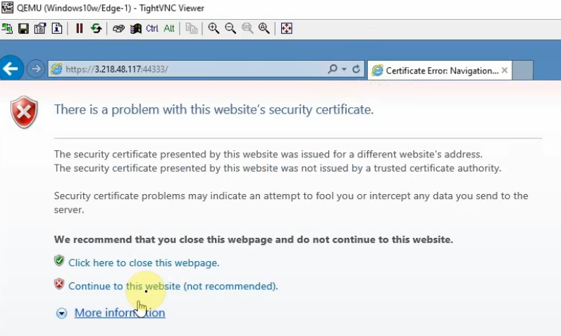
From a Windows machine, access SSLVPN portal on FG.
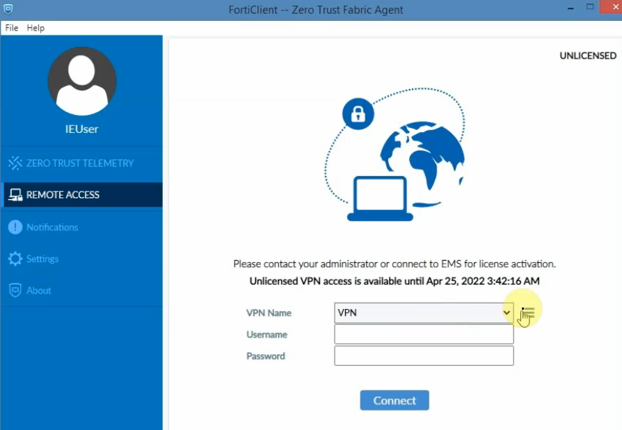
Also, we can use Forticlient to access if we have a license.