Tag Archives: Cloud

Count how many IP addresses in AWS US-East-1 region

In this article, I will demonstrate how to count how many IP addresses in US-East-1 region.

We can get a list of IP address from AWS.

https://ip-ranges.amazonaws.com/ip-ranges.json

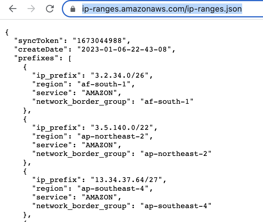
Download and save the JSON file to aws-ip-ranges.json in the present working directory.

Invoke-WebRequest -Uri https://ip-ranges.amazonaws.com/ip-ranges.json -OutFile aws-ip-ranges.json

Load the JSON file and convert JSON formatted file to custom PSObject of PowerShell.

$data = Get-Content -Path aws-ip-ranges.json -Raw | ConvertFrom-Json

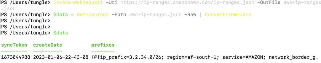
Extract the list of IP addresses for the US-East-1 region and AMAZON service.

$ip_addresses = $data.prefixes | Where-Object { $_.region -eq 'us-east-1' -and $_.service -eq 'AMAZON' } | Select-Object -ExpandProperty ip_prefix

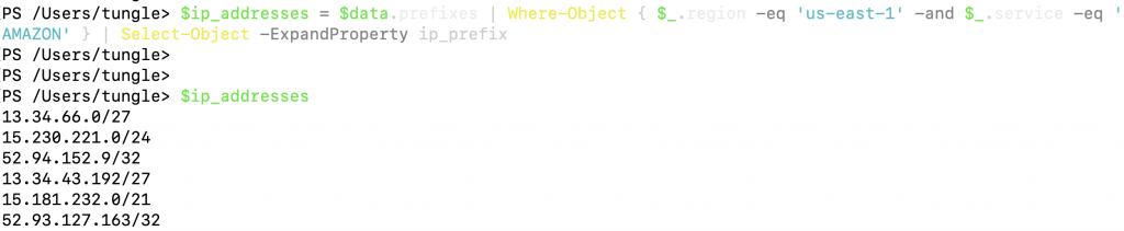
Below is a PS script.

# This script is using to extract IP address in US-East-1 region of AWS
# Download and save the JSON file to aws-ip-ranges.json in the present working directory
Invoke-WebRequest -Uri https://ip-ranges.amazonaws.com/ip-ranges.json -OutFile aws-ip-ranges.json

# Load the JSON file and convert JSON formatted file to custom PSObject or Hashtable object of PowerShell
$data = Get-Content -Path aws-ip-ranges.json -Raw | ConvertFrom-Json

# Extract the list of IP addresses for the US-East-1 region1 and service is AMAZON
$ip_addresses = $data.prefixes | Where-Object { $_.region -eq 'us-east-1' -and $_.service -eq 'AMAZON' } | Select-Object -ExpandProperty ip_prefix

# Print the list of IP addresses of AWS US-East-1 Region
$ip_addresses

Run the script.

./aws-ip.PS1

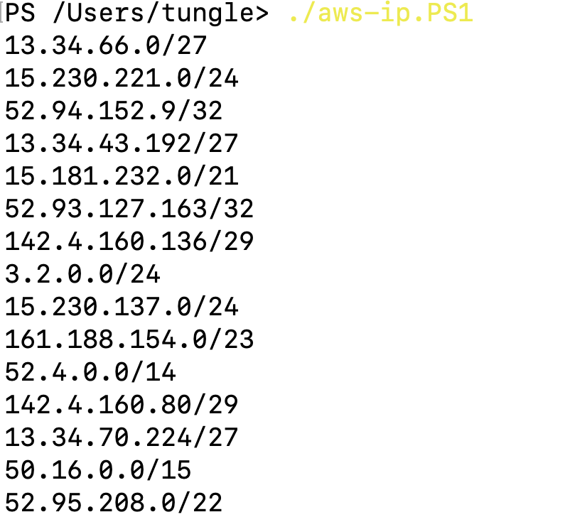
Save all range IP addresses when running the script aws-ip.PS1 to aws-ip.txt

./aws-ip.PS1 > aws-ip.txt

Using the following PowerShell script to extract how many IP addresses in the Amazon CIDR subnet such as 52.4.0.0/14.

param(
    [string]$filename
)

function Count-IPs([string]$netblock) {
    # Get CIDR value from the netblock
    $cidr = [int]$netblock.Split('/')[1]
    # Return the number of IP addresses in the netblock above
    return [math]::Pow(2, 32 - $cidr)
}

if (!$filename) {
    # Display the error message if the filename parameter is not provided
    Write-Output "Usage: $($MyInvocation.MyCommand) <filename with CIDR masks>"
}

$ipcount = 0
Get-Content $filename | ForEach-Object {
    $ipcount += Count-IPs $_
}
Write-Output $ipcount

Run the script.

./countips.PS1 aws-ip.txt

There are 17,728,227 IP addresses in AWS US-East-1 region.

Set up VPN IPSEC site-to-site between Palo Alto in AWS and FortiGate in premises

This is a diagram that I have used for this lab.

Understanding on deploying Palo Alto instance in AWS is necessary for this lab (https://tungle.ca/?p=3979).

On PA, Configure a tunnel.

Add a new static route into PA Virtual Route to allow traffic from the Private subnet to a LAN subnet in FortiGate.

Create IKE Crypto.
Create IPSEC Crypto.
Create an IKE Gateway.

Create an IPSEC tunnel.

Create PA-LAN and FG-LAN network.
Create both Security rules to allow traffic from PA-LAN to FG-LAN and vice versa.
Back to AWS – Route tables. Add a new static route on the Private Route.

Add 192.168.10.0/24 into the routes and select “Private Interface” on the target.

Move on to FortiGate.

Configure interfaces.

Configure default routes on FG.

Configure IPSEC VPN on FG.

Create a FG-LAN and PA-LAN address.
Set up a new static route to allow traffic from FG-LAN subnet in FG to PA-LAN subnet in AWS.
Create Security Polices to allow traffic from FG-LAN to PA-LAN and vice versa.
Setup IP address on Kali machine.

Ping from Kali machine to Windows instance (10.0.3.134).

Ping from Windows instance to Kali machine (192.168.10.2).

Check Security Policy status.
The FortiGate IPSEC tunnel is UP.

Back to Palo Alto in AWS. We can see the traffic from PA-LAN to FG-LAN and vice versa.

The Palo Alto IPSEC tunnel is UP.

Deploying Palo Alto Firewall in Amazon AWS

This is a diagram that is used to deploy this lab.

Below are a couple of steps to deploy Palo Alto on AWS

  • Create a key pair, VPC, subnets, Internet Gateway, Route tables
  • Create a Palo Alto instance on AWS
  • Create Elastic IP addresses for Management and Public interface
  • Create a Windows VM on private subnet
  • Modify Security Group to allow traffic from the Internet to PA and Windows VM
  • Configure a Security Policy, NAT to allow traffic from the Internet to the Windows VM via RDP

Create a key pair.

Create a VPC.
Create a management subnet.

Create a Public subnet on availability zone US-East-1a. I got an error that I cannot create a Palo Alto if my VPC is randomly used US-East-1e.

Create a Private subnet.

There are 3 subnets on AWS Subnet VPC.

Create a Internet Gateway and attach it into your VPC.
Rename Route table to Private Route

Create a Public Route table.

Associate Management and Public Subnet to Public Route table.

Launch a Palo Alto Firewall on AWS.

Select “Management Subnet” in the Subnet setting.

Leave “Add Storage” and Tags as default.

Use a Security Group that has been generated automatically when creating the PA VM.

Actions – Monitor – get instance screenshot.

Go to EC2 – Network interfaces. Rename a name of the “-” to “Management interface”.

Create a Public interface of PA and link it to the “Public Subnet”.

Rename a name of the “-” to “Public interface”.

Attach it into PA.

Create a Private interface of PA and link it to the “Private Subnet”.

Rename a name of the “-” to “Private interface”.

Attach the Private interface into PA.

Disable “Change source/dest. check” in all interfaces.

Assign two Elastic IP addresses for Public interface.
Associate EIP to Public interface.

Select “Public interface”

Rename “-” to Public EIP.

Back to Route table,

Create a default route via Internet Gateway.

Back to PA instance, rename it into PaloAltoVM.

Access SSH to Palo Alto instance.

Change password of user admin.

Log into PA via a web browser.

Back to EC2 – EIP. Assign a permanent Elastic IP address (IP address does not change when the instance is stopped) for Management interface to and rename “-” to Mgmt EIP.

Access the PA via Elastic IP address.

Configure the Public interface (e1/1) of PA.

Configure the Private interface (e1/2) of PA.

Commit the settings.

Create a default route via the Public interface.

Create a local route to allow traffic from the PVC network via the Private interface.

Back to VPC, edit routes in “Private route”.

Add a default route via “Private network”.

Back to EC2 – instances, create a new Windows VM in the Private network.

Select “Private Subnet” in Subnet setting and Disable in “Auto-assign Public IP”.

Add the ICMP line to allow ICMP traffic in this Security Group.

Move to PA, create 2 security polices to allow traffic from Private Zone to Public Zone and vice versa.

Create a SNAT and DNAT to allow traffic from Windows VM to the Internet and RDP traffic from Internet to Windows VM in Private subnet.

SNAT.

DNAT.

Back to AWS – EC2 – Security Group, add RDP and ICMP into the following Security Group.

Add RDP and ICMP into this Security Group.

Now access RDP to Windows VM via Public EIP.

Disable Windows Firewall.

Ping 8.8.8.8 from Windows instance.

Implementing VPN site-to-site between Palo Alto on-prem and Palo Alto on the Google Cloud Platform

This is a diagram that I have used for this lab.

I have set up the first part for Palo Alto on GCP (https://tungle.ca/?p=3760). Now, I go to set up the VPN site-to-site between Palo Alto on-prem and Palo Alto on GCP.

On Palo Alto on-prem.

Setup DHCP service on the e1/2 interface.

Set the default route on Palo Alto.

Create a tunnel 1 on Palo Alto.

Create an IKECrypto.

Create an IPSECCrypto.

Create an IKEGateway.

Create an IPSECTunnel.

Create network objects for LAN subnets of Palo Alto on-prem and on GCP.

Create both security policies to allow traffic from LAN subnets on Palo Alto – GCP to LAN subnets on Palo Alto on-prem and vice versa.

Create a static route to allow traffic from LAN subnets of Palo Alto on-prem to LAN subnets of Palo Alto on the cloud.

Create SNAT to allow the local network to access the Internet.

Create another access rule to allow traffic from the LAN network to access the Internet.

The Kali machine on the LAN network is able to access the Internet.

Back to Palo Alto on GCP.

Create a tunnel 1 on Palo Alto.

Create an IKECrypto.

Create an IPSECCrypto.

Create an IKEGateway.

Create an IPSEC tunnel.

Create network objects for LAN subnets for Palo Alto on-prem and on the cloud.

Create both security policies to allow traffic from LAN subnets on Palo Alto on GCP to LAN subnets on Palo Alto on-prem and vice versa.

Create a static route to allow traffic from LAN subnets of Palo Alto on the cloud to LAN subnets of Palo Alto on-prem.

Go to the vpc-inside network, and create “Add route” to add a new route to LAN subnets of Palo Alto on-prem.

Ping Kali’s machine from Windows 2016 VM on GCP.

Ping the Windows 2016 VM on Kali’s machine.

The IPSEC tunnel is up on Palo Alto on-prem.

The IPSEC tunnel is up in Palo Alto on GCP.

Deploying Palo Alto Firewall on Google Cloud Platform

This is a diagram that I have used in this lab.

Below are several main steps in this lab:

  • Create 3 vpc networks: vpc-mgmt (10.0.0.0/24), vpc-outside (10.0.1.0/24), and vpc-inside (10.0.2.0/24) on GCP.
  • Create ingress/egress Firewall rules on the vpc networks.
  • Launch Palo Alto instance on GCP.
  • Launch Windows 2016 instance on the inside network.
  • Create a default route, security rules, SNAT, and DNAT for RDP traffic from the Internet to Windows 2016 instance via Palo Alto.
  • Modify the default route for the inside network to use the Palo Alto instance.

VPC Network – Route tables.

Go to VPC network – Firewall – Create a firewall rule for ingress/egress traffic from and to the network 0.0.0.0/0.

The ingress-mgmt rule.

The egress-mgmt rule.

The ingress-outside rule.

The egress-outside rule.

The ingress-inside rule.

The egress-inside rule.

Go to Compute Engine – Create an instance – Marketplace – enter “Palo Alto” – select “VM-series Next-Generation Firewall (Bundle 1)” – click launch.

Click Enable on the Required APIs.

Back to create Palo Alto VM.

Using the puttygen to generate an SSH key pair. Click to save the public and private keys.

This is a public key that you need to submit when creating the Palo Alto VM on GCP.

Copy the key and pass it into the SSH key.

Select the interfaces like the following screenshot. Then, click “Deploy”.

Wait a couple of minutes to see the “Palo Alto has been deployed” notification.

Get the external IP address of mgmt and outside interfaces.

Compute Engine – VM instances – paloalto-vm1.

Click Edit.

Reserve the static IP address 10.0.0.2, 10.0.1.2 and 10.0.2.2 for mgmt, outside and inside network on Palo Alto.

Open Putty and load the private key that you have saved in the previous step.

Set password for the admin user and commit.
configure
set mgt-config users admin password
commit

Open your web browser and enter https://35.223.135.68.

Create a default route on Palo Alto.

Go to Compute Engine – Create a new Windows 2016 VM.

On External IP address, change from ephemeral to None. Then, click to create a VM.

Back to the VPC network – Routes to change the default route of the inside network to the Palo Alto instance. Delete the highlighted route as the screenshot below.

Create a new default route, and change the next hop instance from the internet gateway to use the Palo Alto instance.

Create a new Windows 2016 instance object on Palo Alto.

Create both access rules to allow traffic from the inside network to the outside, and from the Internet to the Windows 2016 VM.

The outside network to RDP service on the inside network.

Create SNAT to allow traffic from the inside network to the outside network via the Palo Alto.

Create a DNAT rule to allow RDP traffic from the Internet to Palo Alto and DNAT to Windows 2016 instance.

Click commit.

Open RDP on a Windows machine and enter the public IP address of the vpc-outside network on Palo Alto.

Enter your username and password.

We can see the RDP traffic in Palo Alto.

The Windows instance is able to access the Internet via Palo Alto.

AWS RDS MySQL on Multi-AZ Test Failover

This is a diagram that I have used to deploy this lab.

Create your VPC with two different subnets on different AZs.

Create a Linux instance.

Copy it into the User data setting.

#!/bin/bash
yum update -y
yum install httpd -y
wget https://wordpress.org/latest.tar.gz
tar -zxf latest.tar.gz
amazon-linux-extras install php7.4 -y

Create a WordPress-SG Security Group.

SSH to the Linux instance, and check httpd, php is installed on the machine.

rpm -qa | grep httpd
rpm -qa | grep php
sudo yum install php -y
sudo systemctl start httpd
sudo systemctl enable httpd
netstat -antp

Copy all files on WordPress directory to /var/www/html.

cd wordpress
sudo cp -r * /var/www/html
cd /var/www/html

Check HTTP service is running on the Linux instance.

Next, create a database subnet on your Amazon RDS by using both AZs.

Create a new DS database.

Enable “Multi-AZ DB instance”.

Create a wordpress database, username, and passowrd.

Open http://44.205.13.154 on your web browser to set up WordPress.

Create a new wp-config.php under /var/www/html directory, and paste the information on the screen to this file. Click “Run the installation”

The master RDS MySQL instance is on the IP address 10.0.1.187 on Availability zone 2.

Run the command below to verify RDS MYSQL failover.

while true; do host wordpress.c60vdekov0up.us-east-1.rds.amazonaws.com ; sleep 1; done

Then select Actions-Reboot to reboot the RDS instance. Enable the “Reboot with Failover” option.

Wait for around 1 to 2 minutes and refresh the WP web link. The WordPress site will be offline for around 1 minute when doing RDS failover. It can be seen that the RDS MySQL Endpoint has changed from 10.0.2.187 to 10.0.0.254.

RDS Endpoint has updated with the new address is 10.0.0.254 on us-east-1a.

The master RDS MySQL instance is on the IP address 10.0.0.254 on Availability zone 1.

Checking the WordPress site.

Implement WordPress HTTPS load balancing with Multi-AZs deployment for AWS RDS

This is a diagram that I have used for this lab.

There are several main steps that I have used in the lab.

  • Create four private subnets on four AZs.
  • Create a WordPress instance on the first AZ.
  • Create a new MySQL instance on Multi-AZs deployment.
  • Create an AMI image for the WordPress instance.
  • Create a Launch configuration.
  • Set up an Auto Scaling Group with your launch configuration.
  • Request ALB certificate via AWS Certificate Manager.
  • Configure HTTPS listener on ALB.
  • Configure the HTTP listener and redirect the HTTP traffic to HTTPS.
  • Create a CNAME record on your DNS zone for the Amazon domain name.
  • Test an Application Load Balancer for WordPress on multiple AZs with MySQL instance on Multi-AZ deployments.
  • Configure Amazon CloudFront.
  • Test an Application Load Balancer for WordPress on your cloudfront.net domain.

Create a new VPC.

Create 4 private subnets on 4 Availability zones.

Create and attach a new Internet Gateway to your VPC.

Create a static route 0.0.0.0/0 on your VPC.

Create a Linux instance.

Copy it into the User data setting.

#!/bin/bash
yum update -y
# Install Apache web service
yum install httpd -y
# Download WordPress 
wget https://wordpress.org/latest.tar.gz
tar -zxf latest.tar.gz
# Install php7.4
amazon-linux-extras install php7.4 -y

Create a WordPress-SG.

Create a new Security Group is WordPress-ALB-AutoScaling for ALB AutoScaling.

SSH to the Linux instance, and check httpd, php is installed on the machine.

rpm -qa | grep httpd
rpm -qa | grep php
sudo yum install php -y
sudo systemctl start httpd
sudo systemctl enable httpd
netstat -antp

Copy all files on WordPress directory to /var/www/html.

cd wordpress
sudo cp -r * /var/www/html
cd /var/www/html

Create an ip.php file on /var/www/html directory.

#sudo nano ip.php
<?php
echo "Local IP address: "; echo $_SERVER['SERVER_ADDR'];
echo "<br>";
echo "Public IP address: "; echo $_SERVER['SERVER_NAME']
?>

Install mod_ssl on the Linux instance.

sudo yum install mod_ssl

Create a TLS certificate for the Linux instance.

sudo openssl req -x509 -nodes -days 365 -newkey rsa:2048 -keyout /etc/pki/tls/private/localhost.key -out /etc/pki/tls/certs/localhost.crt

Restart apache web service.

sudo systemctl stop httpd
sudo systemctl start httpd

Check https is running on the Linux instance.

Go to RDS, and create a new database subnet.

Create a new database instance on AWS.

Create a database.

Open https://18.209.221.54 on your web browser to set up WordPress.

Create a new wp-config.php under /var/www/html directory, and paste the information on the screen to this file. Click “Run the installation”

Check the connection from WP to RDS instance via the port 3306.

Create an image for the WP instance.

Go to launch configuration and create a launch configuration.

On Advanced configuration – advanced details – Select “Assign a pubic IP address to any instances”

Select an existing security group. Click create a launch configuration.

Go to Auto Scaling Group and create a new one.

Enable “Internet-facing” on load balancing scheme.

On “Configure group size and scaling policies”.

Both WP instances have been automatically created via the AutoScaling group.

Go to the load balancer.

Click edit to create a new listener for port 443.

Create a new target group for HTTPS.

Click Next.

Select both instances, and select “include as pending below”. Then, click “create target group”.

Go back and change the listener.

Select “Request new ACM certificate” for ALB instance.

Click “Request a certificate”.

Enter your domain: alb.tungle.ca.

Go to your hosting DNS domain name.

Create a CNAME record is alb with Amazon ALB domain name as a screenshot below.

Copy and paste information on the Amazon certificate into your CNAME record.

Checking domain via nslookup command.

Back to configure listener setting, and choose the certificate that has been issued from AWS.

Delete the unnecessary HTTP listener.

Add the new listener on ALB to redirect port 80 to port 443.

Check target groups and verify both instances have healthy status on registered targets.

Access the ALB web link on your web browser.

Check load balancing on both WPs.

Refresh the web link.

Both WPS have accessed the same RDS instance (the master) on the IP address 10.0.2.224.

Go to Amazon CloudFront to create CloudFront distribution.

Enter your domain on the origin domain.

Select your certificate on “the custom SSL certificate”.

Leave the other settings default, then click Create distribution.

Image

Access your CloudFront domain.

Image
Image

Deploy an IPSEC VPN site-to-site between Palo Alto on-prem and Virtual Private Gateway on GCP

This is a diagram that I have used for the lab.

Create a new VPC network on GCP.

Search VPN keyword on the search function.

Click “Create VPN connection”.

Select Classic VPN.

Select tung-vpc on the network setting.

Create a new static IP address for your VPC.

Delete tunnel 2 because I have only used tunnel 1 in this lab. Then click Create.

Click gpc-pa-tunnel-1.

Edit the Routes to allow traffic from my tung-vpc network to the Internet via the Default Internet gateway.

We can see the static route from privatesubnet on GCP to the LAN subnets on Palo Alto has been created on the Routes section.

Check the Firewall and allow SSH from the Internet to Linux instance on the “privatesubnet”.

I have used “Allow all” to allow SSH from the Internet to Linux instance, We are able to change to only allow SSH protocol or port 22. Click Create.

Search “compute engine”, and click create an instance.

On network interfaces.

Click create.

Open SSH in browser windows on the Linux instance.

Go to FortiGate.

Create IP tunnel.

Phase 1.

Phase 2.

Create a static route to allow traffic from FortiGate LAN subnet to GCP privatesubnet.

Create both FG-LAN and GCP-LAN subnet.

Create both access rules to allow traffic from the FortiGate LAN subnet to the GCP private subnet and vice versa.

Ping from Kali machine to the Linux instance on GCP.

The tunnel is up on FortiGate.

Ping from Linux instance on GCP to Kali machine on FortiGate LAN subnet.

The tunnel is up on GCP as well.

Deploy an IPSEC VPN site-to-site between Palo Alto on-prem and Virtual Private Gateway on GCP

This is a diagram that I have used for the lab.

Create a new VPC network on GCP.

Search VPN keyword on the search function.

Click “Create VPN connection”.

Select Classic VPN.

Select tung-vpc on the network setting.

Create a new static IP address for your VPC.

Delete tunnel 2 because I have only used tunnel 1 in this lab. Then click Create.

Click gpc-pa-tunnel-1.

Edit the Routes to allow traffic from my tung-vpc network to the Internet via the Default Internet gateway.

We can see the static route from privatesubnet on GCP to the LAN subnets on Palo Alto has been created on the Routes section.

Check the Firewall and allow SSH from the Internet to Linux instance on the “privatesubnet”.

I have used “Allow all” to allow SSH from the Internet to Linux instance, We are able to change to only allow SSH protocol or port 22. Click Create.

Search “compute engine”, and click create an instance.

On network interfaces.

Click create.

Open SSH in browser windows on the Linux instance.

Back to Palo Alto.

IKECrypto.

IPSECCrypto.

IPSECTunnel.

Create both network objects for the Palo Alto-LAN subnet and GCP-LAN subnet

Create both access rules to allow traffic from Palo Alto LAN subnets to GCP privatesubnet.

This is the network interface on PA.

Create a new static route to allow traffic from PA LAN subnets to GCP privatesubnet.

Then, click commit.

Back to GCP.

Ping Kali machine on PA LAN subnet from the Linux instance on GCP.

On Kali machine, ping Linux instance on GCP.

The Palo Alto VPN site-to-site tunnel with GCP is up.

The IPSEC VPN site-to-site tunnel is up on GCP as well.

Set up an IPSEC VPN site-to-site between FortiGate on-prem and Microsoft Azure

This is a diagram that I have used for the lab. I have used the same topology to deploy VPN site to site between Azure and Palo Alto firewall on-prem (https://tungle.ca/?p=3338). Basically I removed the Palo Alto firewall and put FortiGate in the diagram.

Create a new virtual network is Azure-PA.

Change default network to PrivateSubnet is 10.0.1.0.

A subnet address range is 10.0.1.0/24

Click Create.

Create a new subnet.

A subnetwork address range is 10.0.0.0/24

Go to “Virtual network gateway” to create a new virtual network gateway.

Virtual network: Azure-PA.

Subnet: Gatewaysubnet 10.0.0.0/24

Public IP address name: VPNIP

Click Create.

Wait around from 20 to 30 minutes to see if the Deployment will be done.

Go to “Local network gateway” and create a new local network gateway.

An IP address is a public IP address of the Palo Alto firewall.

Address space is Palo Alto’s LAN subnets.

Clock create.

Go to “Virtual network gateways”, and select the virtual network gateways that we have created in the previous step.

Go to “Connections” – Add.

Enter a shared key (PSK) for VPN site-to-site.

Take note of the IP address of Azure VPN.

On FortiGate on-prem.

Create a static default route.

Configure an IPSEC Tunnel.

Phase 1.

Phase 2.

Create a new network object for FortiGate.

FG-LAN: 172.16.0.0/16

Azure-LAN: 10.0.0.0/16.

Create both access rules to allow traffic from FortiGate LAN subnets to your Azure VPN private subnets. Remember “Disable NAT” on these rules.

Create a static route to allow traffic from FortiGate LAN subnets to your Azure private subnets via the IPSEC VPN site-to-site IKEv2 tunnel.

Ping from Kali machine to Windows 2016 on Azure.

The tunnel is up on FortiGate.

Ping a Kali machine on FortiGate LAN subnet from Azure.

Back to VPN2S, we can see the VPN status connection is “Connected”.