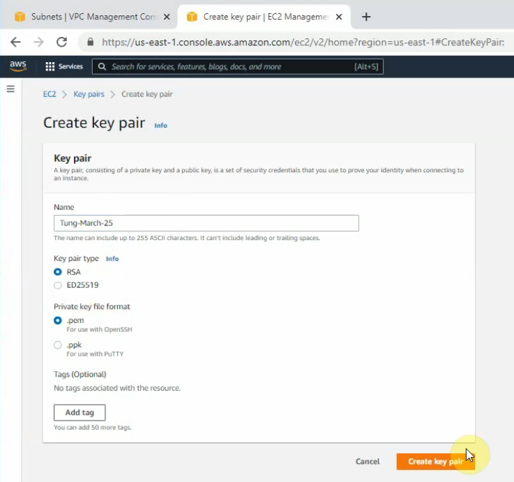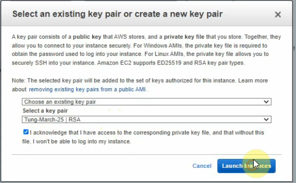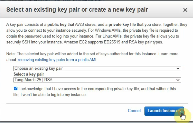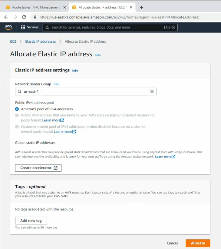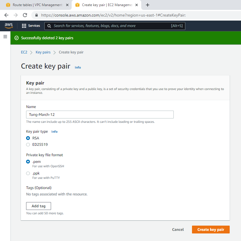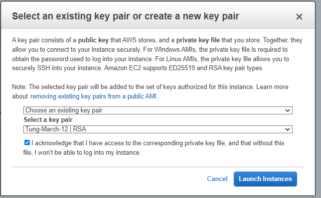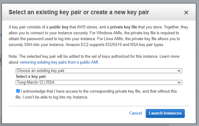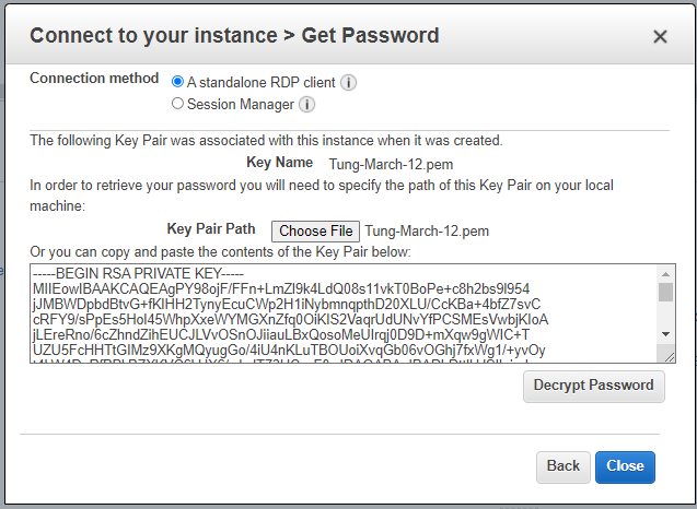
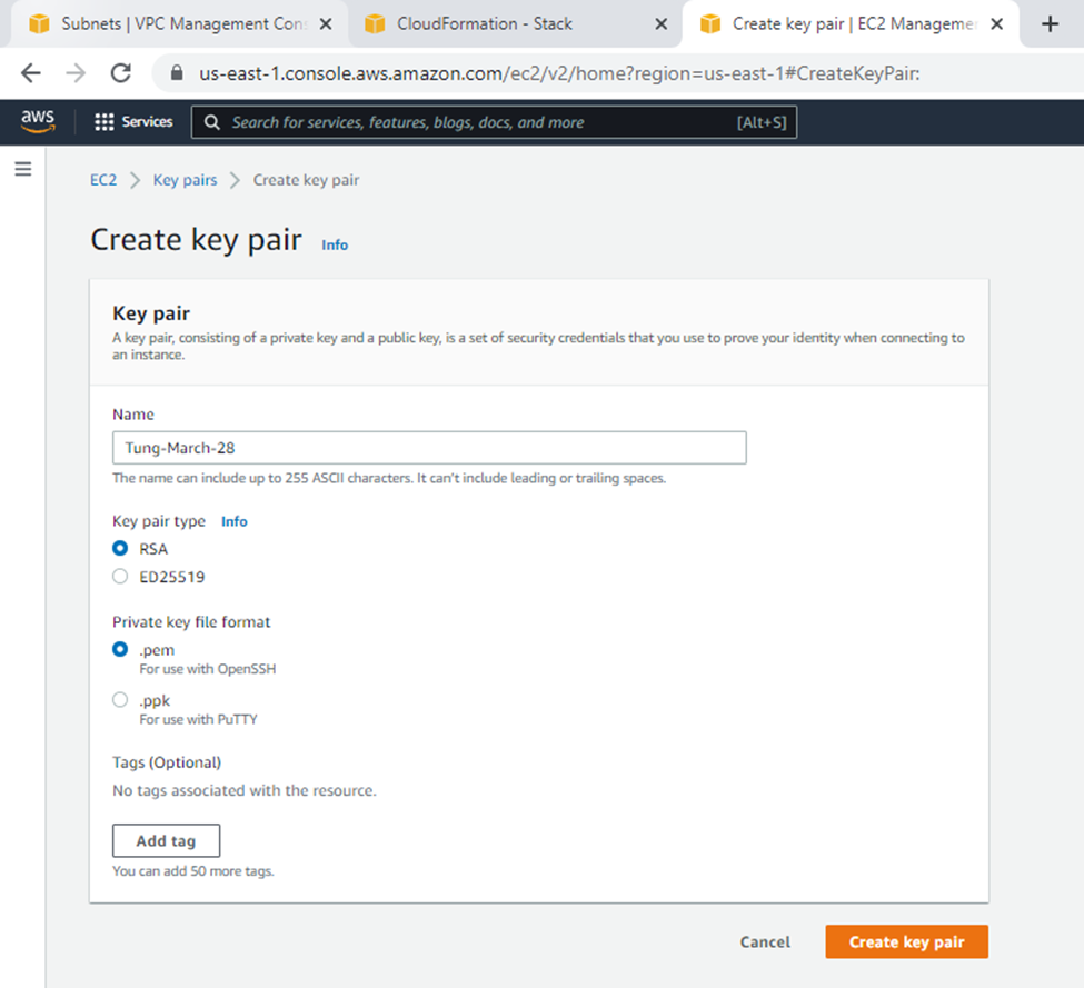
Create a new key pair.
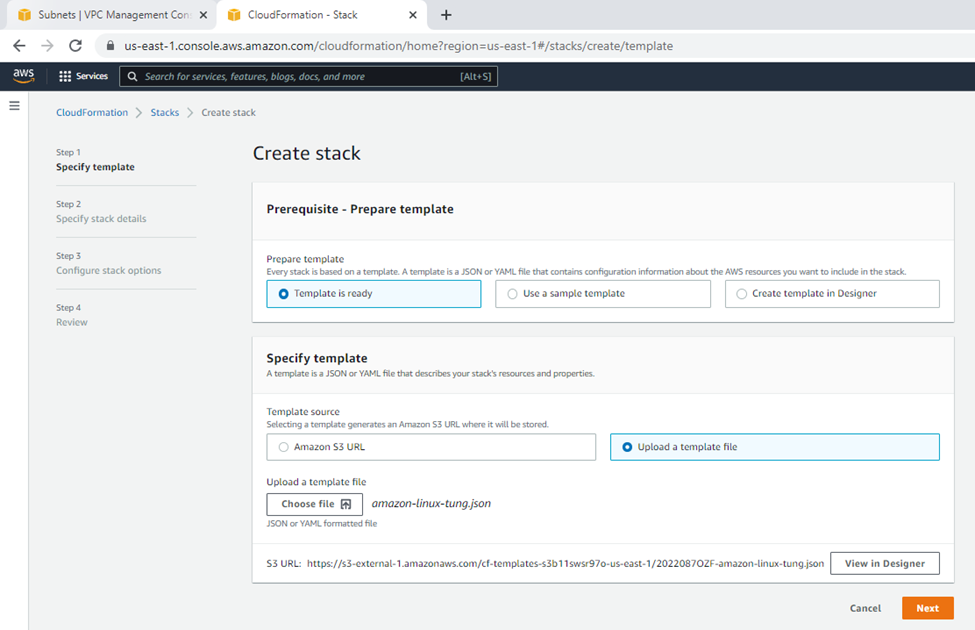
Upload the template to stack on AWS Cloudformation.
Upload a template to stack.
{
"AWSTemplateFormatVersion" : "2010-09-09",
"Description" : "AWS CloudFormation Sample Template VPC_with_PublicIPs_And_DNS: Sample template that creates a VPC with DNS and public IPs enabled. Note that you are billed for the AWS resources that you use when you create a stack from this template.",
"Parameters": {
"KeyPair": {
"Description": "Name of the keypair to use for SSH access",
"Type": "String"
}
},
"Resources" : {
"VPC" : {
"Type" : "AWS::EC2::VPC",
"Properties" : {
"EnableDnsSupport" : "true",
"EnableDnsHostnames" : "true",
"CidrBlock" : "10.0.0.0/16"
}
},
"PublicSubnet" : {
"Type" : "AWS::EC2::Subnet",
"Properties" : {
"VpcId" : { "Ref" : "VPC" },
"CidrBlock" : "10.0.0.0/24"
}
},
"InternetGateway" : {
"Type" : "AWS::EC2::InternetGateway"
},
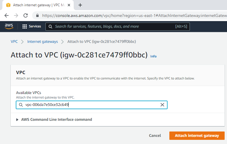
"VPCGatewayAttachment" : {
"Type" : "AWS::EC2::VPCGatewayAttachment",
"Properties" : {
"VpcId" : { "Ref" : "VPC" },
"InternetGatewayId" : { "Ref" : "InternetGateway" }
}
},
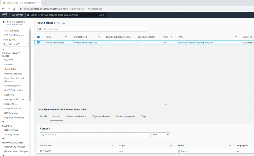
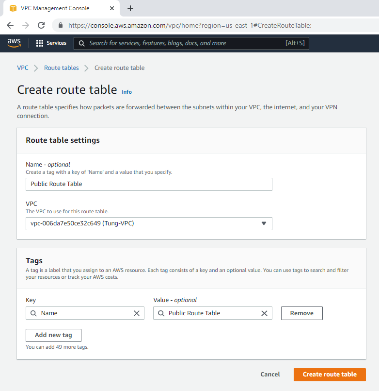
"PublicRouteTable" : {
"Type" : "AWS::EC2::RouteTable",
"Properties" : {
"VpcId" : { "Ref" : "VPC" }
}
},
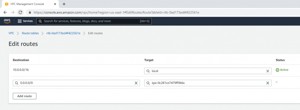
"PublicRoute" : {
"Type" : "AWS::EC2::Route",
"DependsOn" : "VPCGatewayAttachment",
"Properties" : {
"RouteTableId" : { "Ref" : "PublicRouteTable" },
"DestinationCidrBlock" : "0.0.0.0/0",
"GatewayId" : { "Ref" : "InternetGateway" }
}
},
"PublicSubnetRouteTableAssociation" : {
"Type" : "AWS::EC2::SubnetRouteTableAssociation",
"Properties" : {
"SubnetId" : { "Ref" : "PublicSubnet" },
"RouteTableId" : { "Ref" : "PublicRouteTable" }
}
},
"PublicSubnetNetworkAclAssociation" : {
"Type" : "AWS::EC2::SubnetNetworkAclAssociation",
"Properties" : {
"SubnetId" : { "Ref" : "PublicSubnet" },
"NetworkAclId" : { "Fn::GetAtt" : ["VPC", "DefaultNetworkAcl"] }
}
},
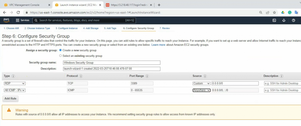
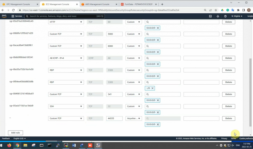
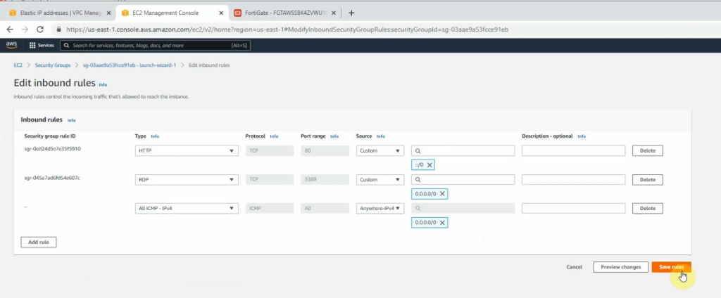
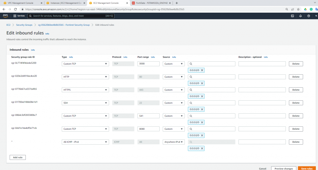
"WebServerSecurityGroup" : {
"Type" : "AWS::EC2::SecurityGroup",
"Properties" : {
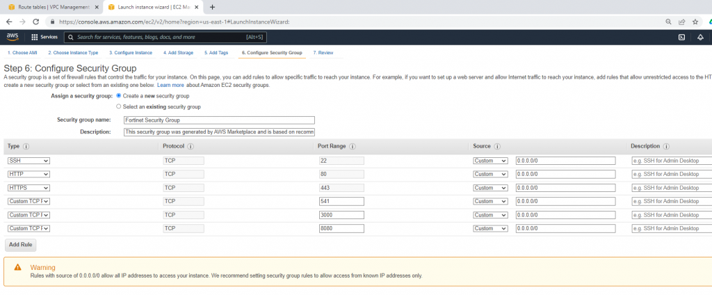
"GroupDescription" : "Enable HTTP ingress",
"VpcId" : { "Ref" : "VPC" },
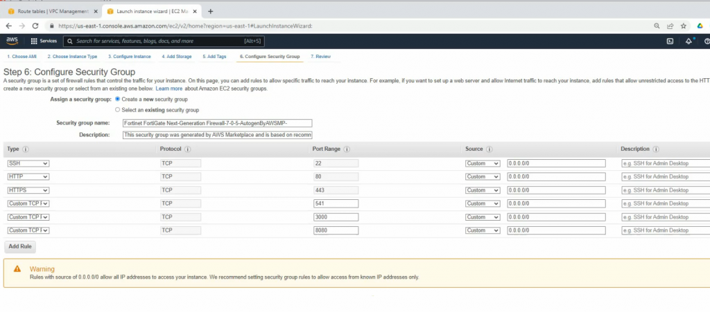
"SecurityGroupIngress" : [
{"IpProtocol" : "tcp","FromPort" : "80","ToPort" : "80","CidrIp" : "0.0.0.0/0"},
{"IpProtocol" : "tcp", "FromPort" : "22", "ToPort" : "22", "CidrIp" : "0.0.0.0/0"}]
}
},
"WebServerInstance": {
"Type": "AWS::EC2::Instance",
"Properties": {
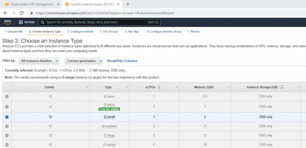
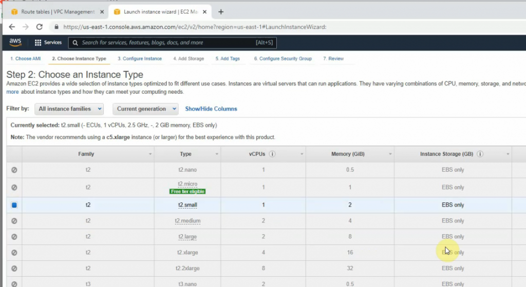
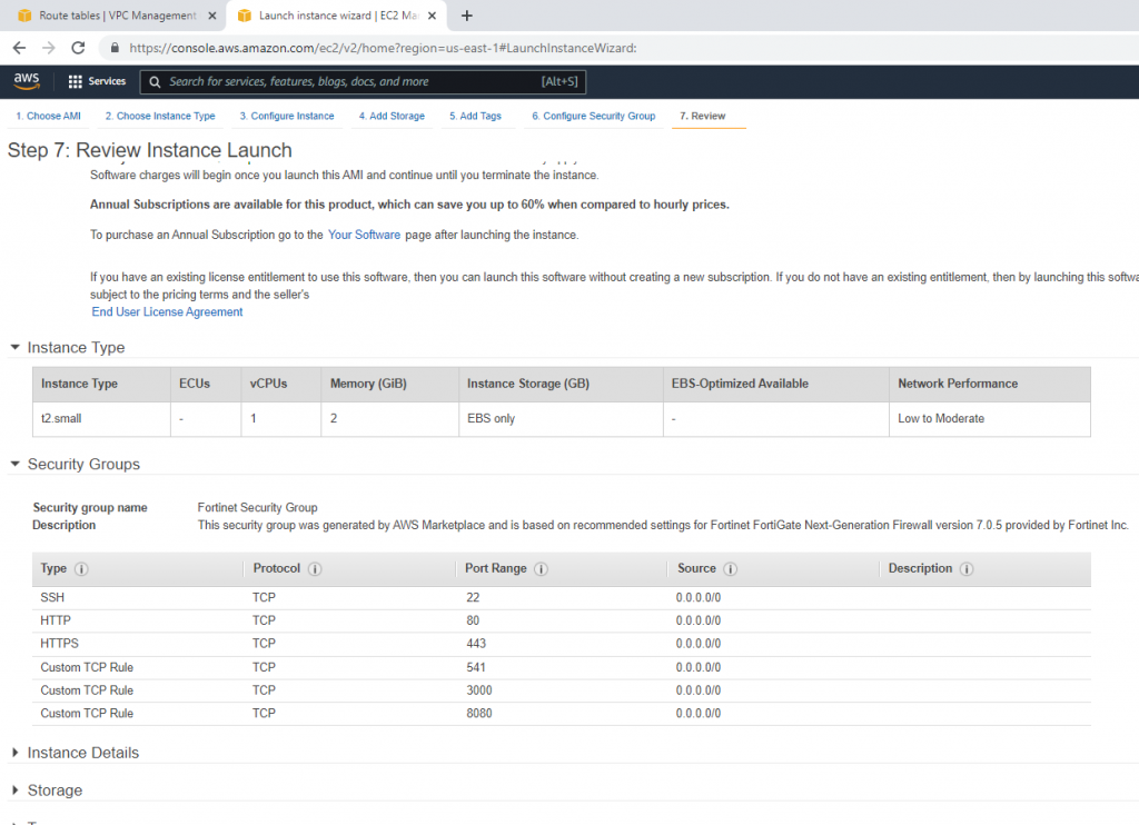
"InstanceType": "t2.micro",
"ImageId": "ami-8c1be5f6",
"NetworkInterfaces" : [{
"GroupSet" : [{"Ref": "WebServerSecurityGroup"}],
"AssociatePublicIpAddress" : "true",
"DeviceIndex" : "0",
"DeleteOnTermination" : "true",
"SubnetId" : {"Ref": "PublicSubnet"}
}],
"KeyName": {
"Ref": "KeyPair"
},
"UserData": {
"Fn::Base64": {
"Fn::Join": [
"\n",
[
"#!/bin/bash -xe",
"sudo yum update -y",
"sudo yum install httpd -y",
"sudo /etc/init.d/httpd start",
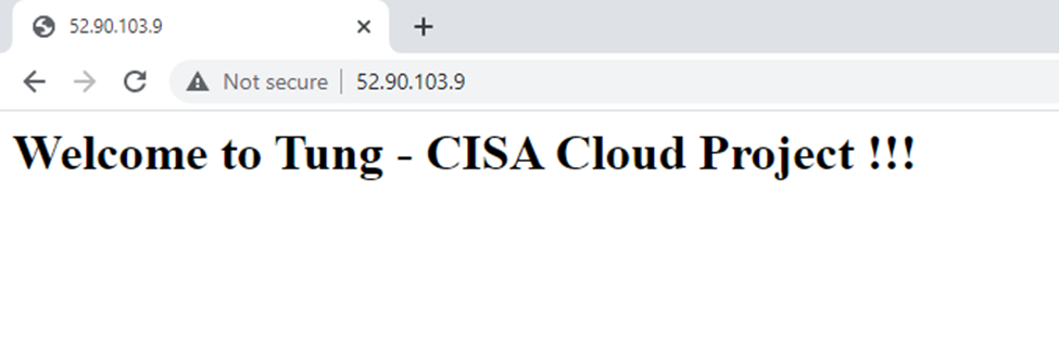
"echo \"<html><body><h1>Welcome to Tung - CISA Cloud Project !!!</h1>\" > /var/www/html/index.html",
"echo \"</body></html>\" >> /var/www/html/index.html"
]
]
}
}
}
}
},
"Outputs" : {
"URL" : {
"Description" : "URL of the sample website",
"Value" : { "Fn::Join" : [ "", [ "http://", { "Fn::GetAtt" : [ "WebServerInstance", "PublicDnsName" ]}]]}
}
}
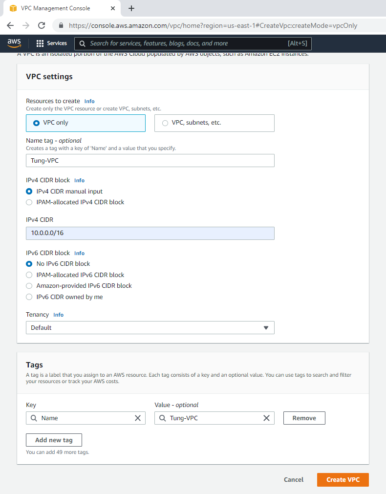
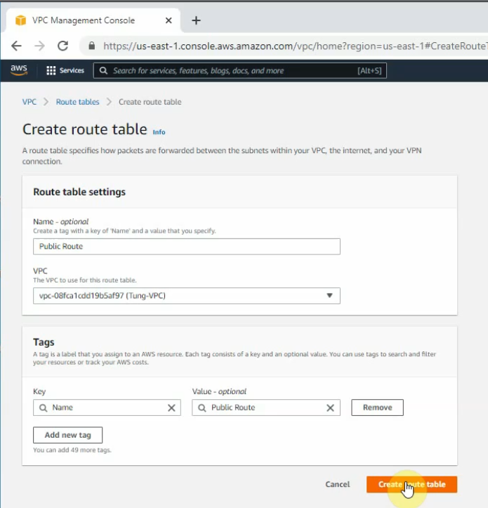
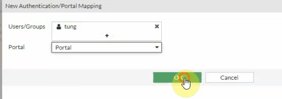
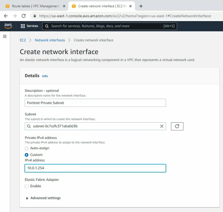
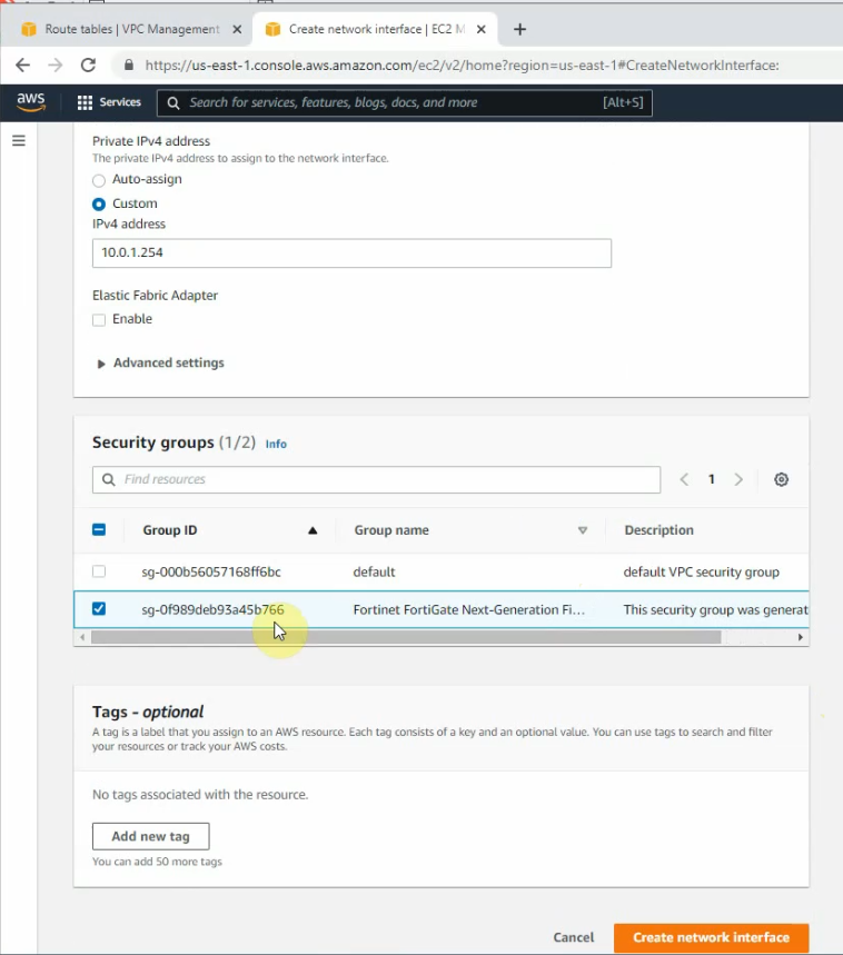
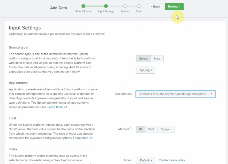
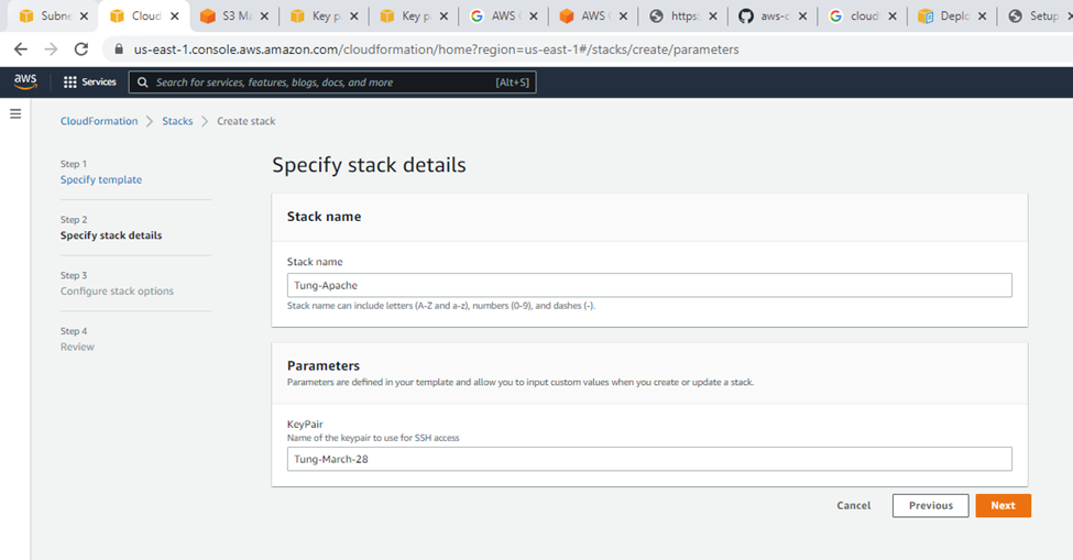
}Specify stack details.
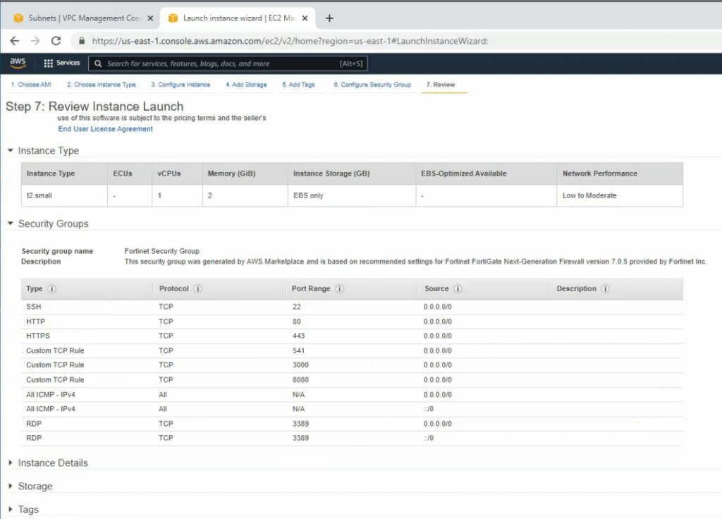
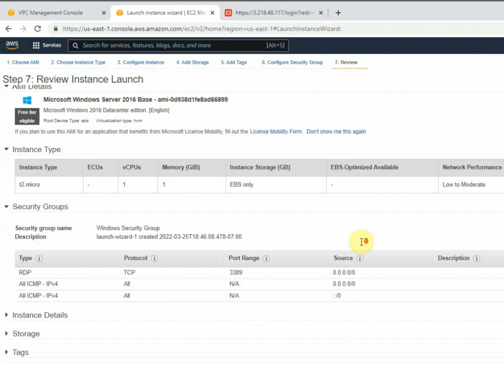
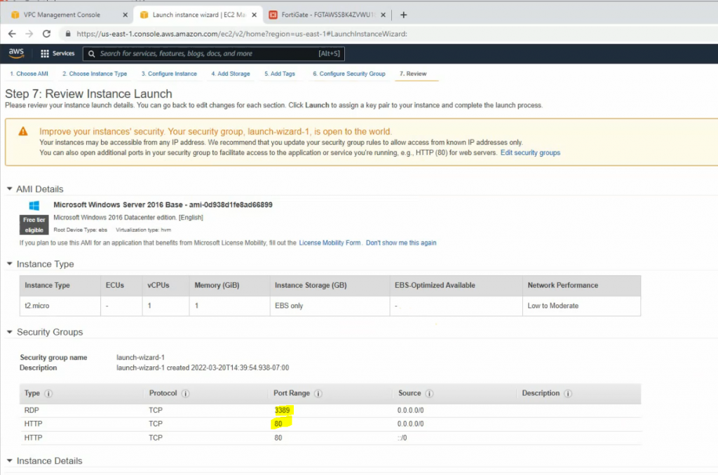
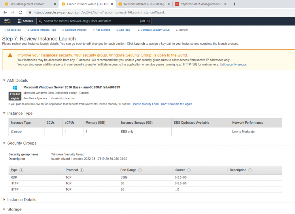
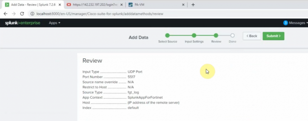
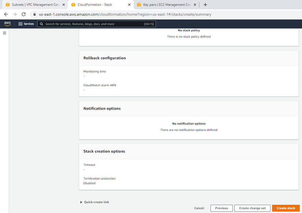
Review.
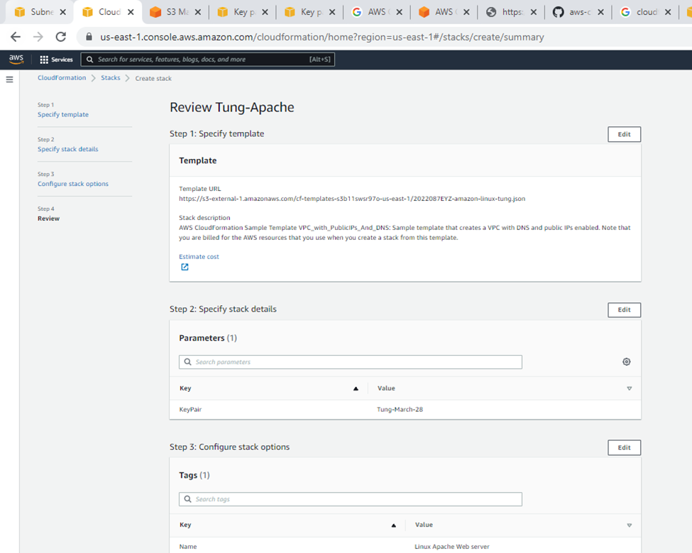
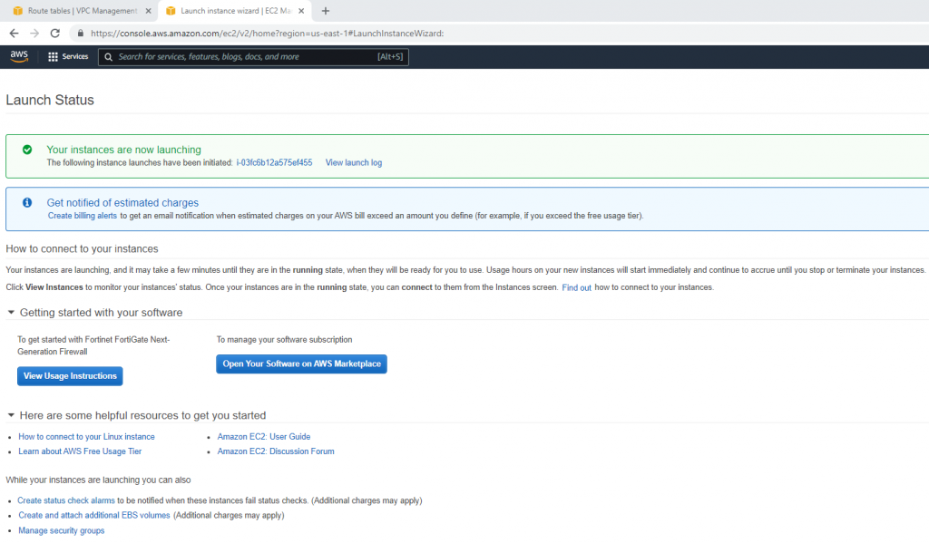
Click create a stack.
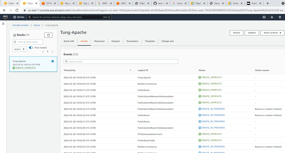
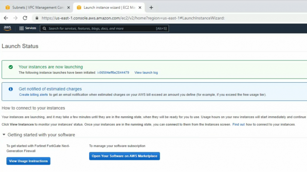
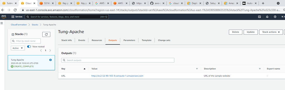
Output.
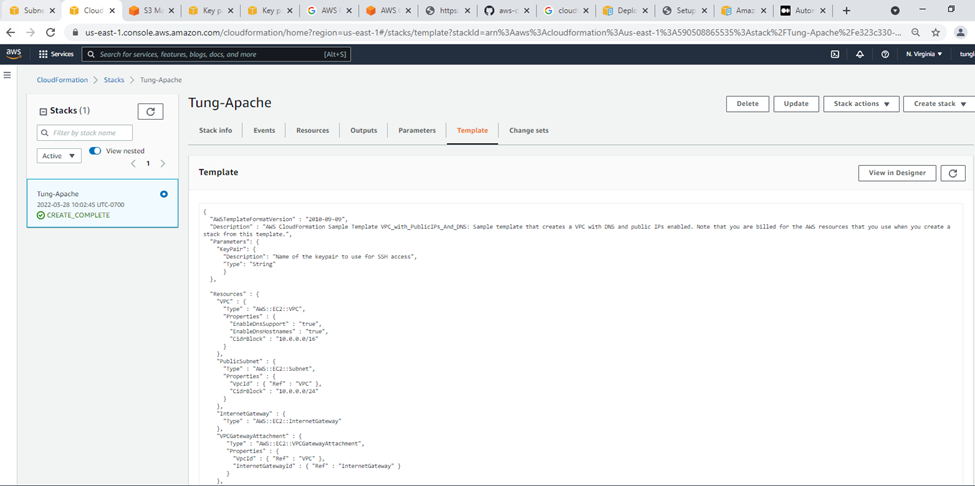
Templates.
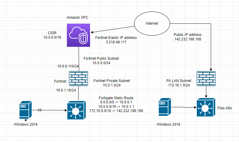
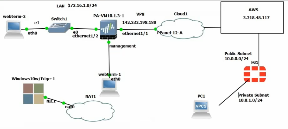
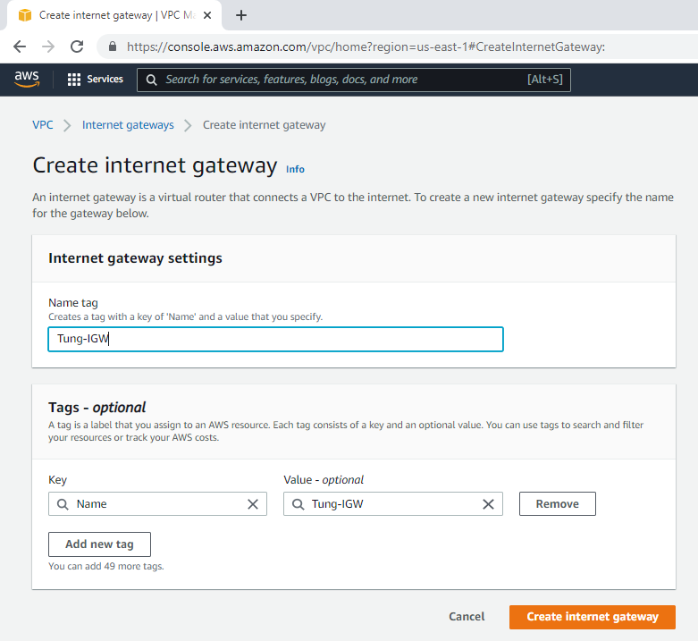
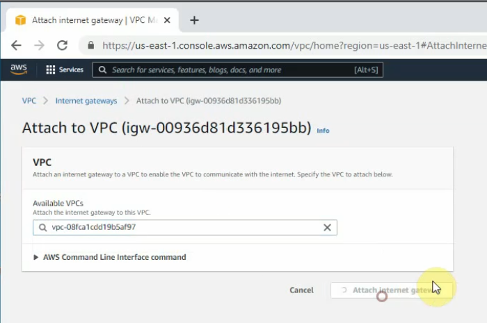
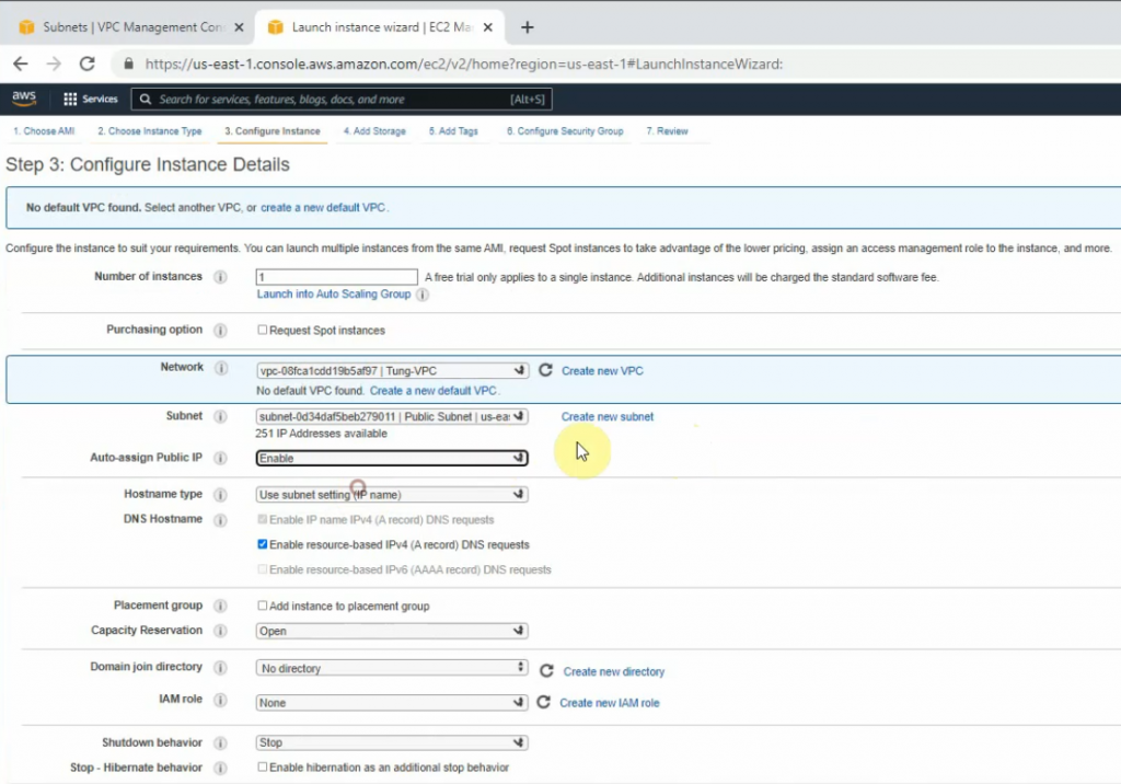
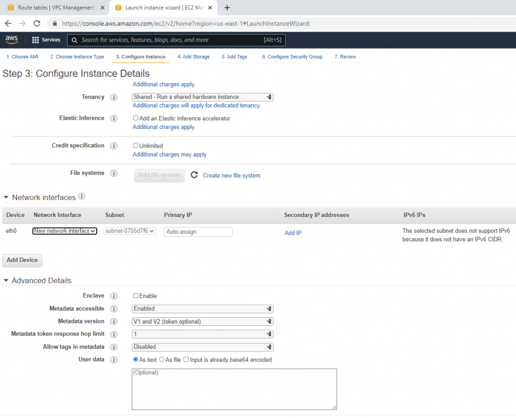
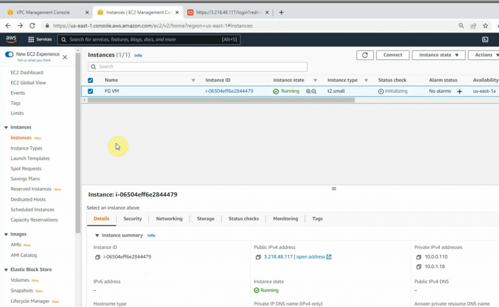
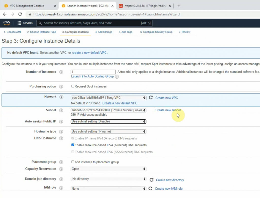
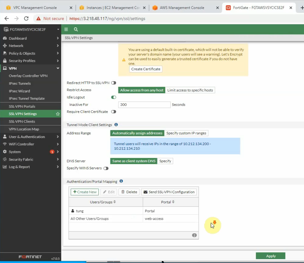
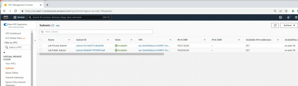
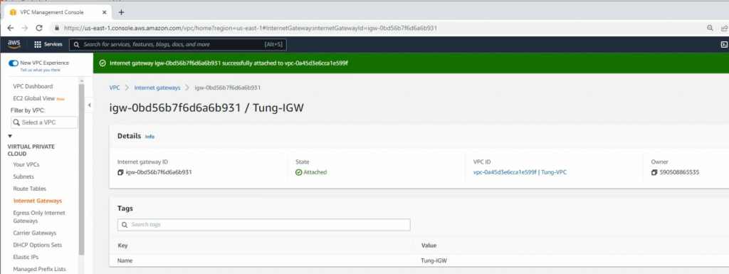
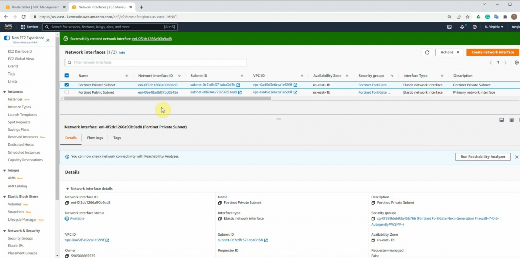
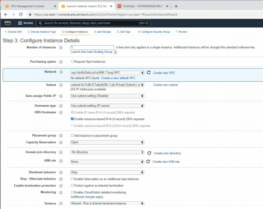
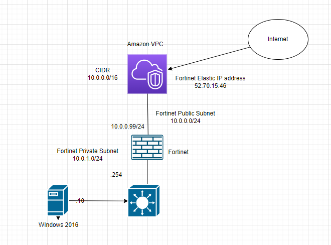
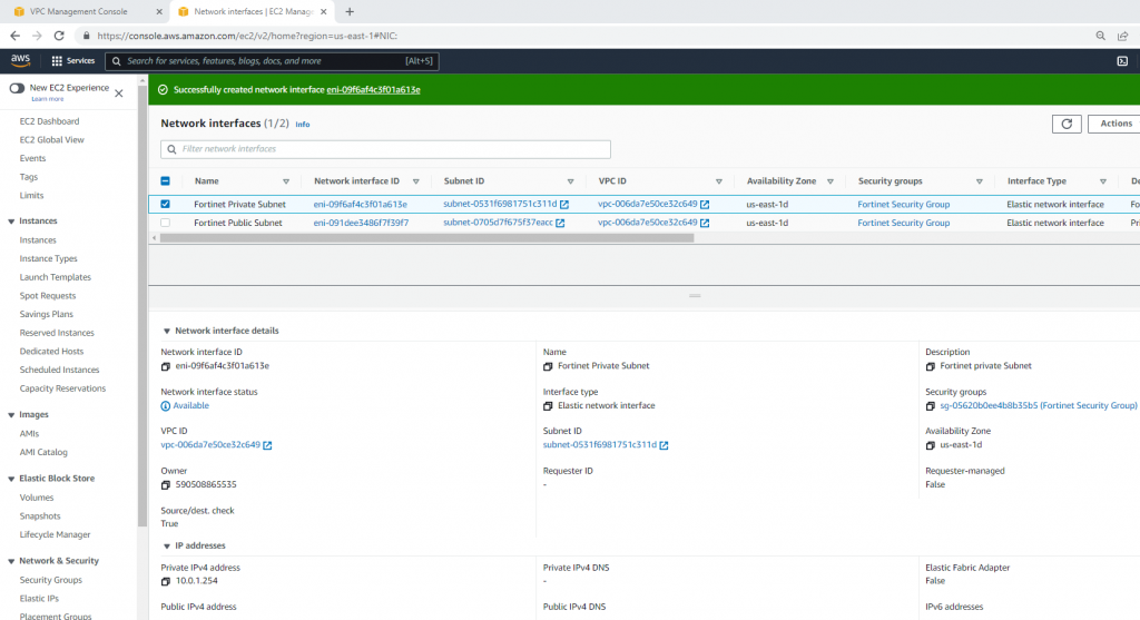
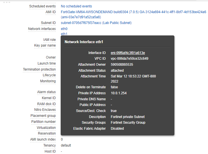
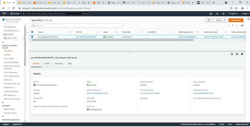
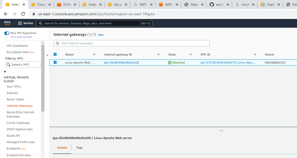
Check your VPC.
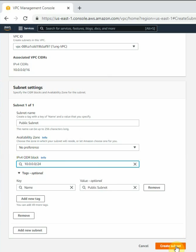
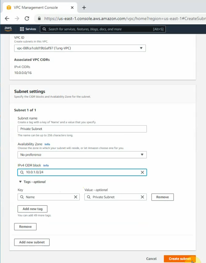
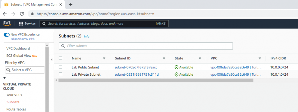
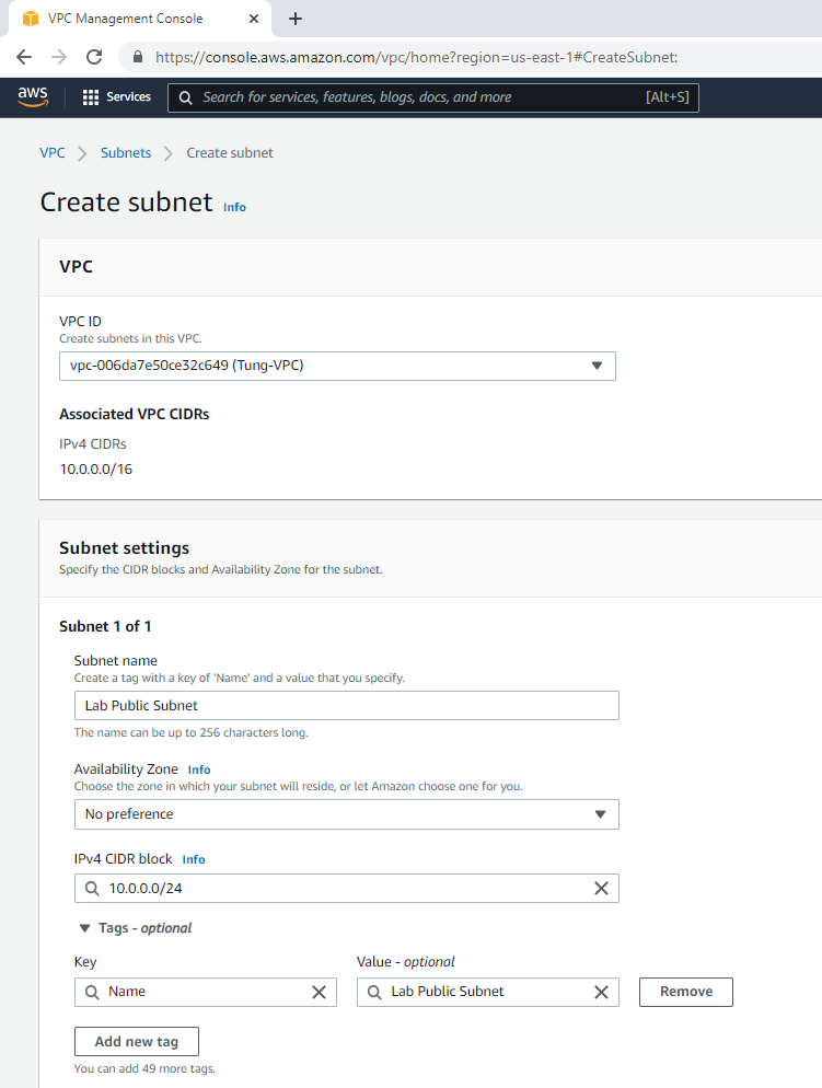
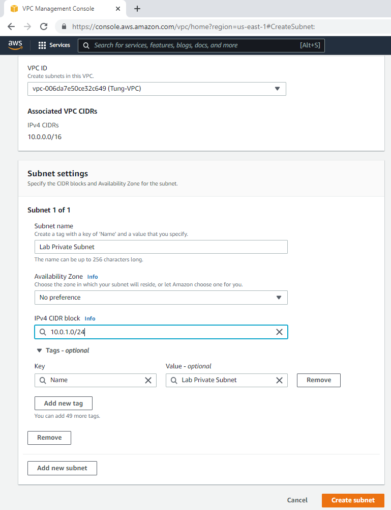
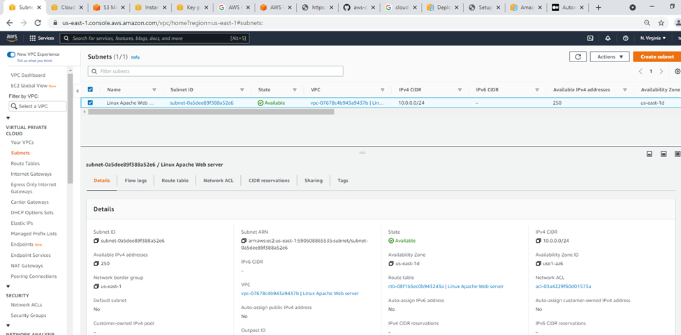
Subnets.
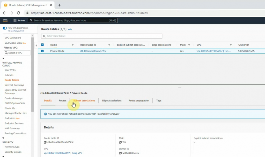
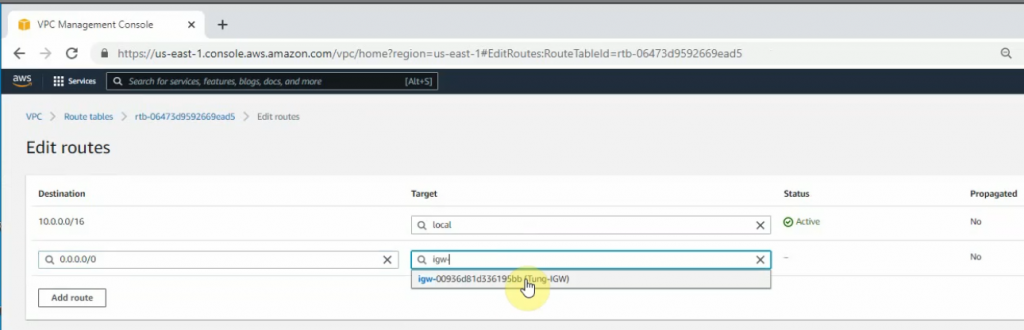
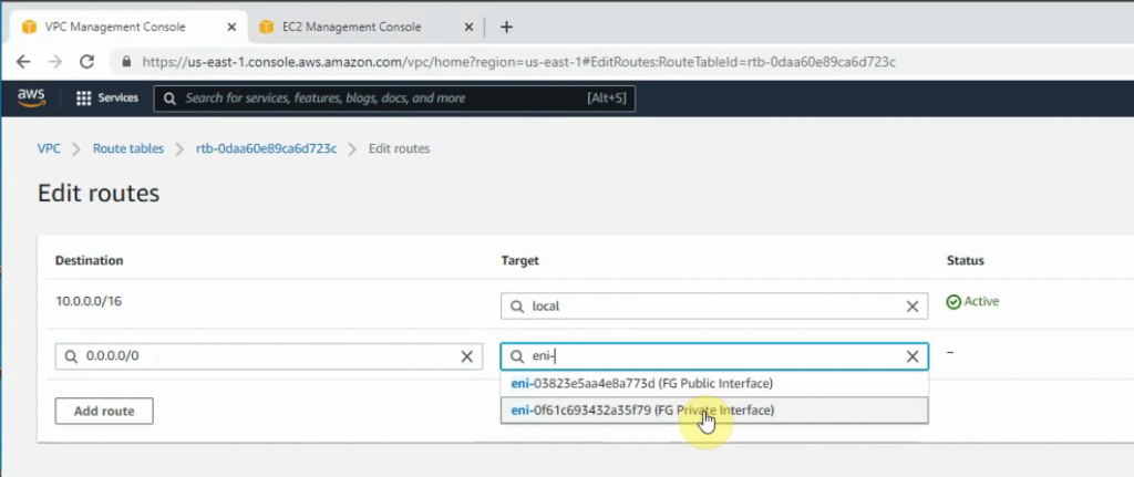
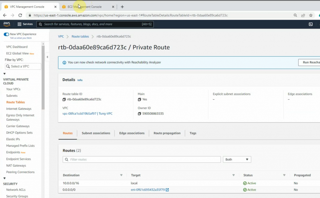
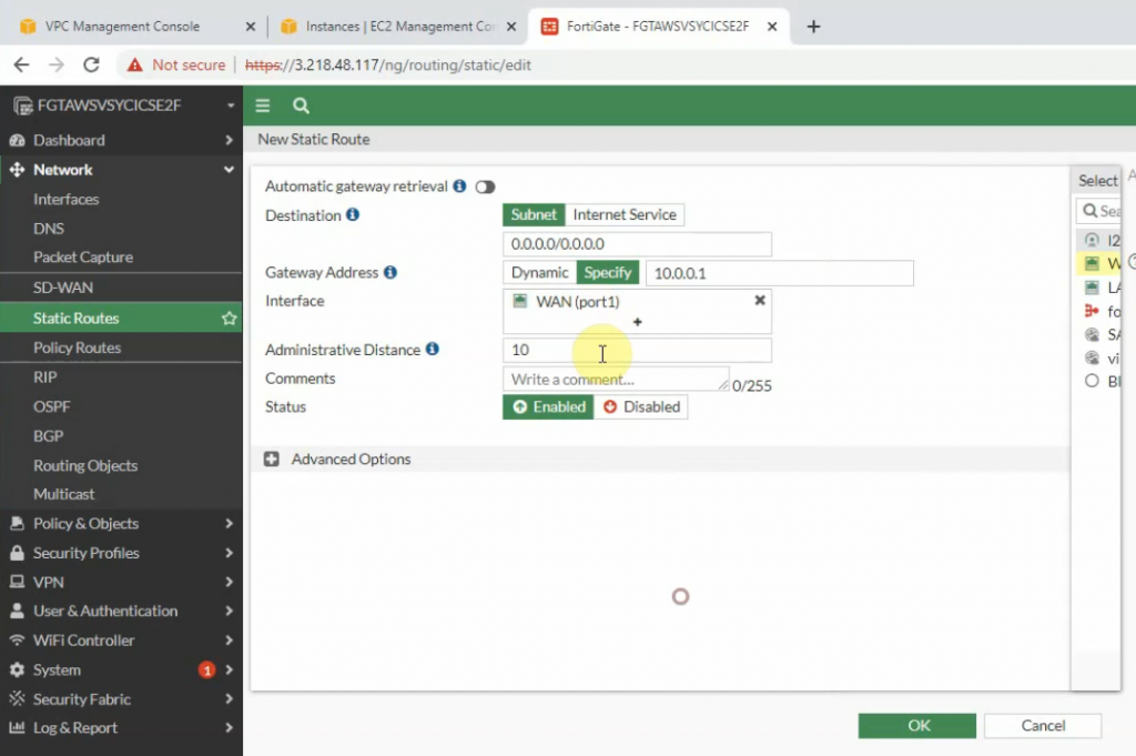
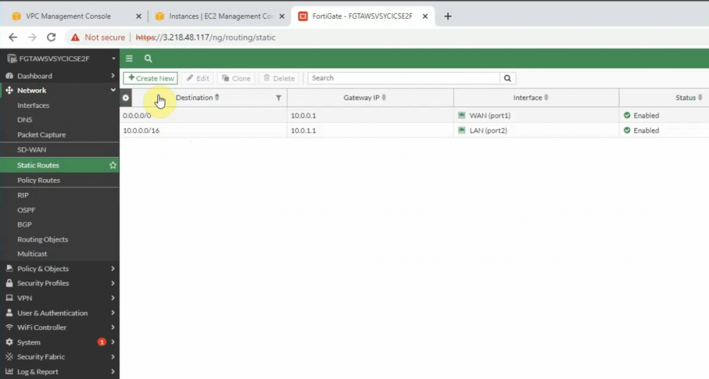
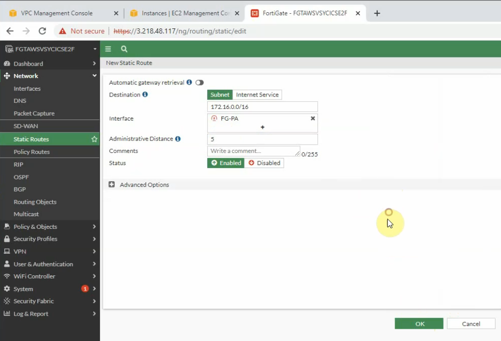
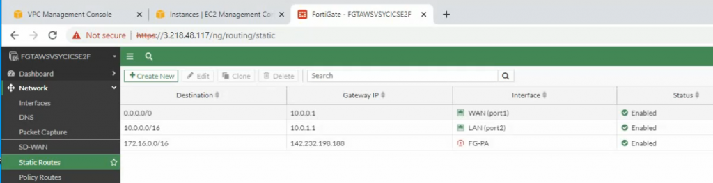
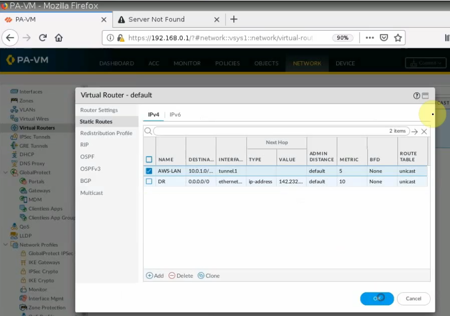
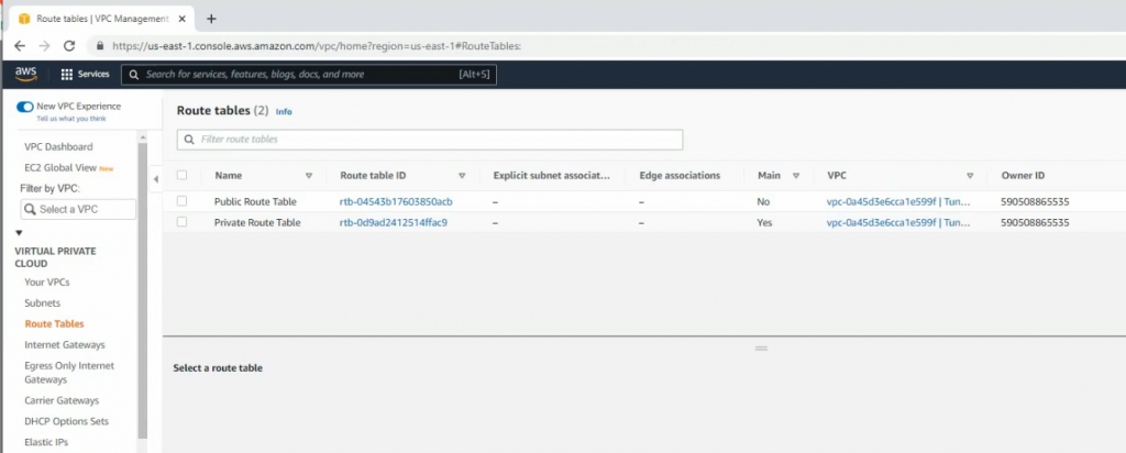
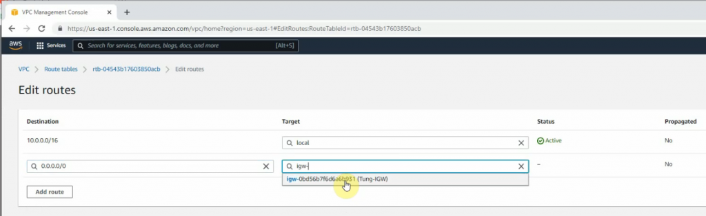
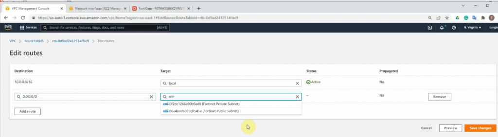
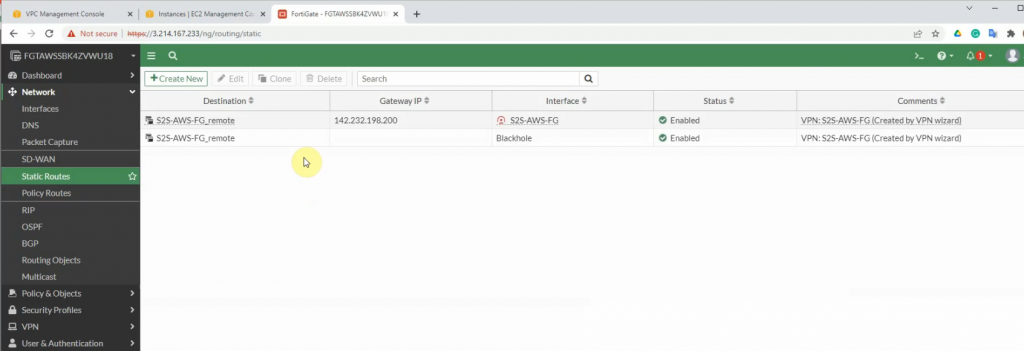
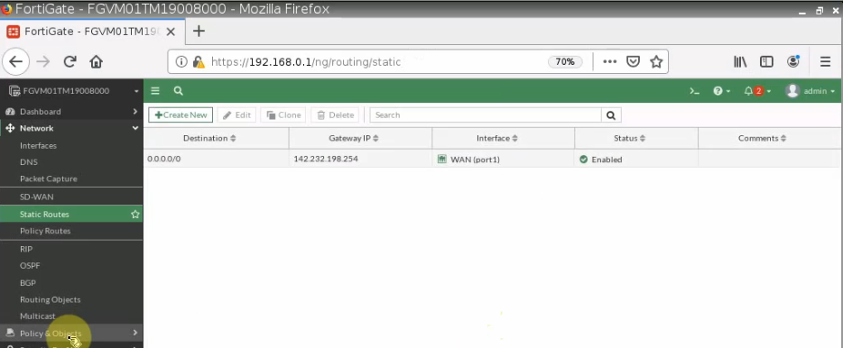
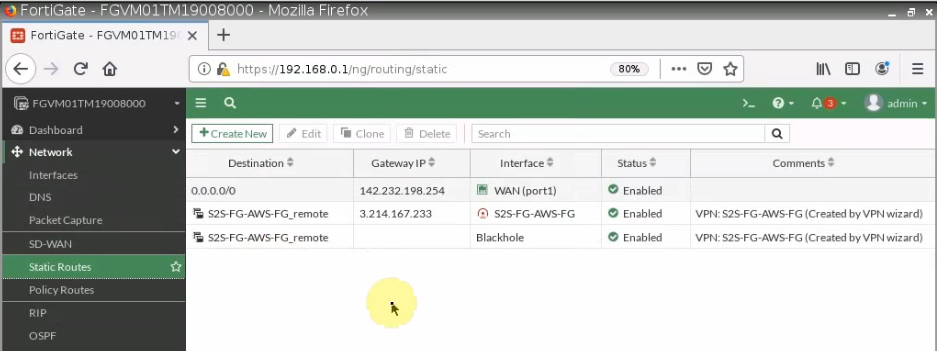
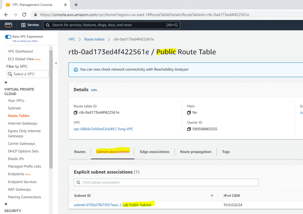
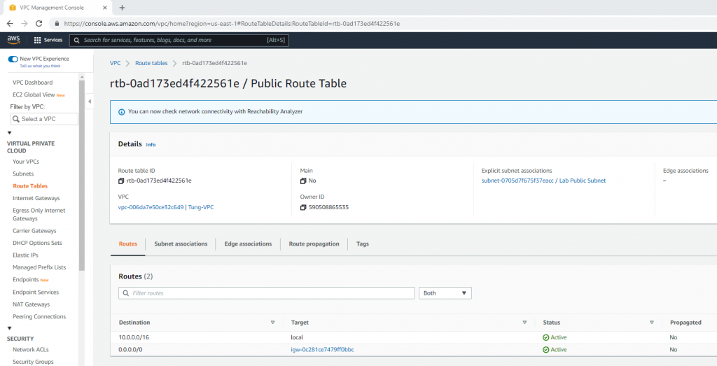
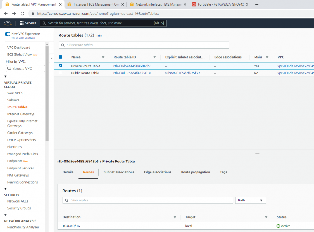
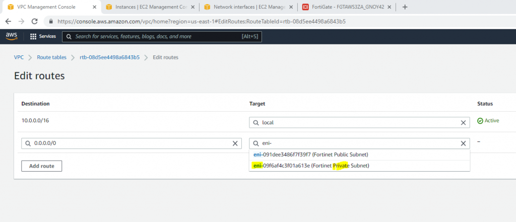
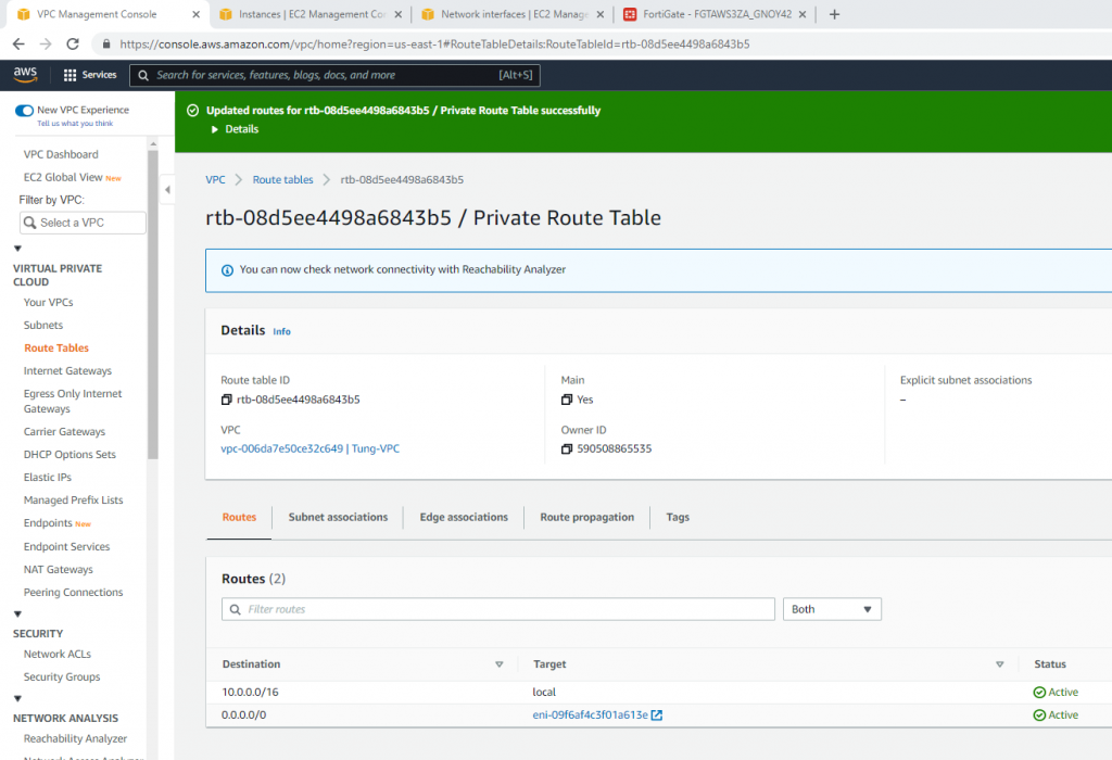
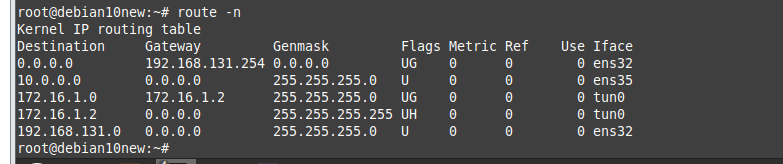
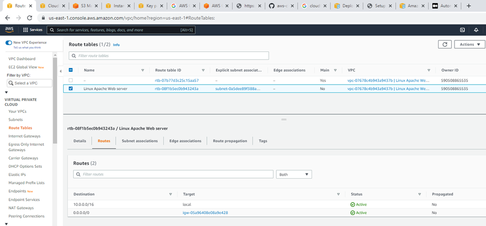
Route tables.
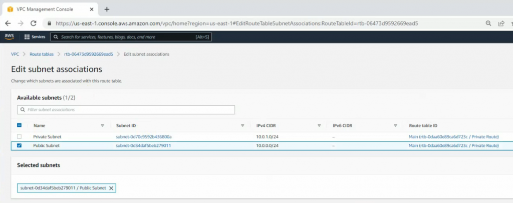
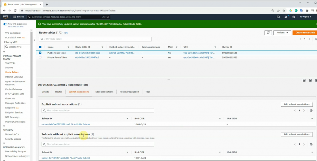
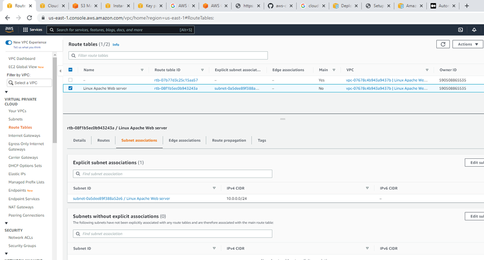
Subnet association.
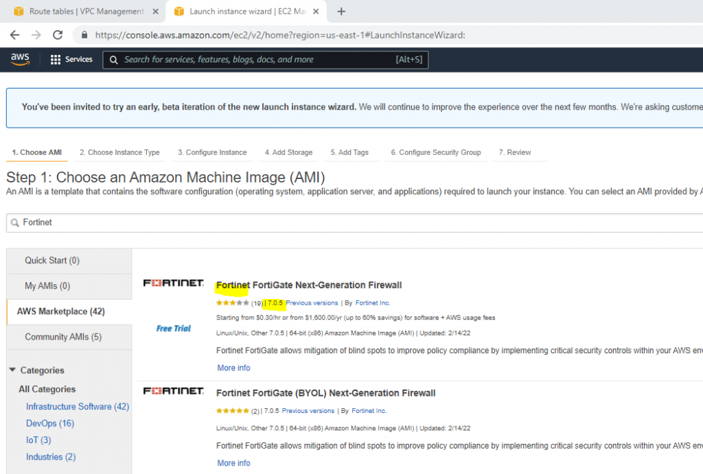
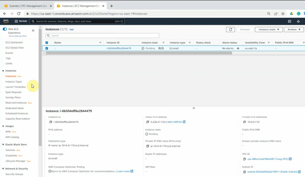
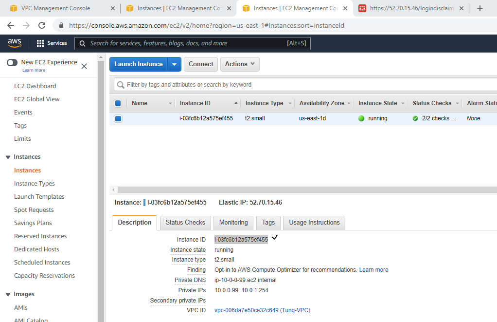
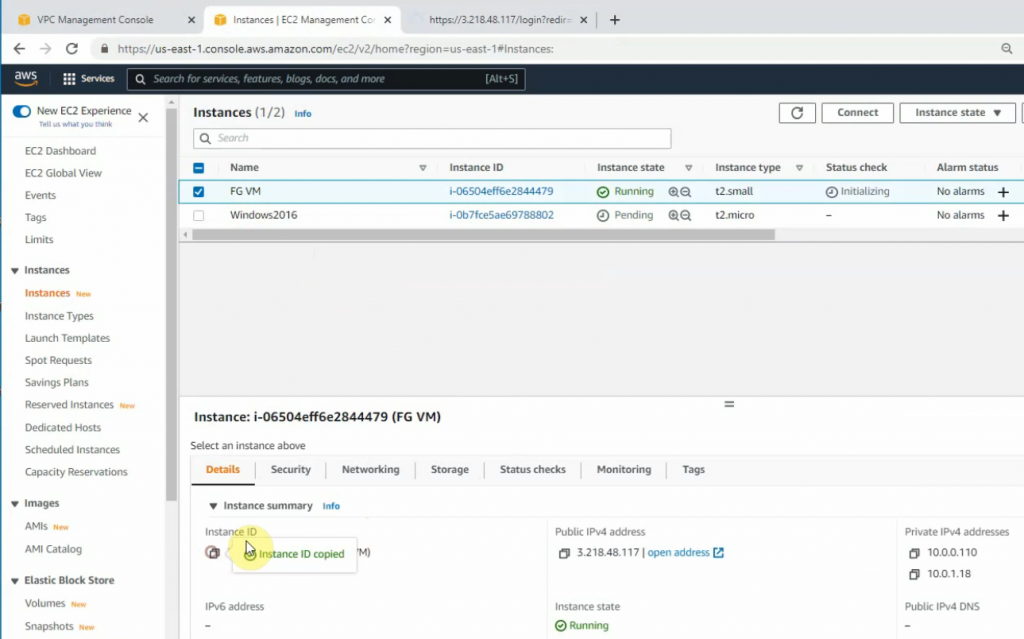
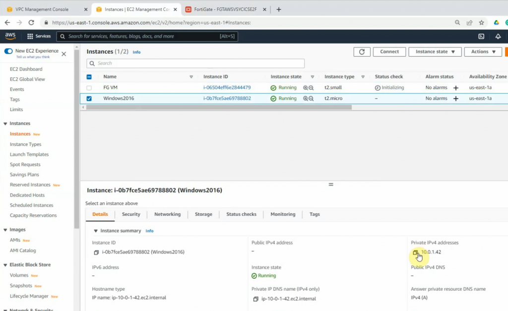
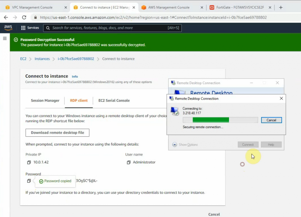
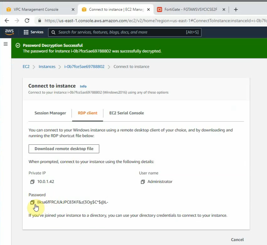
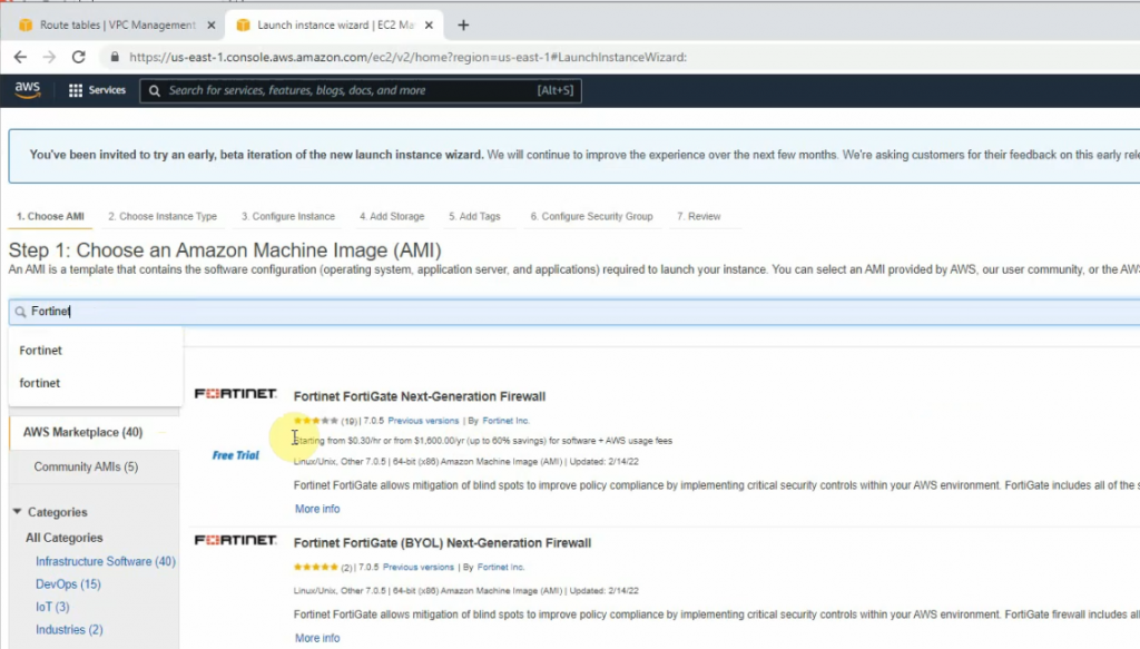
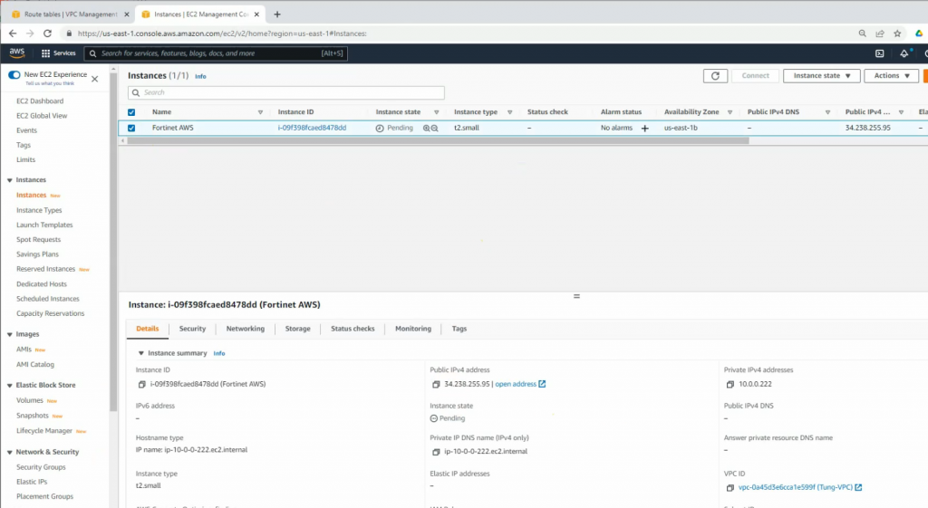
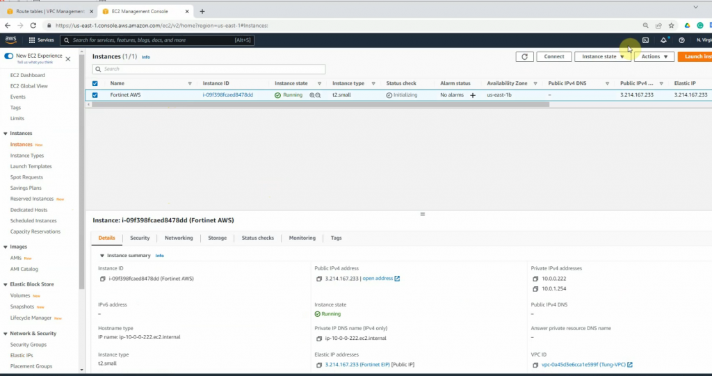
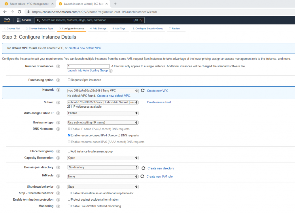
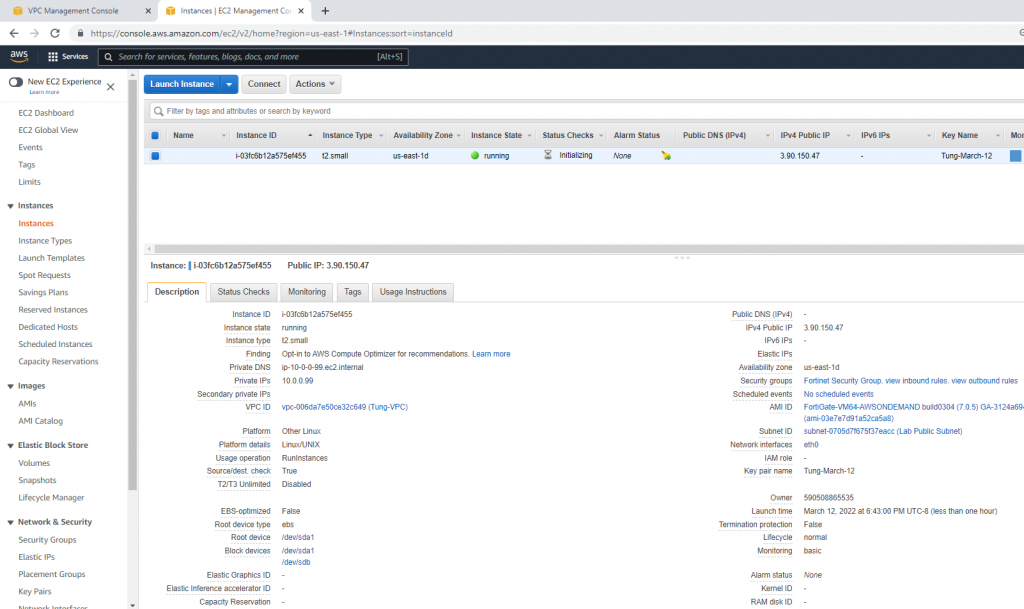
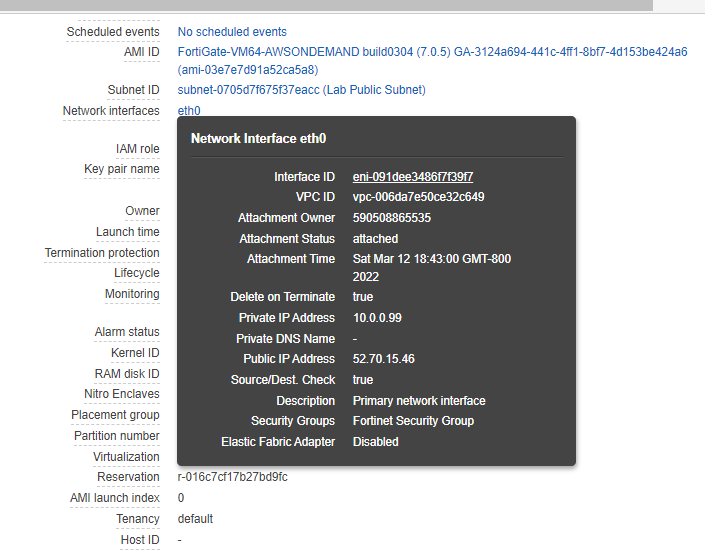
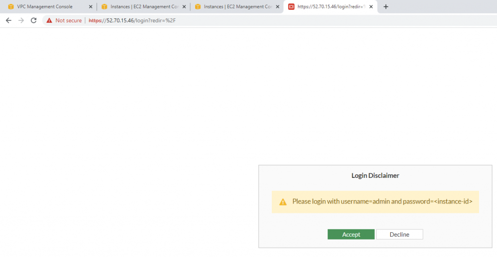
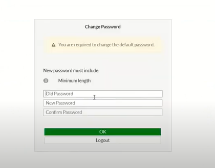
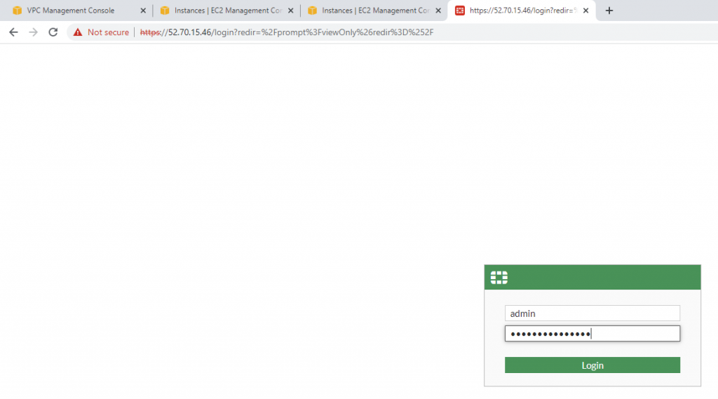
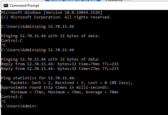
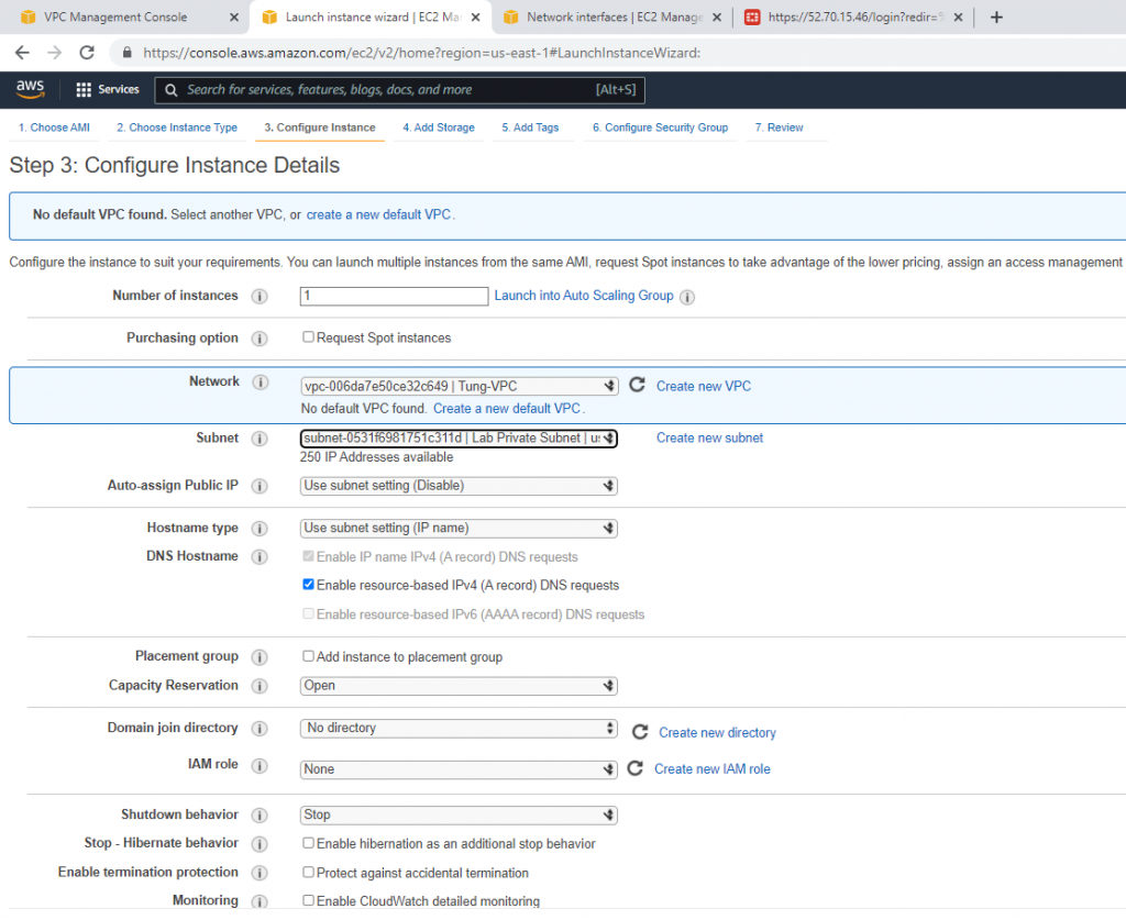
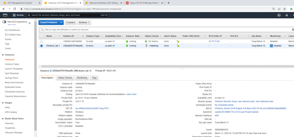
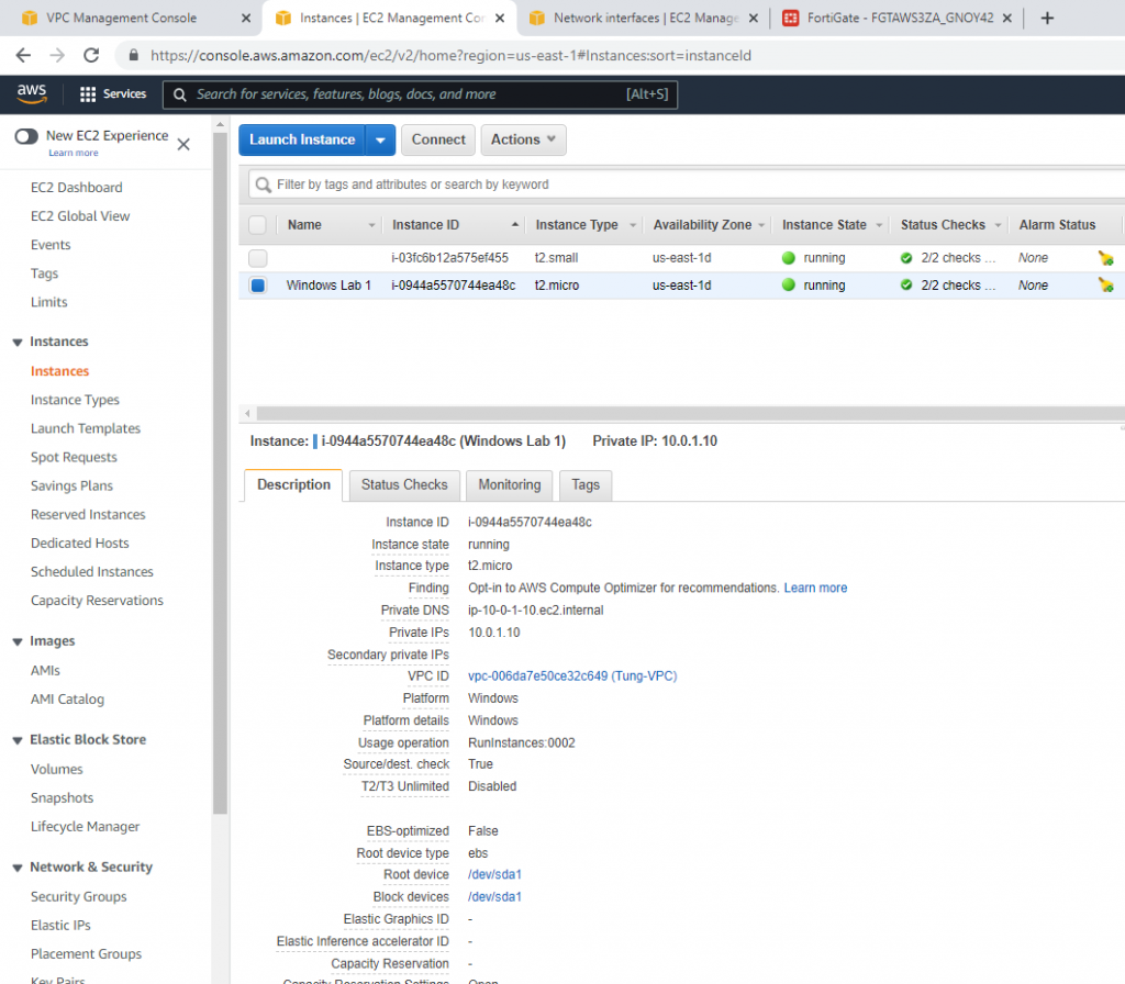
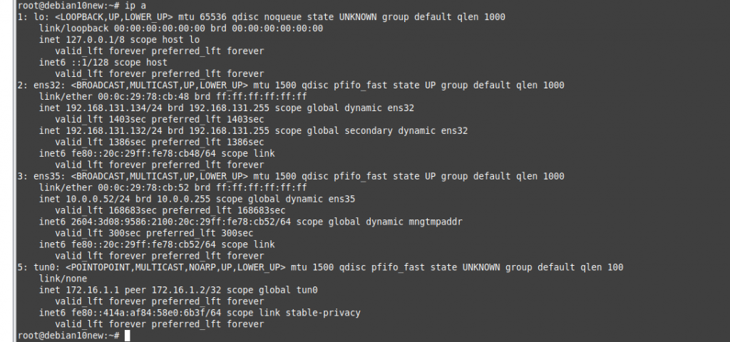
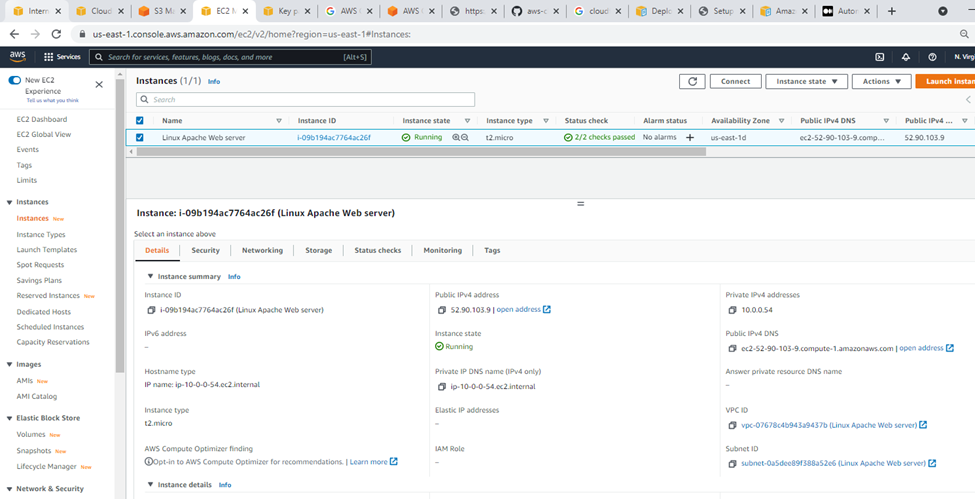
Linux instance.
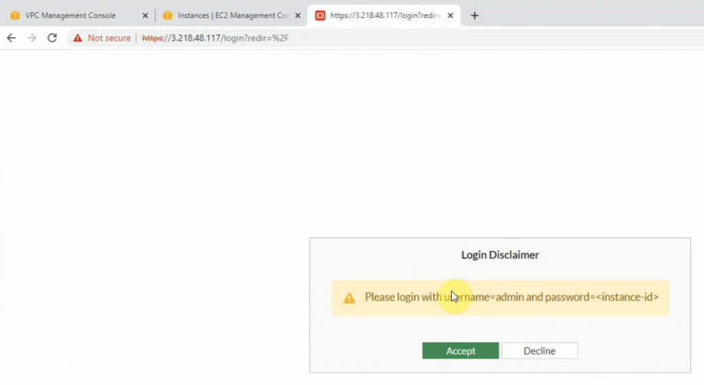
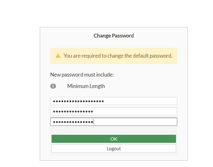
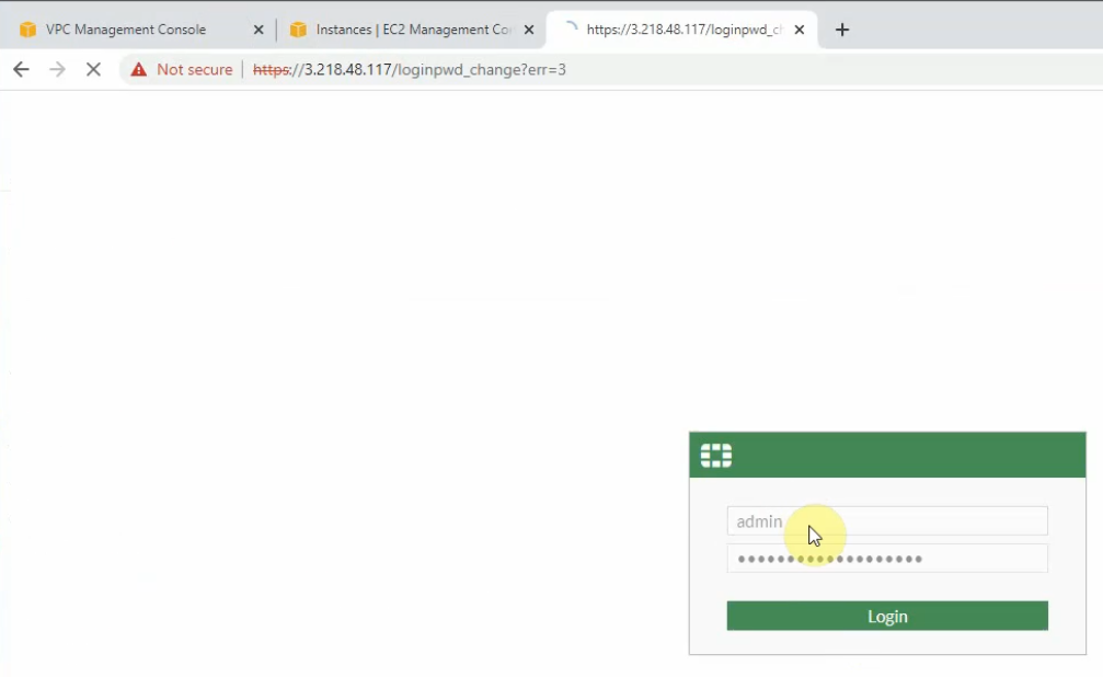
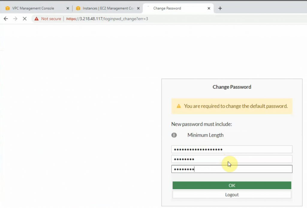
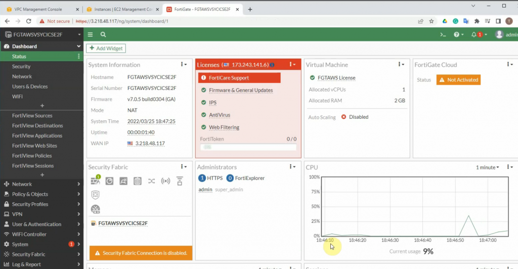
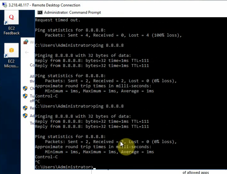
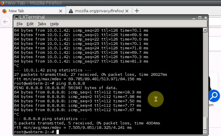
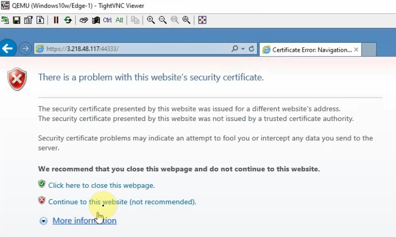
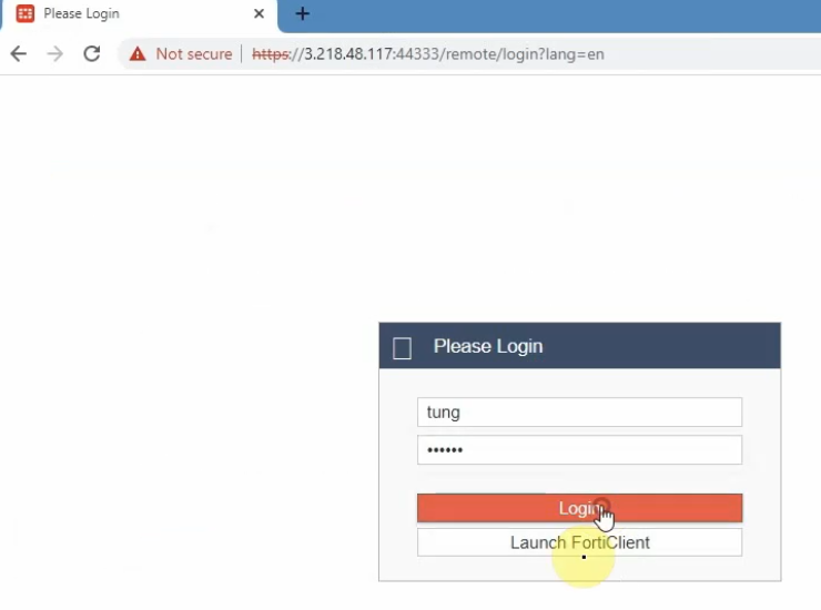
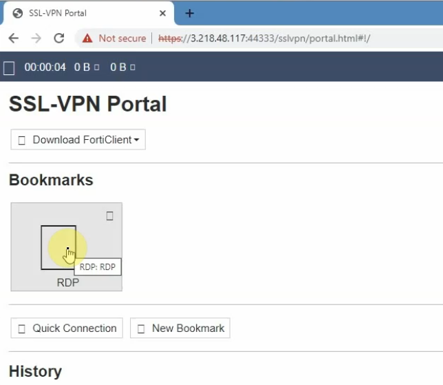
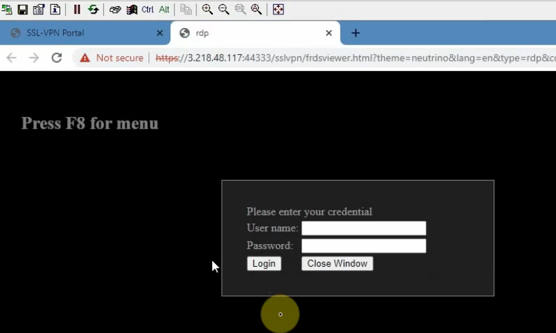
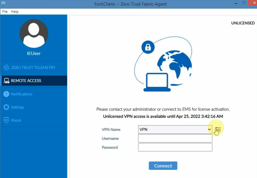
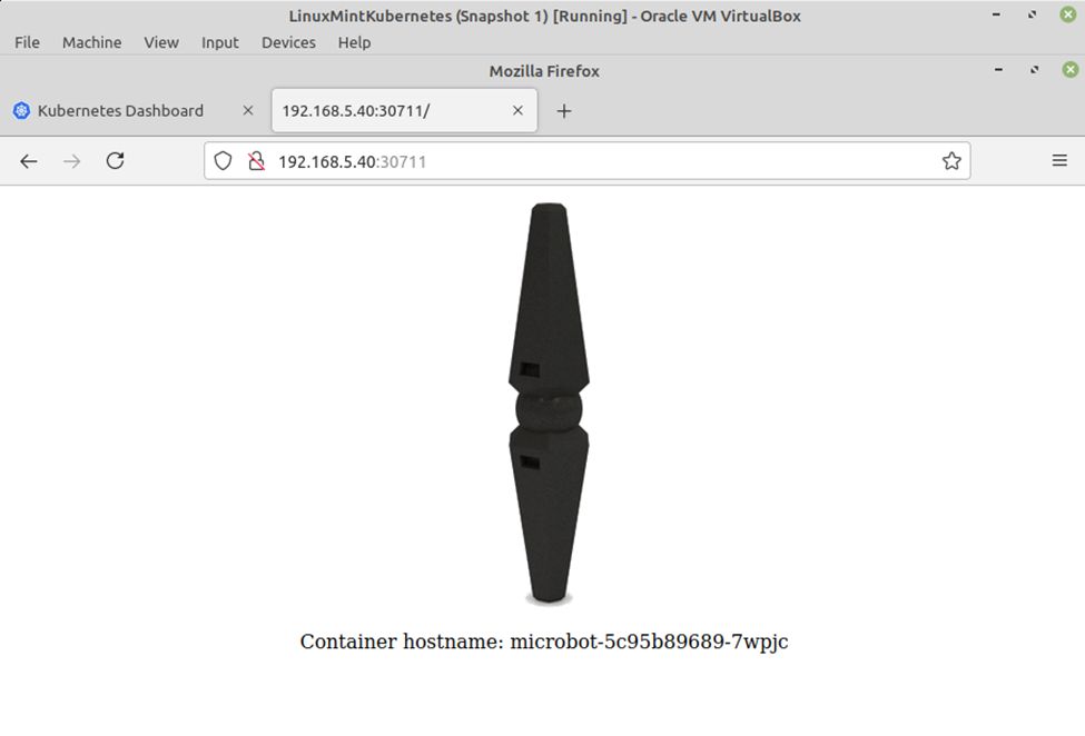
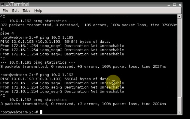
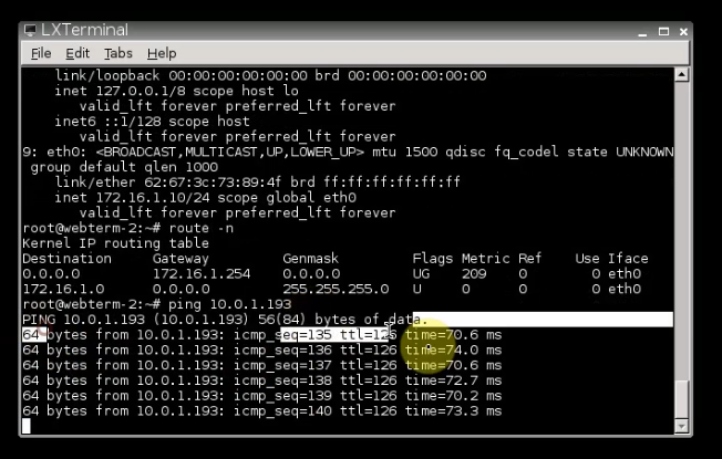
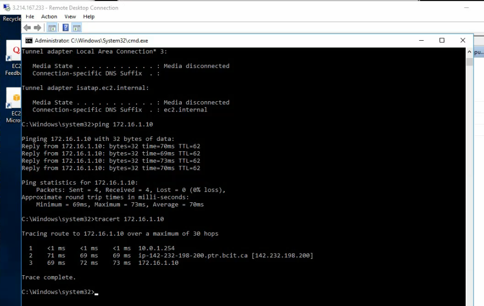
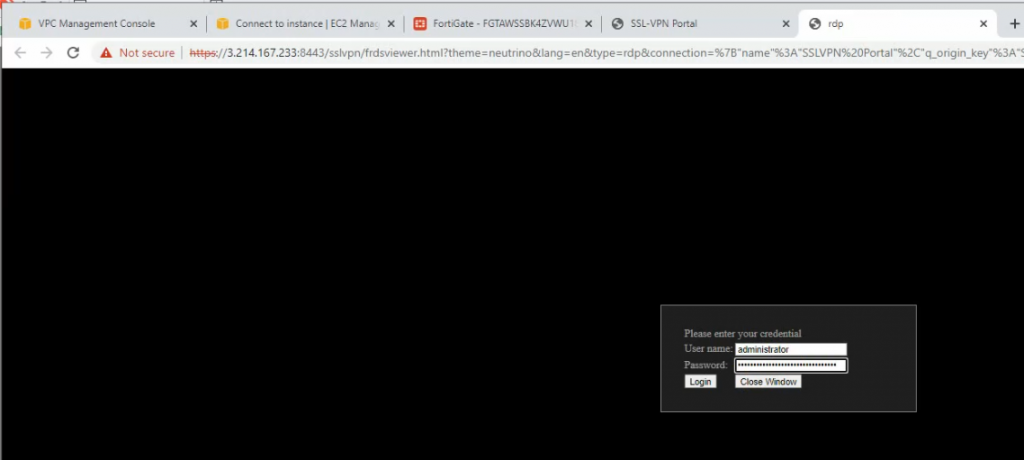
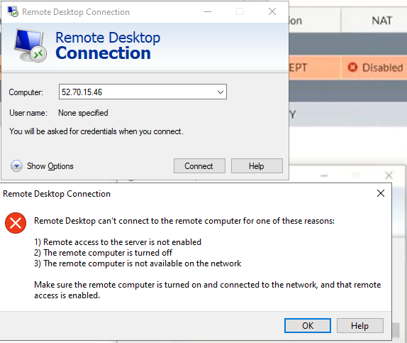
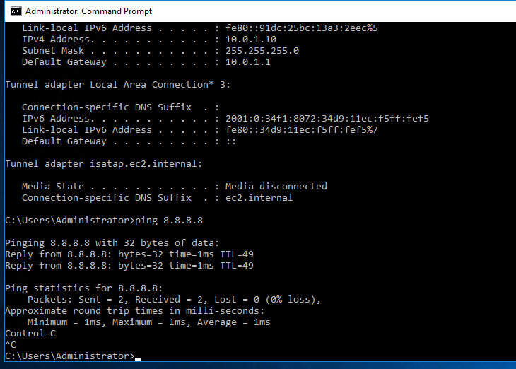
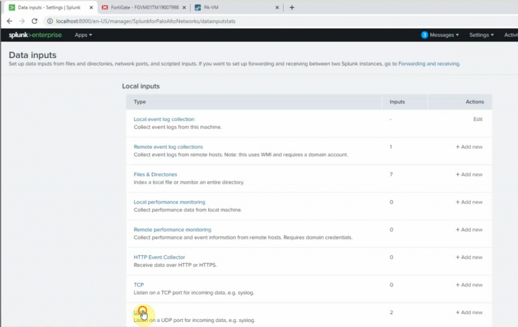
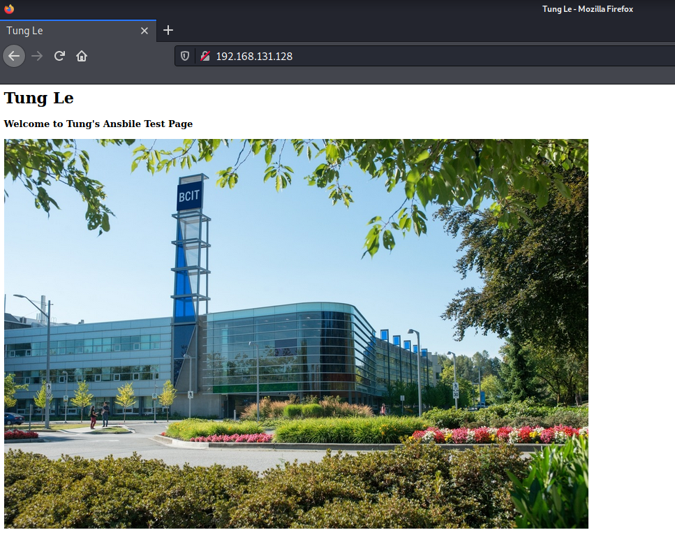
Access the website.
I have attached the short video demonstration in the following link.