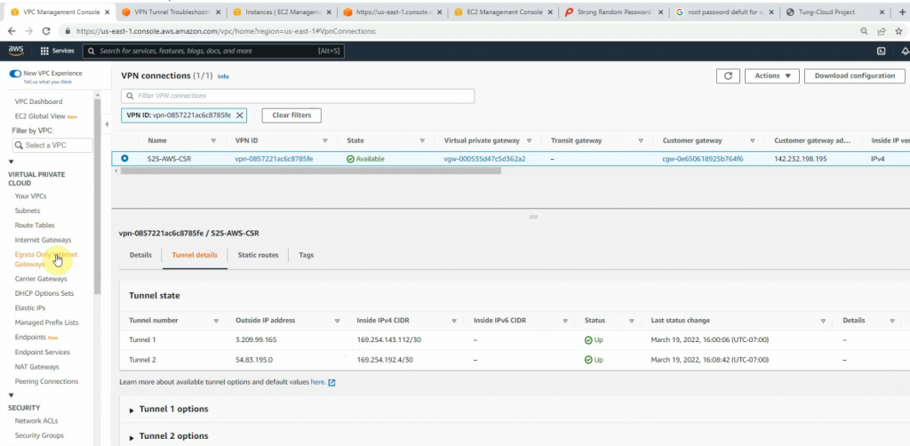
This is a diagram that is used to deploy this lab.
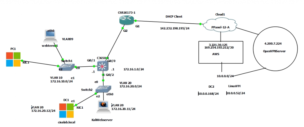
Create a new VPC with CIDR is 10.0.0.0/16. Then, create a new private subnet on AWS is 10.0.0.0/24.
Next, create a Customer gateway on AWS.


Create a site-to-site between AWS and Router CSR.


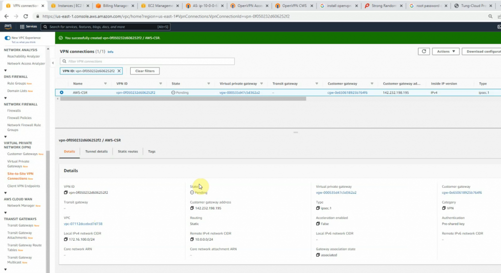
Click download configuration to configure on Cisco CSR.

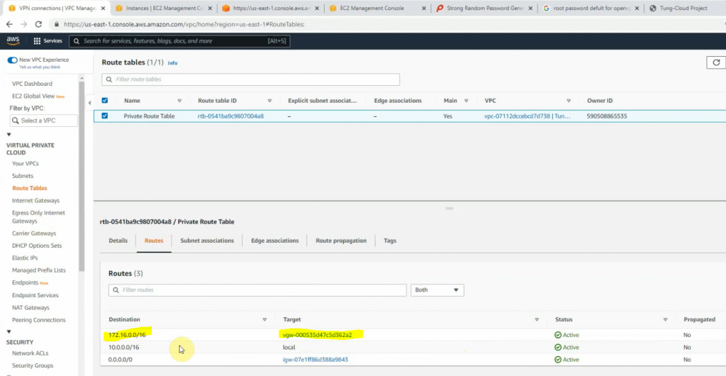
Add another route to Cisco CSR LAN subnets on AWS Private route table.
Configure CoreSW.
conf t
hostname CoreSW
ip routing
ip dhcp excluded-address 172.16.10.1 172.16.10.10
!
ip dhcp pool VLAN10
 network 172.16.10.0 255.255.255.0
 default-router 172.16.10.1
 dns-server 172.16.20.12

interface GigabitEthernet0/0
 no switchport
 ip address 172.16.1.1 255.255.255.0
!
interface GigabitEthernet0/1
 switchport trunk allowed vlan 10,20,99
 switchport trunk encapsulation dot1q
 switchport trunk native vlan 99
 switchport mode trunk
 negotiation auto
!
interface GigabitEthernet0/2
 switchport trunk allowed vlan 10,20,99
 switchport trunk encapsulation dot1q
 switchport trunk native vlan 99
 switchport mode trunk

interface Vlan10
 ip address 172.16.10.1 255.255.255.0
!
interface Vlan20
 ip address 172.16.20.1 255.255.255.0
!
router ospf 1
 router-id 1.1.1.1
 network 172.16.0.0 0.0.255.255 area 0
!
ip route 0.0.0.0 0.0.0.0 172.16.1.254
--
Configure VLAN
CoreSW(config)#vlan 10
CoreSW(config-vlan)#name PCs
CoreSW(config-vlan)#vlan 20
CoreSW(config-vlan)#name Servers
CoreSW(config-vlan)#vlan 99
CoreSW(config-vlan)#name Native
CoreSW(config-vlan)#do sh vlan bri

VLAN Name                             Status    Ports
---- -------------------------------- --------- -------------------------------
1    default                          active    Gi0/3, Gi1/0, Gi1/1, Gi1/2
                                                Gi1/3, Gi2/0, Gi2/1, Gi2/2
                                                Gi2/3, Gi3/0, Gi3/1, Gi3/2
                                                Gi3/3
10   PCs                              active
20   Servers                          active
99   Native                           active
Configure Cisco CSR.
interface GigabitEthernet1
 ip address dhcp
 ip nat outside
 negotiation auto
 no mop enabled
 no mop sysid
!
interface GigabitEthernet2
 ip address 172.16.1.254 255.255.255.0
 ip nat inside
 negotiation auto
 no mop enabled
 no mop sysid
router ospf 1
 router-id 3.3.3.3
 network 172.16.0.0 0.0.255.255 area 0
!
ip nat inside source list 1 interface GigabitEthernet1 overload
ip route 0.0.0.0 0.0.0.0 142.232.198.254
Next, opens the file that you have downloaded on AWS, then copy and paste its configuration to Cisco CSR to create both IPSEC VPN site-to-site IKEv2 tunnels on the Router.
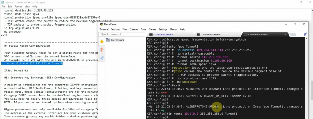
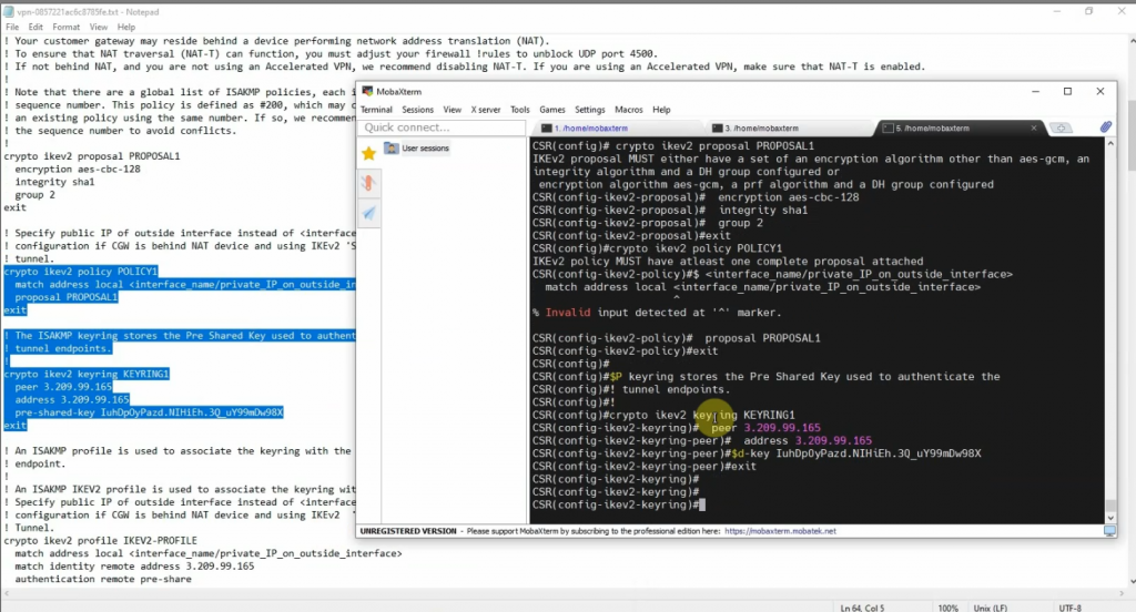
Cisco CSR configuration
-------
crypto ikev2 proposal PROPOSAL1
 encryption aes-cbc-128
 integrity sha1
 group 2
!
crypto ikev2 policy POLICY1
 match address local 142.232.198.195
 proposal PROPOSAL1
!
crypto ikev2 keyring KEYRING1
 peer 3.209.99.165
  address 3.209.99.165
  pre-shared-key IuhDpOyPazd.NIHiEh.3Q_uY99mDw98X
 !
 peer 54.83.195.0
  address 54.83.195.0 255.255.255.0
  pre-shared-key tlDEo5uQkac9zzMt3s.kgU6ARGma5Cq8
 !

!crypto ikev2 profile IKEV2-PROFILE
 match address local 142.232.198.195
 match identity remote address 3.209.99.165 255.255.255.255
 match identity remote address 54.83.195.0 255.255.255.0
 authentication remote pre-share
 authentication local pre-share
 keyring local KEYRING1
 lifetime 28800
 dpd 10 10 on-demand
crypto isakmp keepalive 10 10
!
crypto ipsec security-association replay window-size 128
!
crypto ipsec transform-set ipsec-prop-vpn-0857221ac6c8785fe-0 esp-aes esp-sha-hmac
 mode tunnel
crypto ipsec transform-set ipsec-prop-vpn-0857221ac6c8785fe-1 esp-aes esp-sha-hmac
 mode tunnel
crypto ipsec df-bit clear
!
crypto ipsec profile ipsec-vpn-0857221ac6c8785fe-0
 set transform-set ipsec-prop-vpn-0857221ac6c8785fe-0
 set pfs group2
 set ikev2-profile IKEV2-PROFILE
!
crypto ipsec profile ipsec-vpn-0857221ac6c8785fe-1
 set transform-set ipsec-prop-vpn-0857221ac6c8785fe-1
 set pfs group2
 set ikev2-profile IKEV2-PROFILE
interface Tunnel1
 ip address 169.254.143.114 255.255.255.252
 ip tcp adjust-mss 1379
 tunnel source 142.232.198.195
 tunnel mode ipsec ipv4
 tunnel destination 3.209.99.165
 tunnel protection ipsec profile ipsec-vpn-0857221ac6c8785fe-0
 ip virtual-reassembly
!
interface Tunnel2
 ip address 169.254.192.6 255.255.255.252
 ip tcp adjust-mss 1379
 tunnel source 142.232.198.195
 tunnel mode ipsec ipv4
 tunnel destination 54.83.195.0
 tunnel protection ipsec profile ipsec-vpn-0857221ac6c8785fe-1
 ip virtual-reassembly
!
interface GigabitEthernet1
 ip address dhcp
 ip nat outside
 negotiation auto
 no mop enabled
 no mop sysid
!
interface GigabitEthernet2
 ip address 172.16.1.254 255.255.255.0
 ip nat inside
 negotiation auto
 no mop enabled
 no mop sysid
router ospf 1
 router-id 3.3.3.3
 network 172.16.0.0 0.0.255.255 area 0
!
ip nat inside source list 1 interface GigabitEthernet1 overload
ip route 0.0.0.0 0.0.0.0 142.232.198.254
ip route 10.0.0.0 255.255.255.0 Tunnel1
ip route 10.0.0.0 255.255.255.0 Tunnel2
!
ip access-list standard 1
 10 permit any
show CSR interfaces.CSR# sh ip int brief
Interface IP-Address OK? Method Status Protocol
GigabitEthernet1 142.232.198.195 YES DHCP up up
GigabitEthernet2 172.16.1.254 YES manual up up
GigabitEthernet3 unassigned YES unset administratively down down
GigabitEthernet4 unassigned YES unset administratively down down
Tunnel1 169.254.143.114 YES manual up up
Tunnel2 169.254.192.6 YES manual up up
show ip ospf neighbor

show ip route

show crypt ikev2 sa

show crypto ipsec sa

show crypto ipsec sa

Pings Linux instance on AWS from a machine on CSR LAN subnet.


Pings a Windows machine on CSR LAN subnet from the Linux instance on AWS.

Both tunnels are up on AWS and CSR Router.
