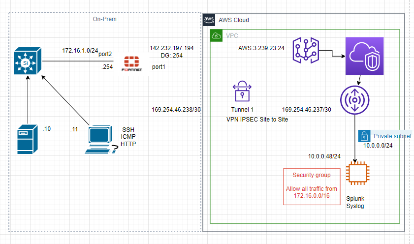
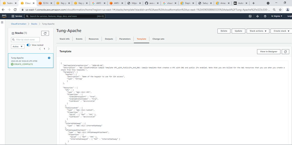
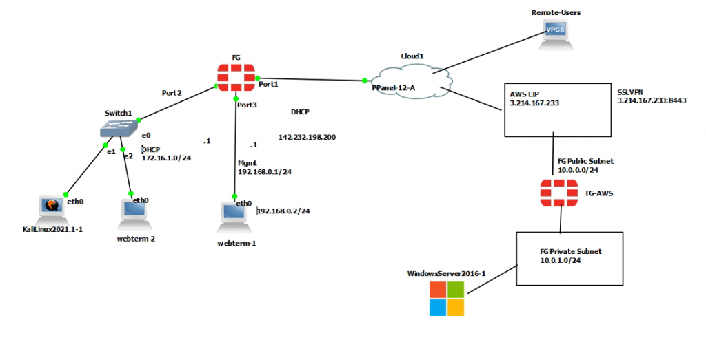
This is a diagram that I have used for this demonstration.
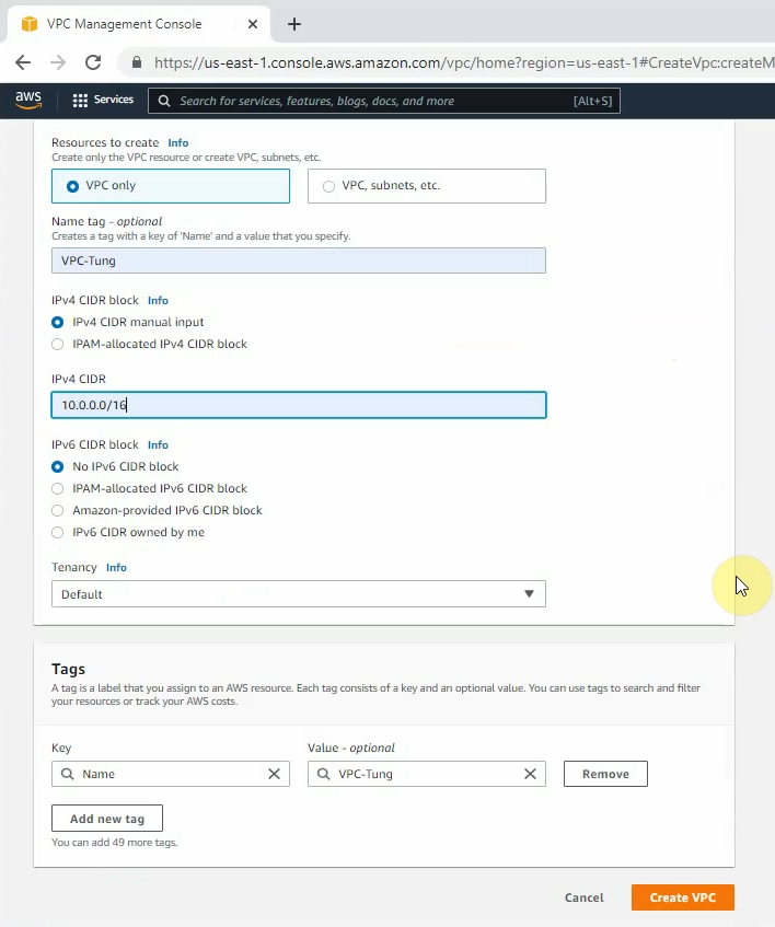
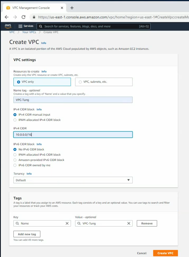
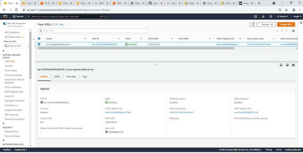
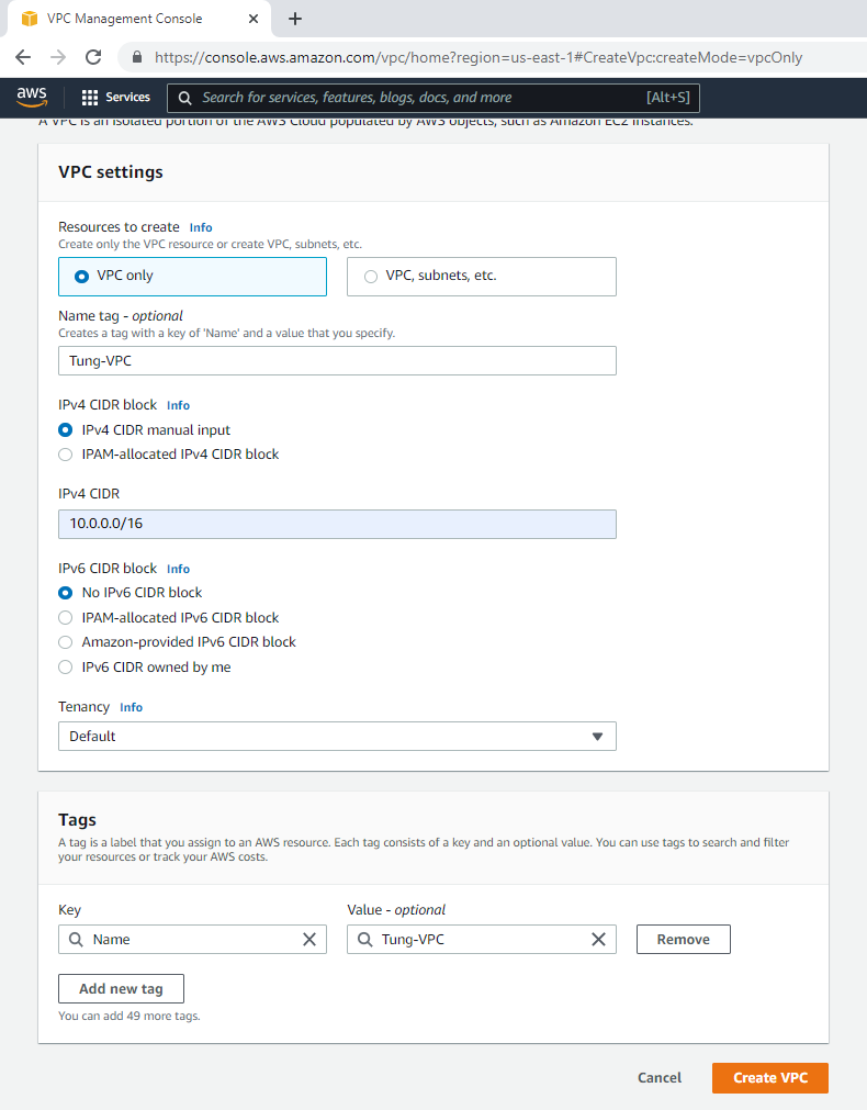
Create your VPC.
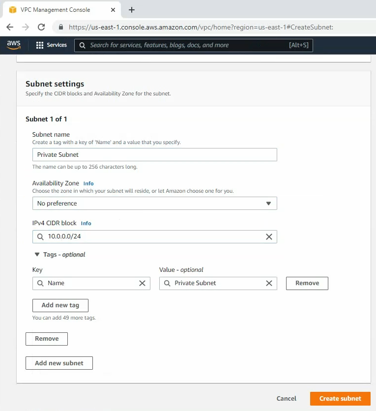
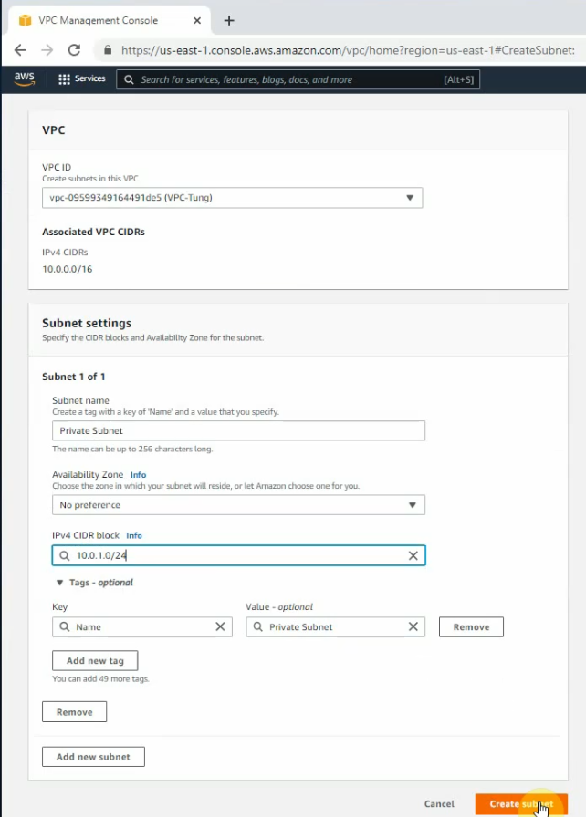
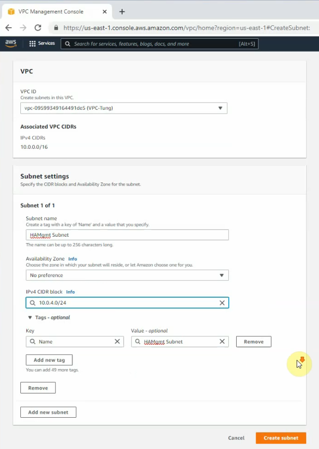
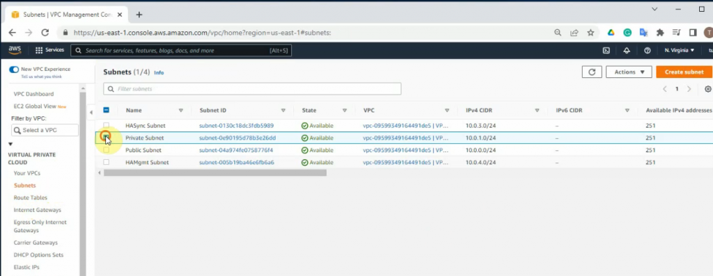
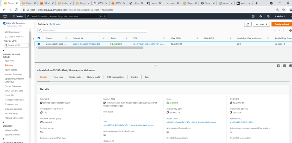
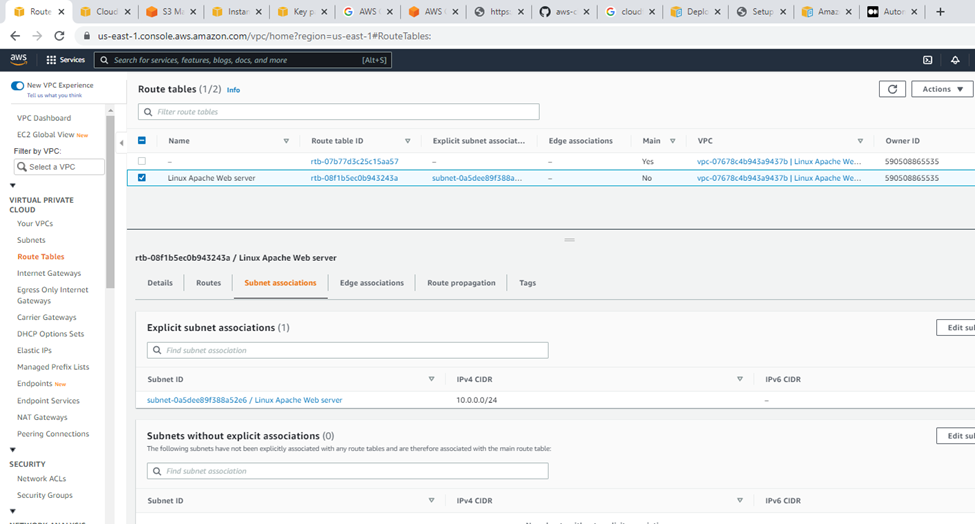
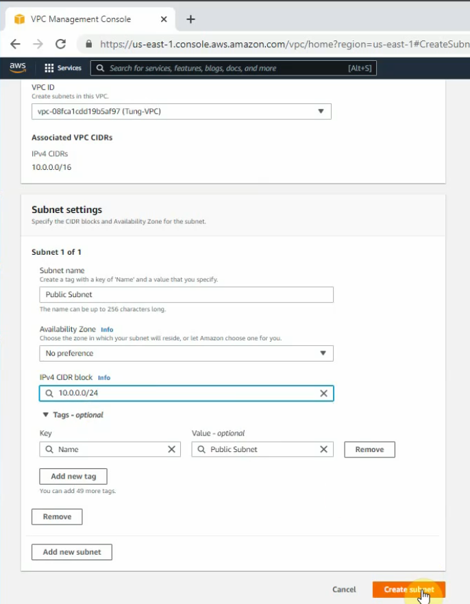
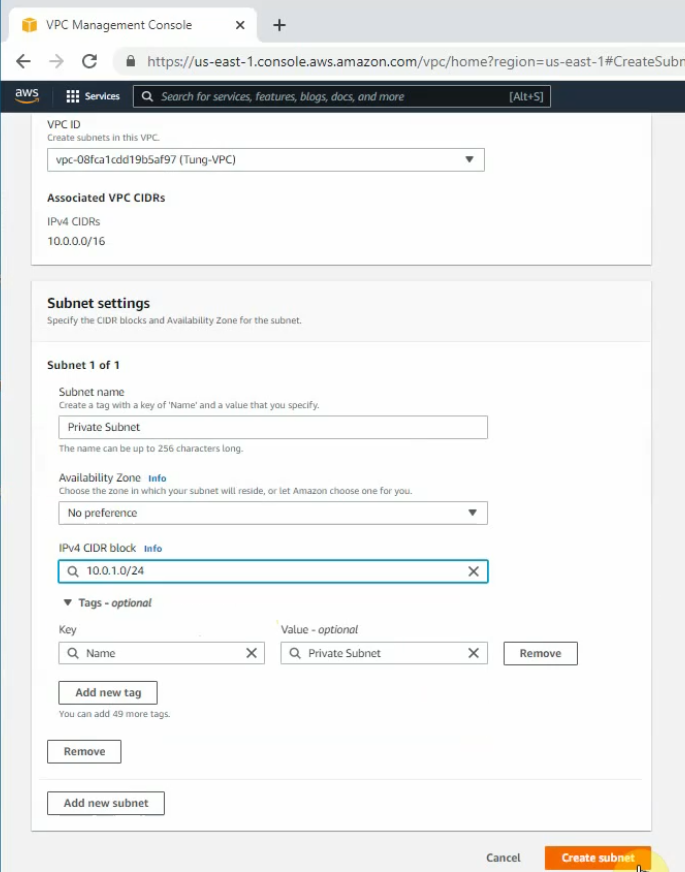
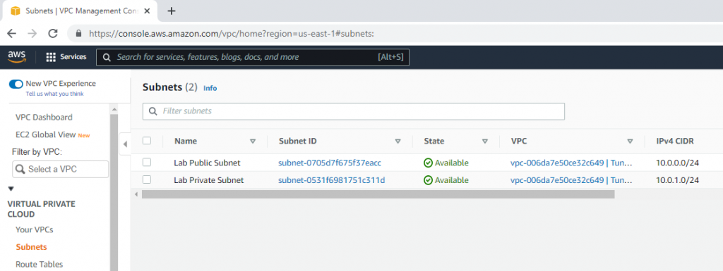
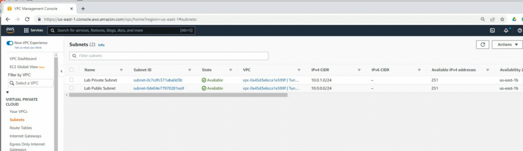
Create a private subnet.
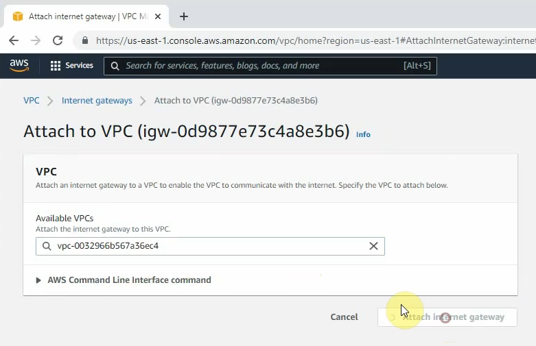
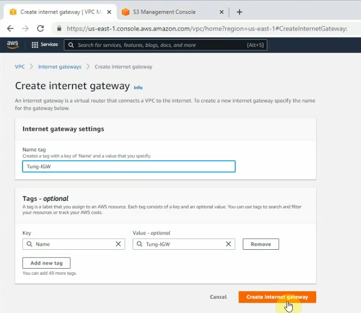
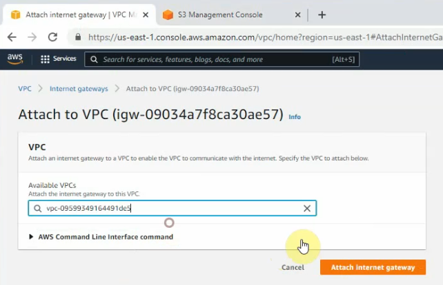
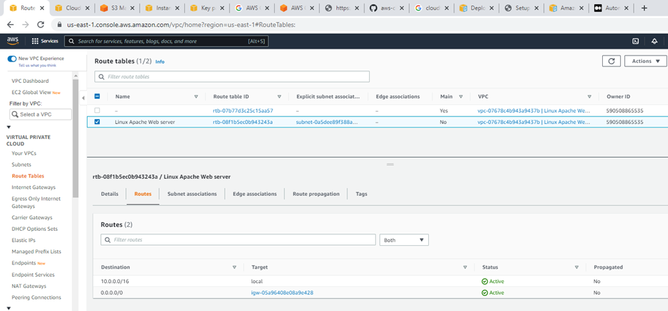
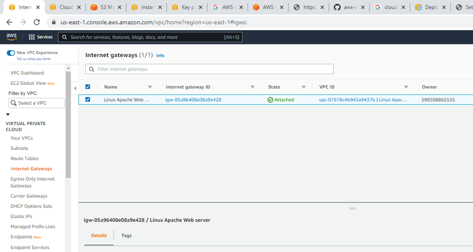
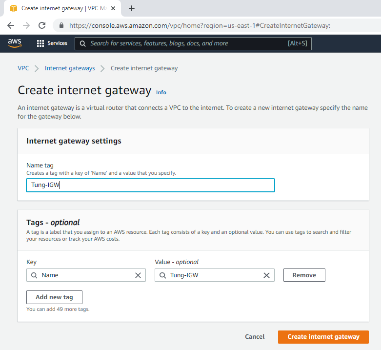
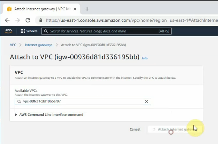
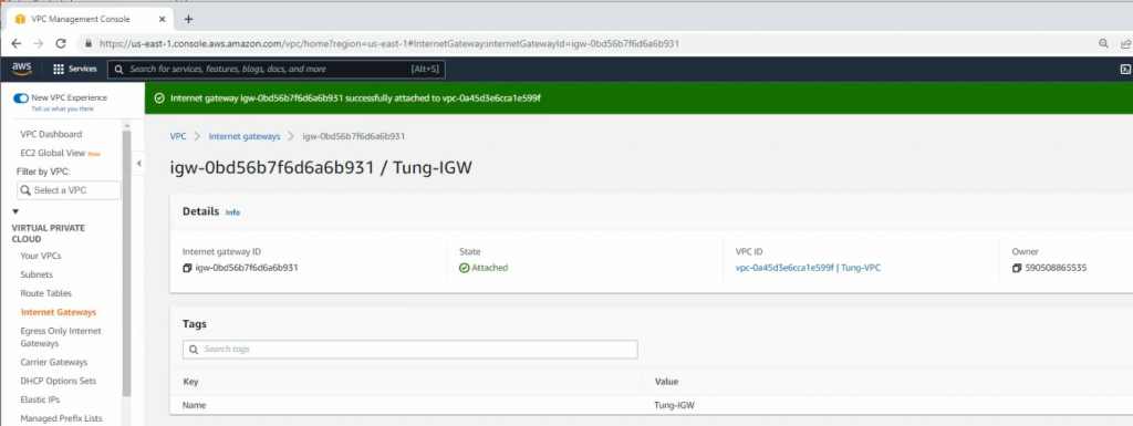
Create a new Internet Gateway and attach it to your VPC.
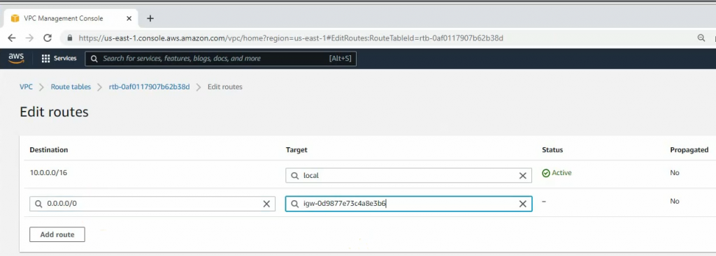
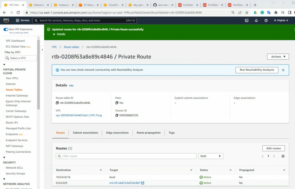
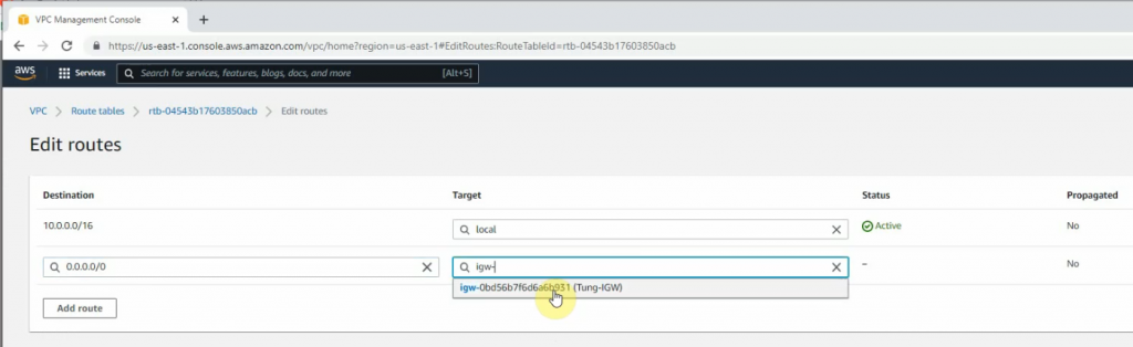
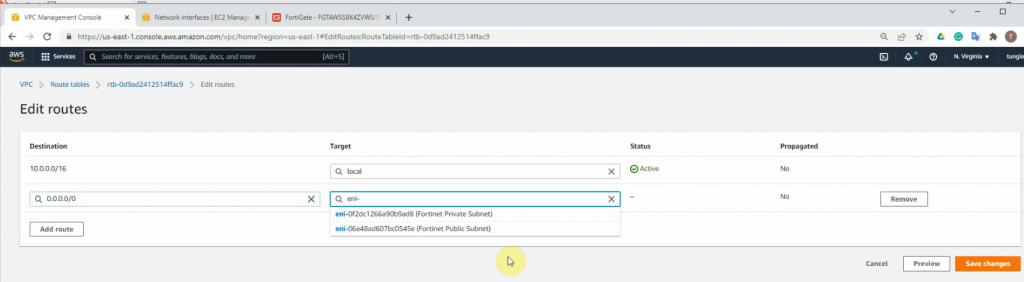
Create a new route to 0.0.0.0/0 to your Internet gateway.
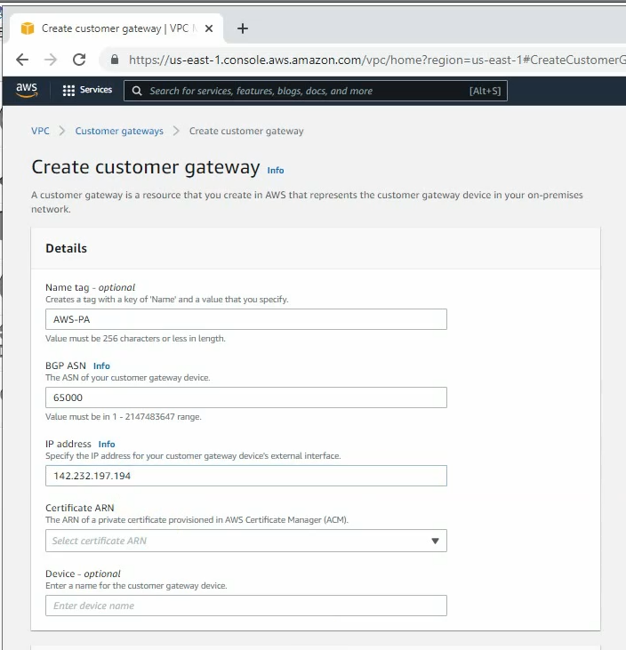
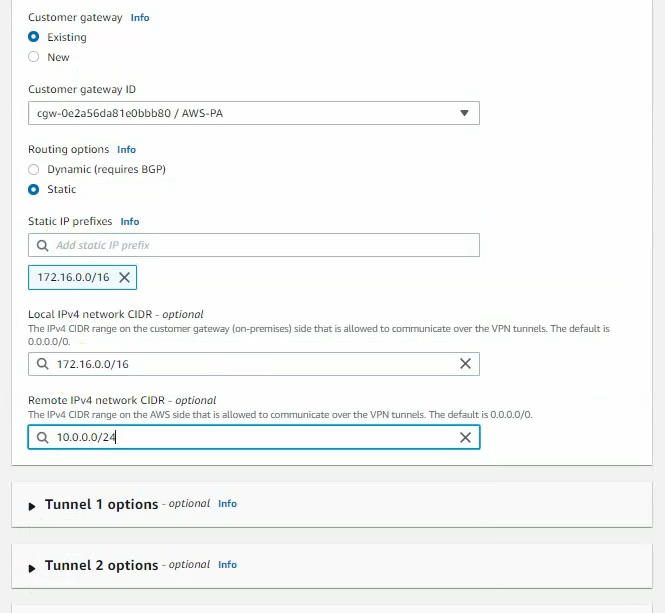
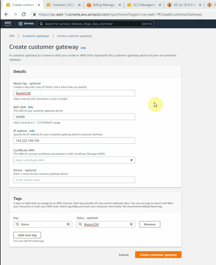
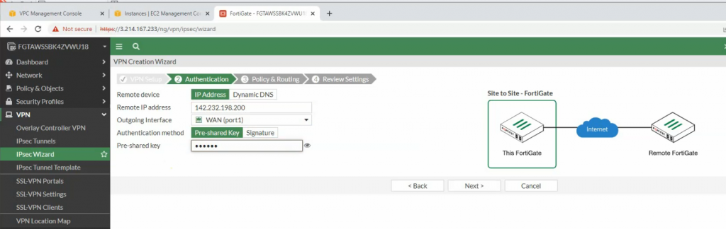
Create a new Customer gateway with the public IP address of FortiGate.
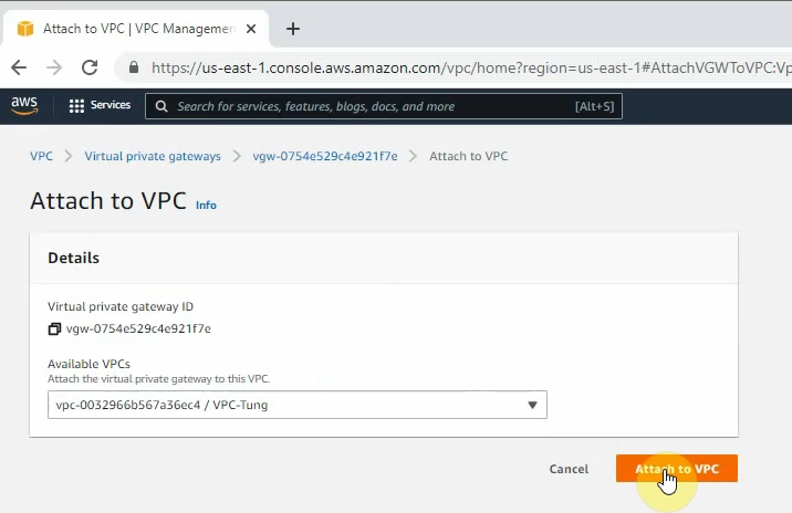
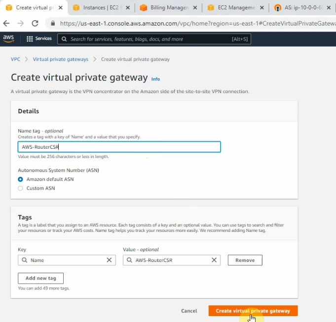
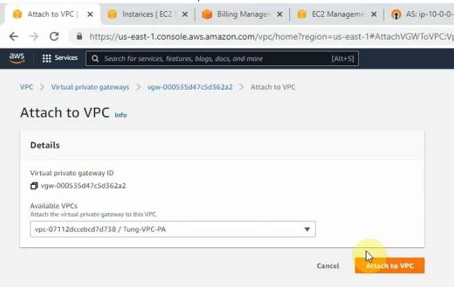
Create a new Virtual Private Gateway and attach it to your VPC.
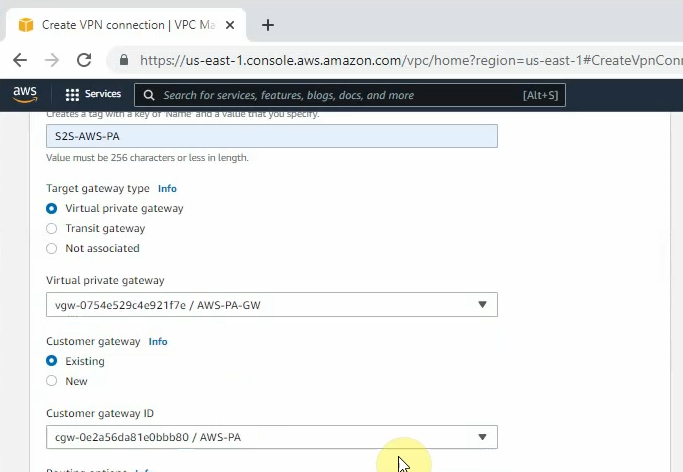
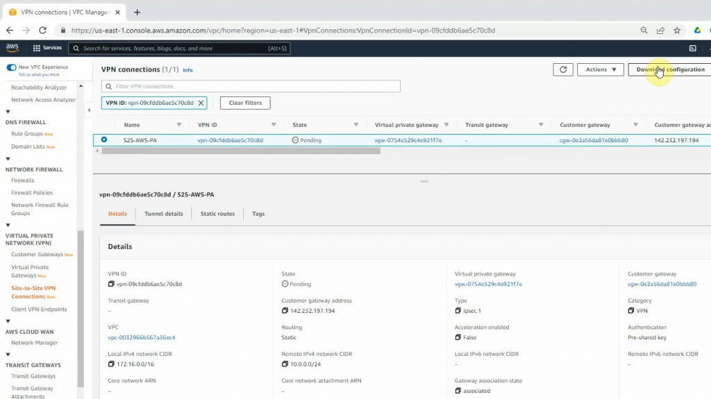
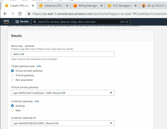
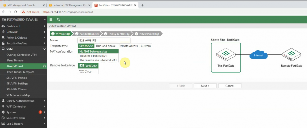
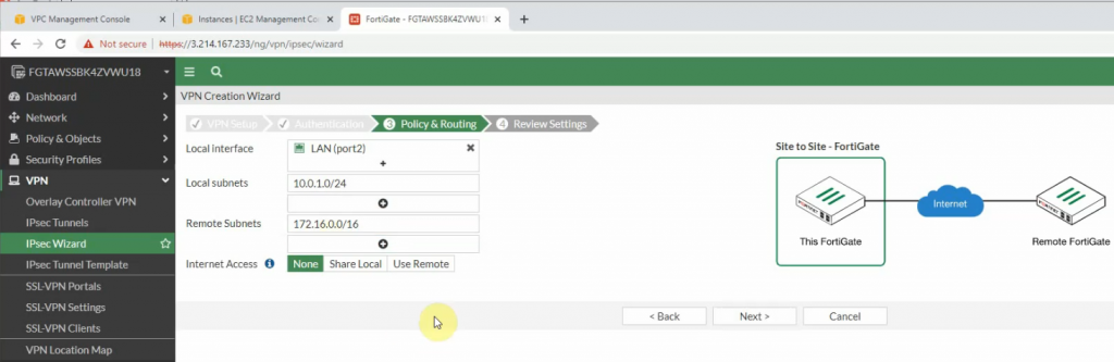
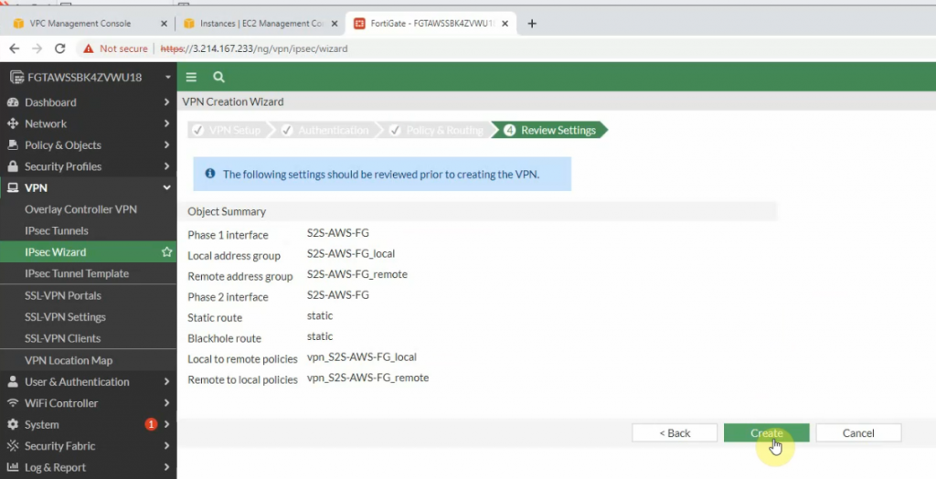
Create a new VPN site-to-site.
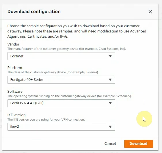
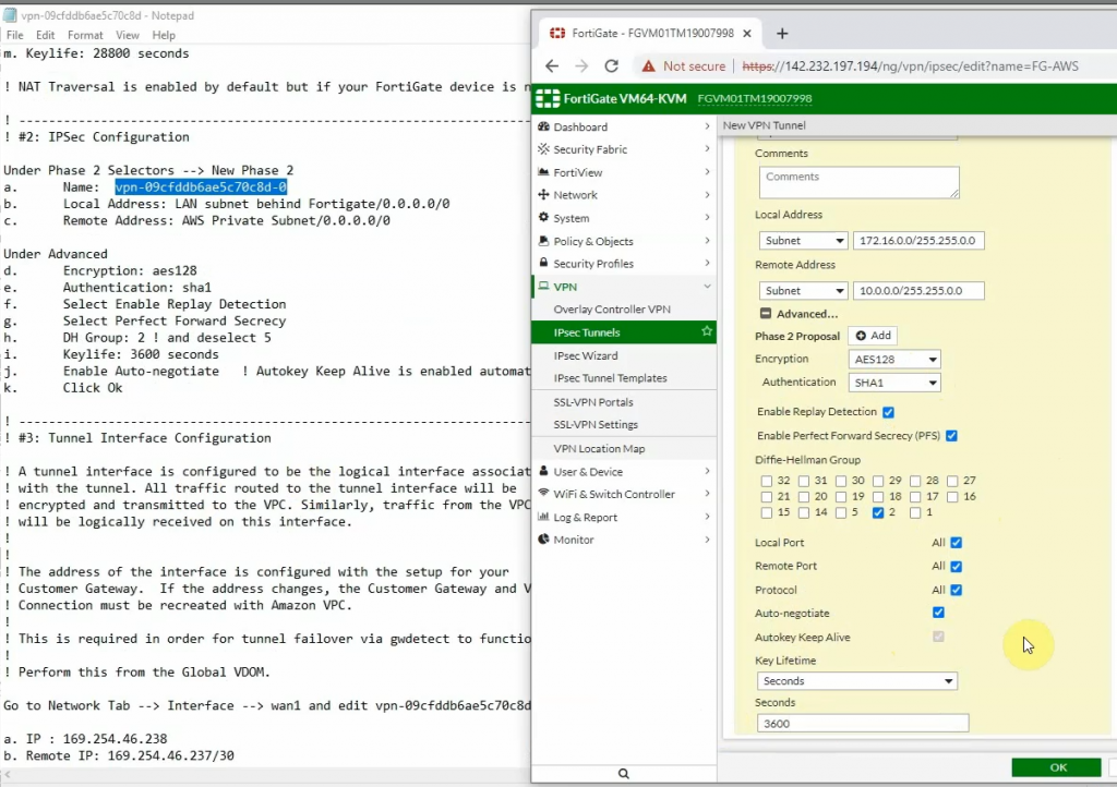
Click Download Configuration to configure on your FortiGate.
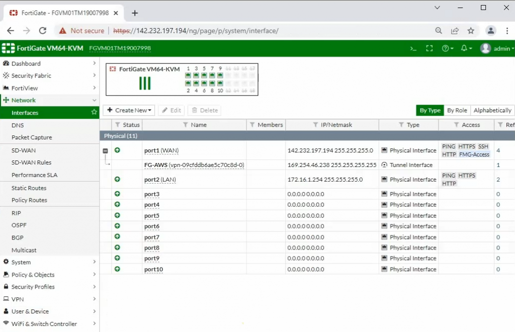
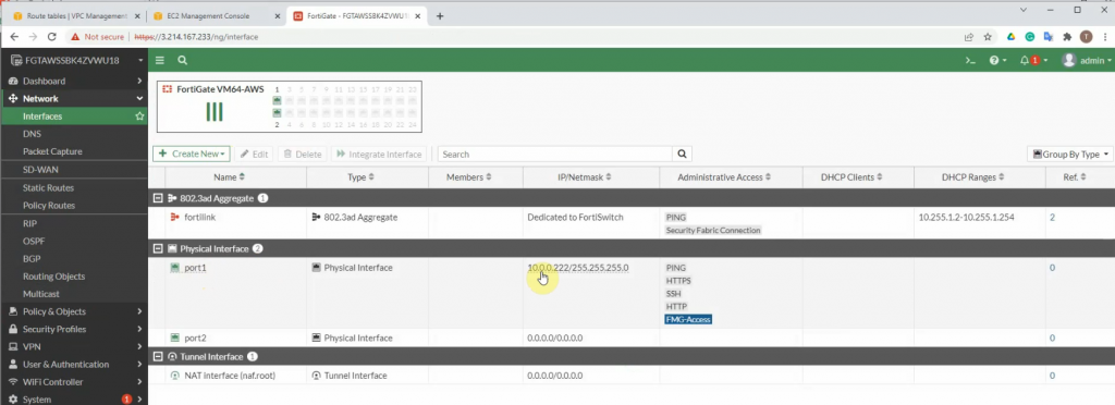
Log into FortiGate.
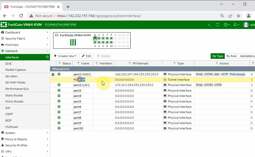
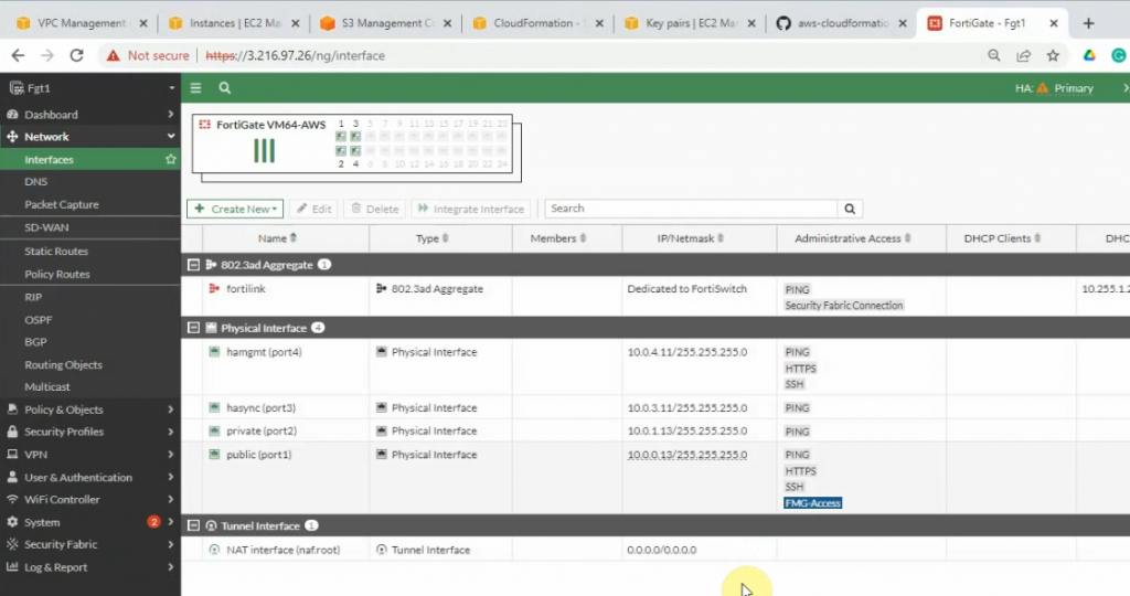
Interfaces.
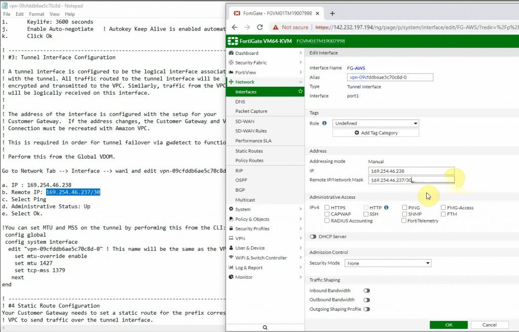
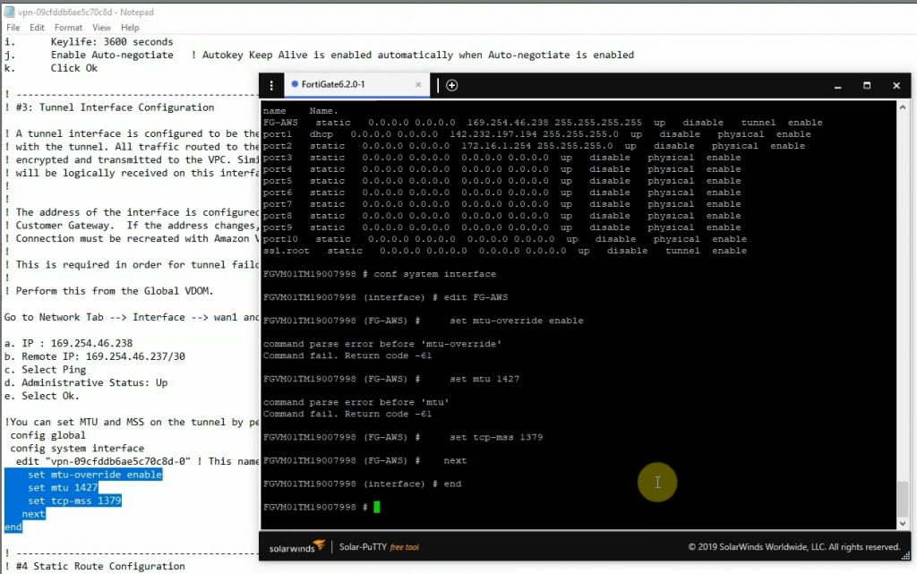
Copies these commands and pastes them into FortiGate. Notes the set “mtu 1427” and set “mtu-override enable” does not available on FortiGate 6.2
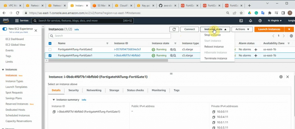
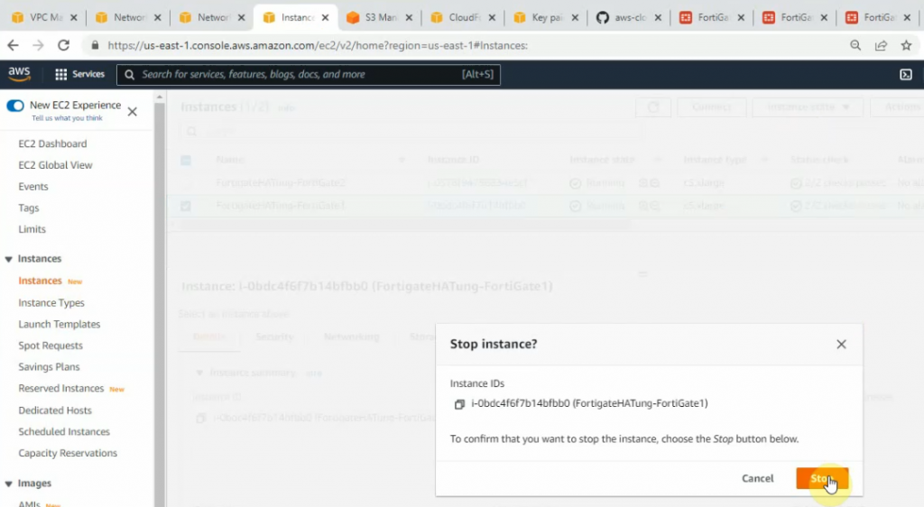
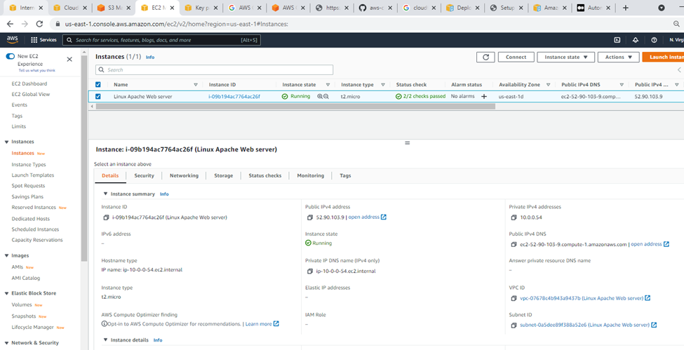
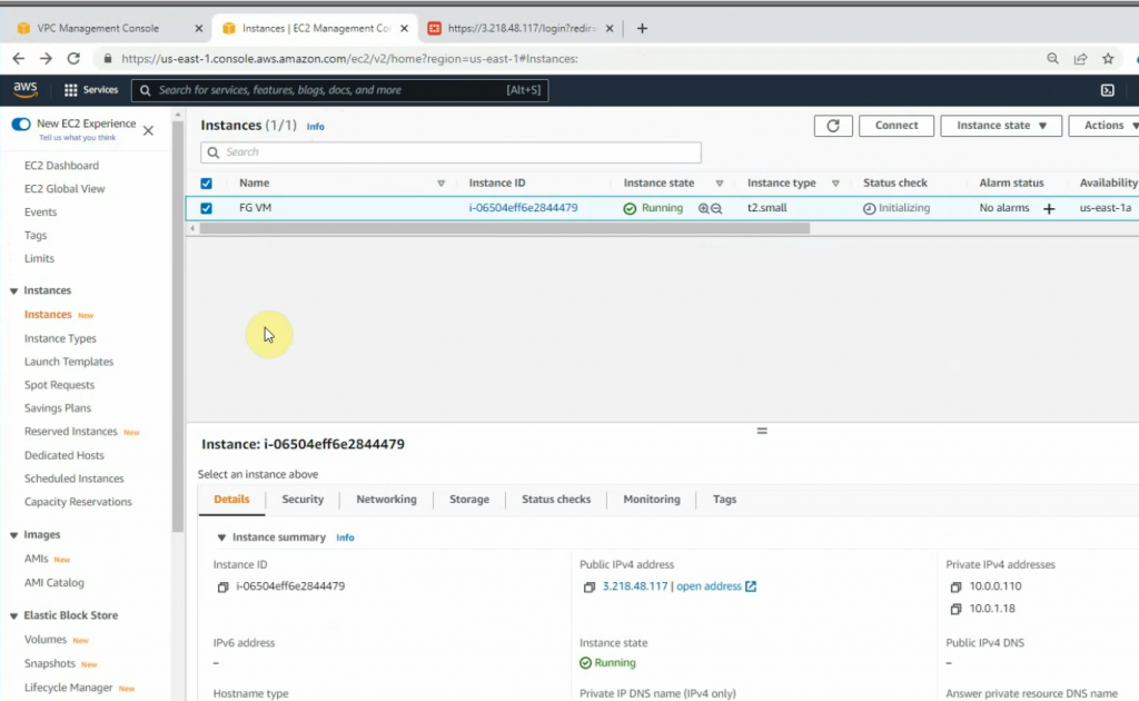
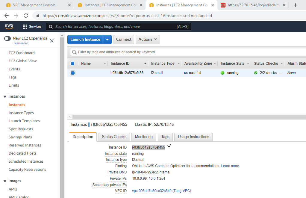
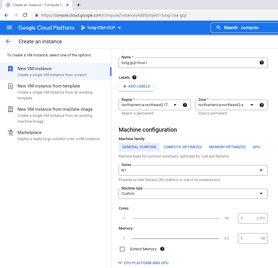
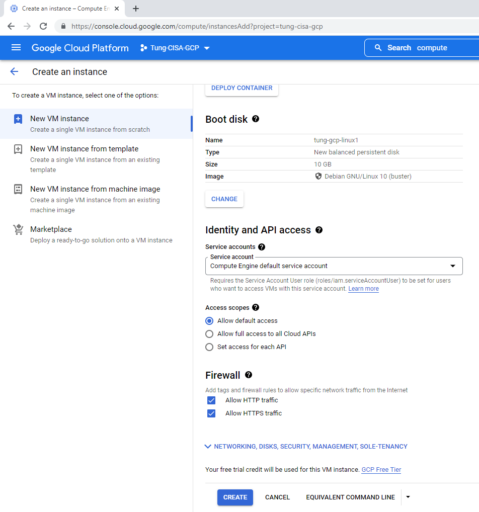
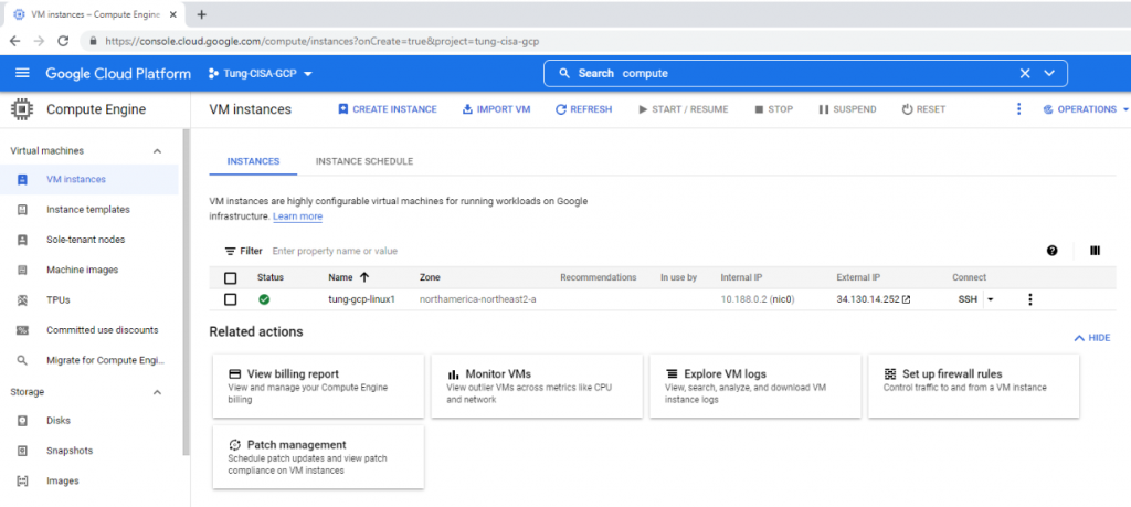
Back to AWS and launch a new Linux VM instance. This machine is used to test VPN site-to-site.
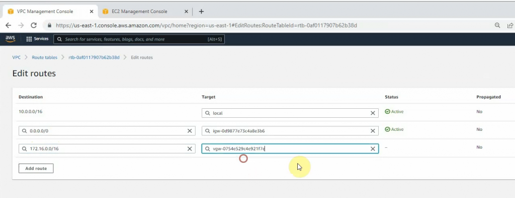
Configure a new static route to allow LAN subnets on AWS to access LAN subnets on FortiGate.
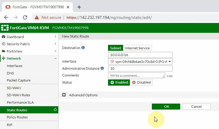
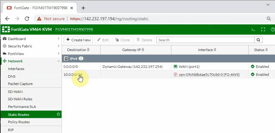
On FortiGate, configure a new static route to AWS LAN subnets.
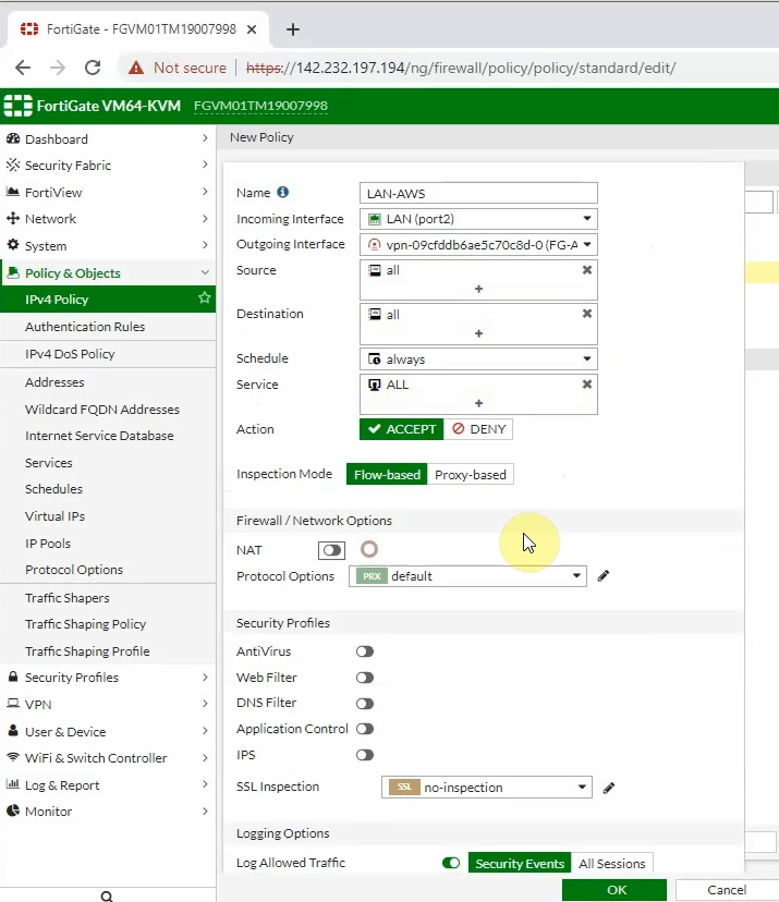
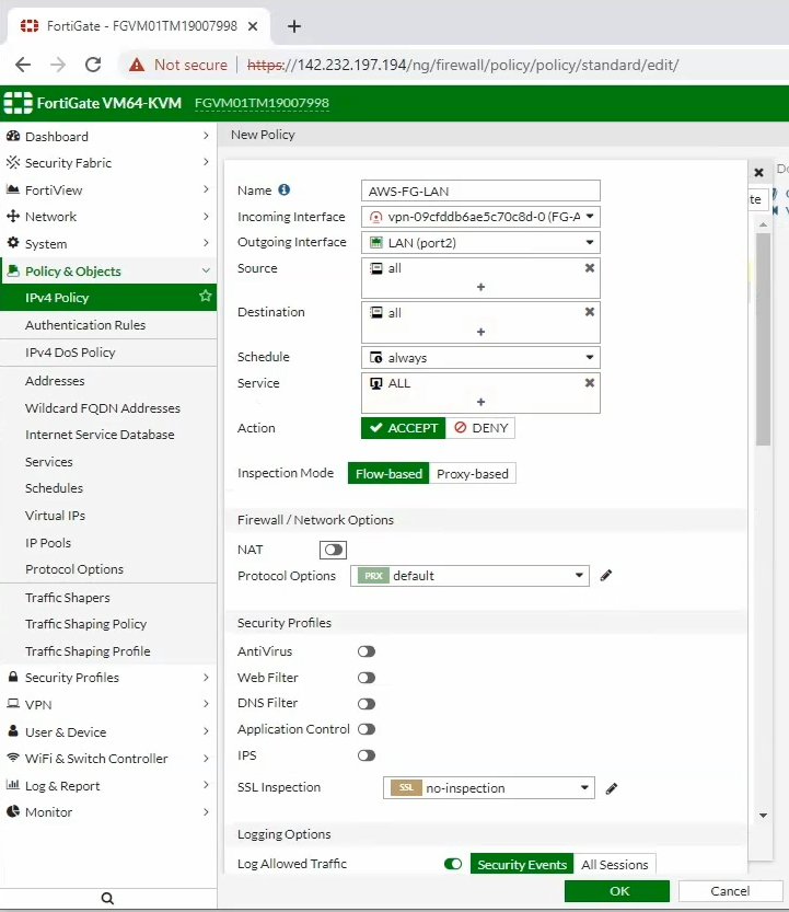
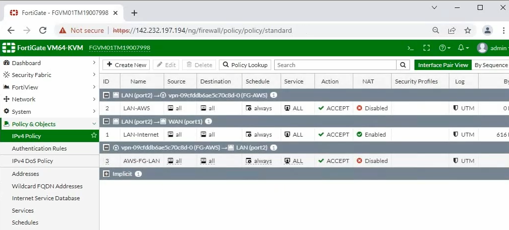
Configure access rules to allow FortiGate LAN subnets to communicate with AWS LAN subnets.
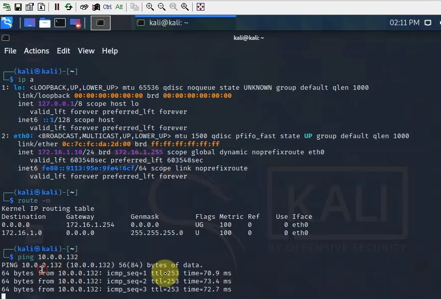
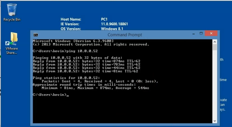
Pings from Kali machine to the Linux VM instance on AWS.
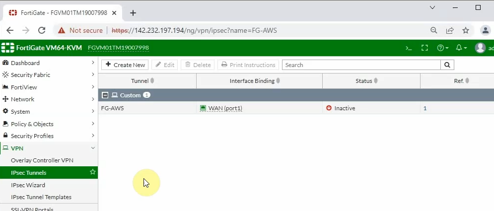
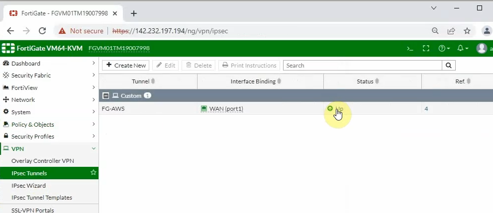
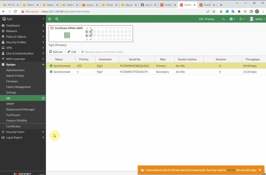
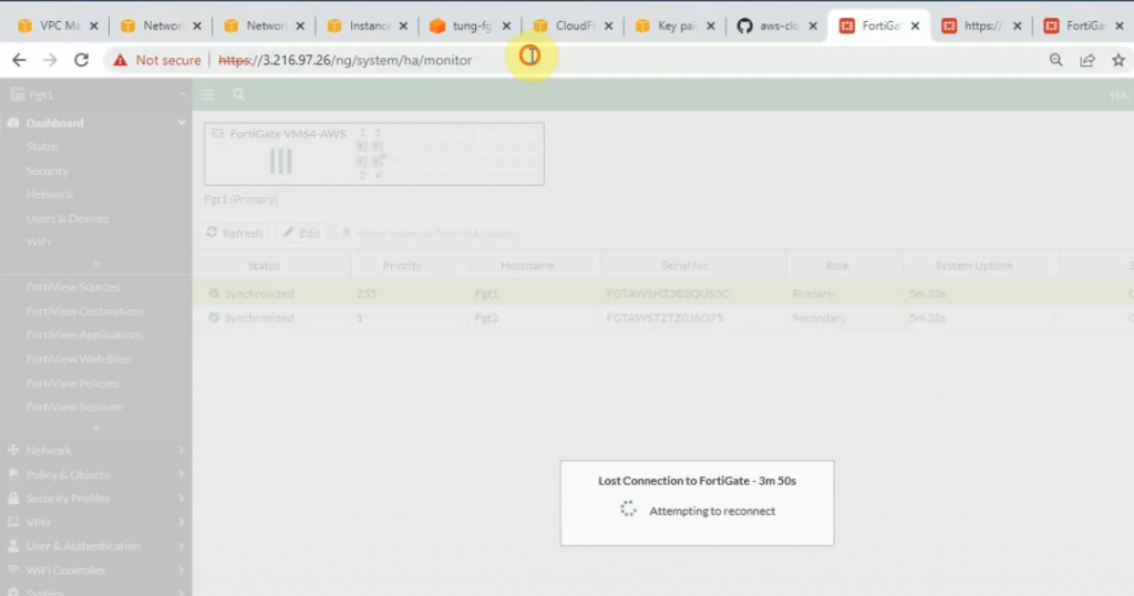
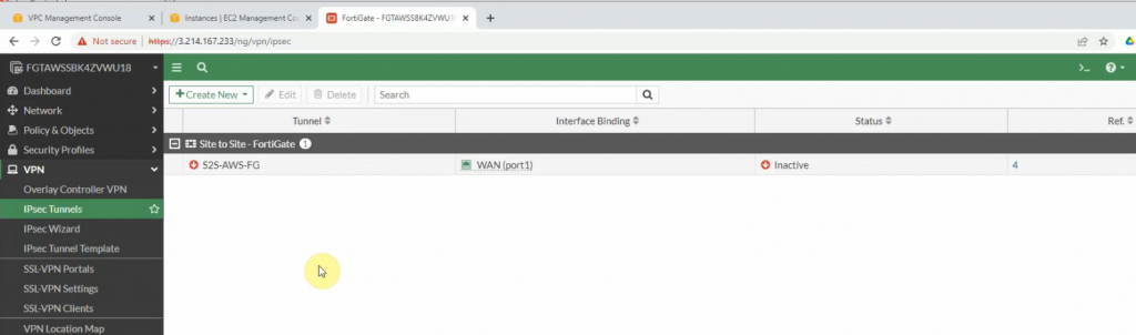
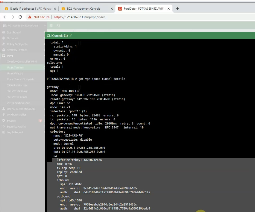
The IPSEC tunnel in FortiGate is up.
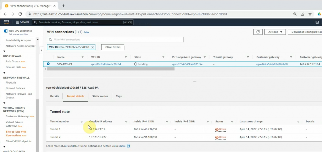
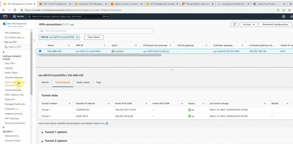
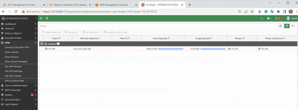
Back to AWS, the VPN tunnel is up.
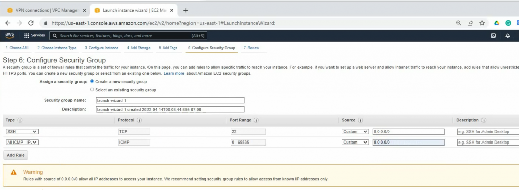
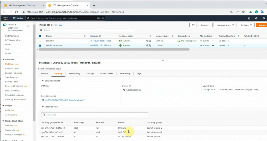
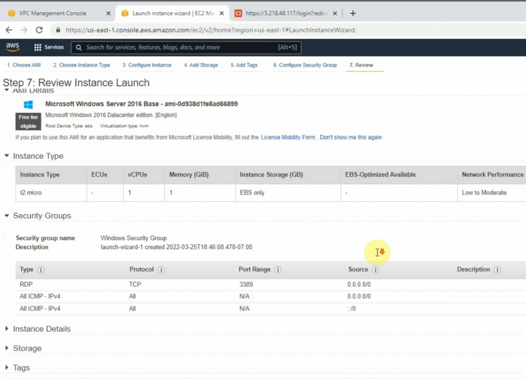
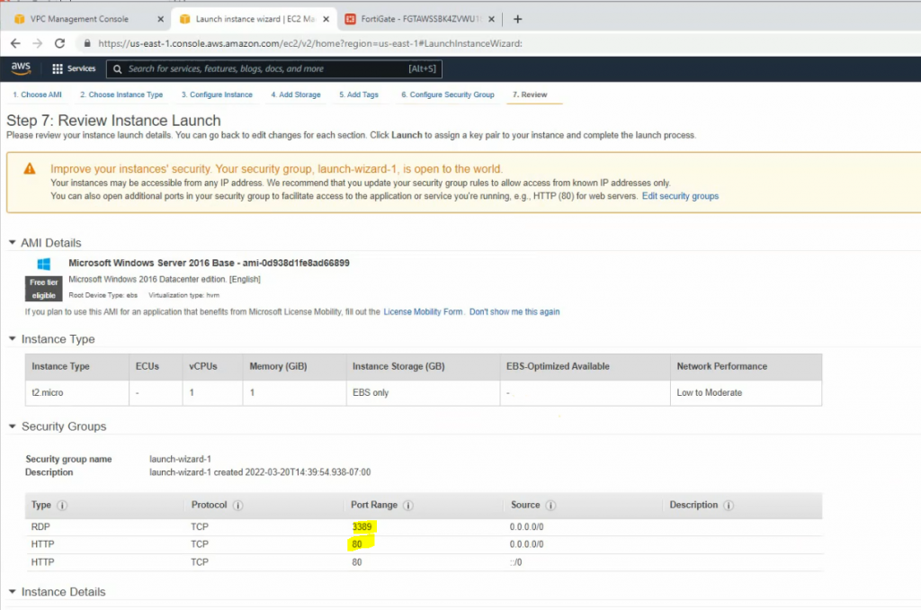
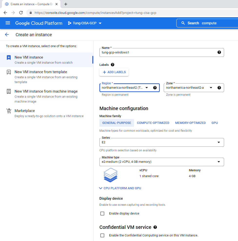
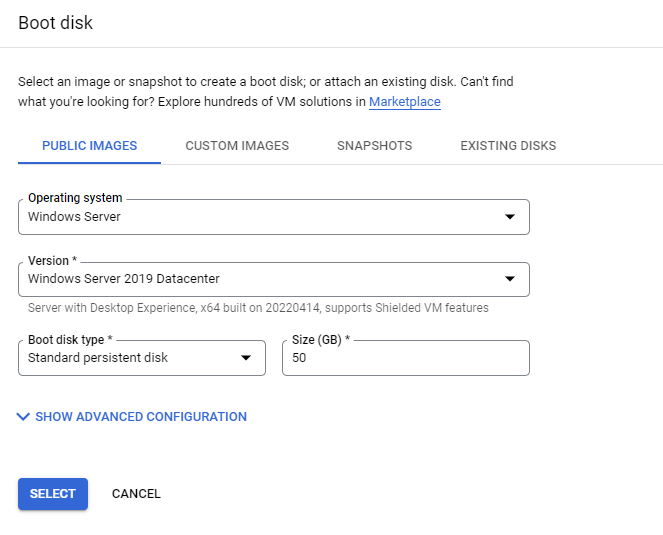
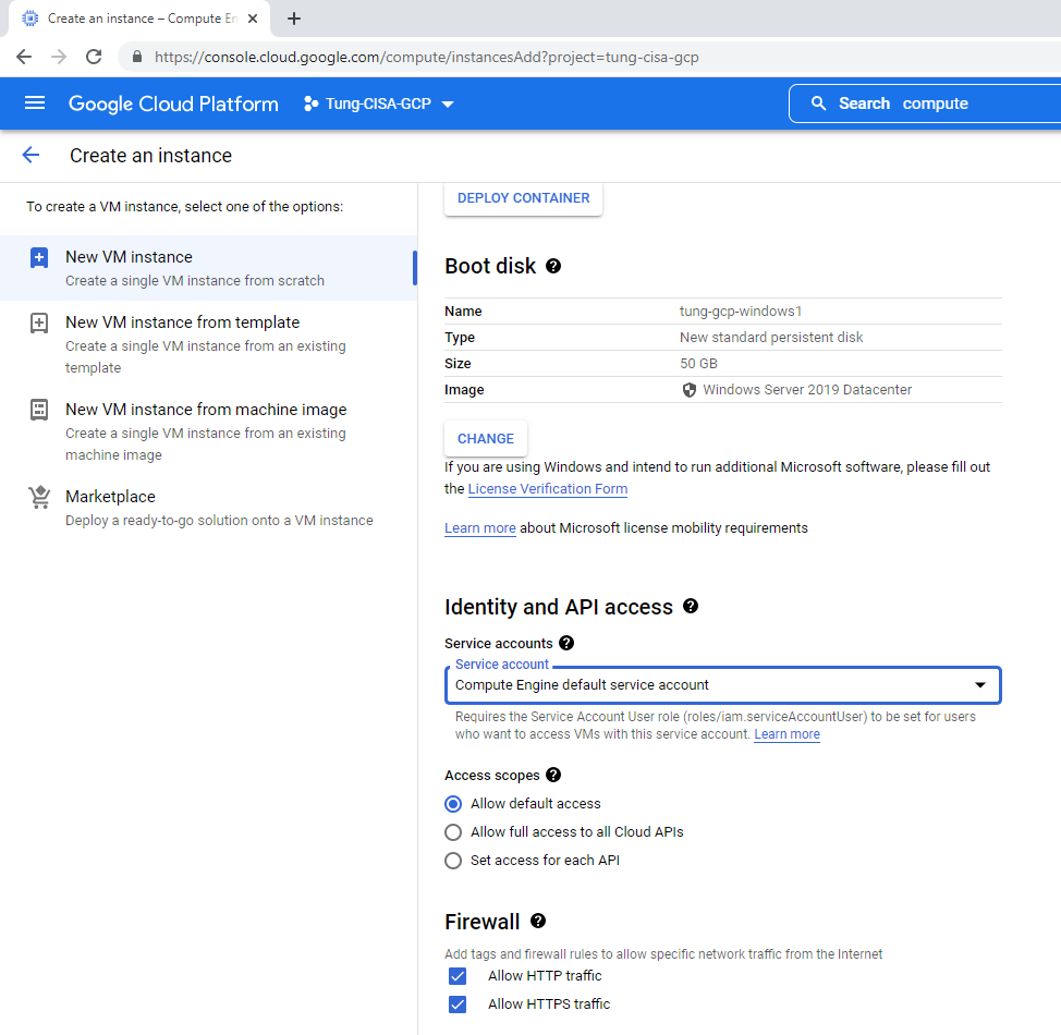
Launches a new Windows 2016 VM instance to install Splunk.
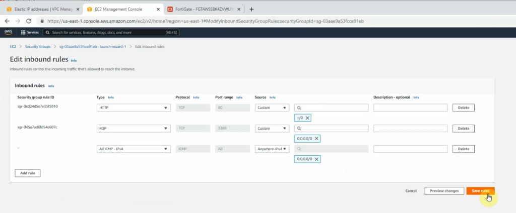
On Security Group, add a couple of rules to allow ICMP and all traffic on FortiGate LAN subnets to access this instance.
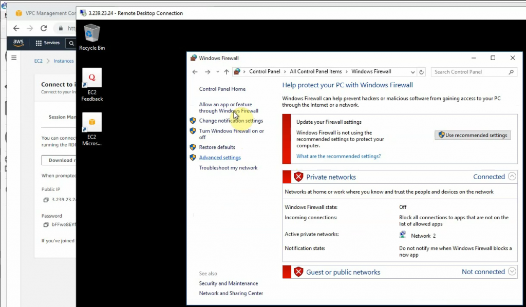
RDP to Windows instance and disable Firewall to send logs from FortiGate.
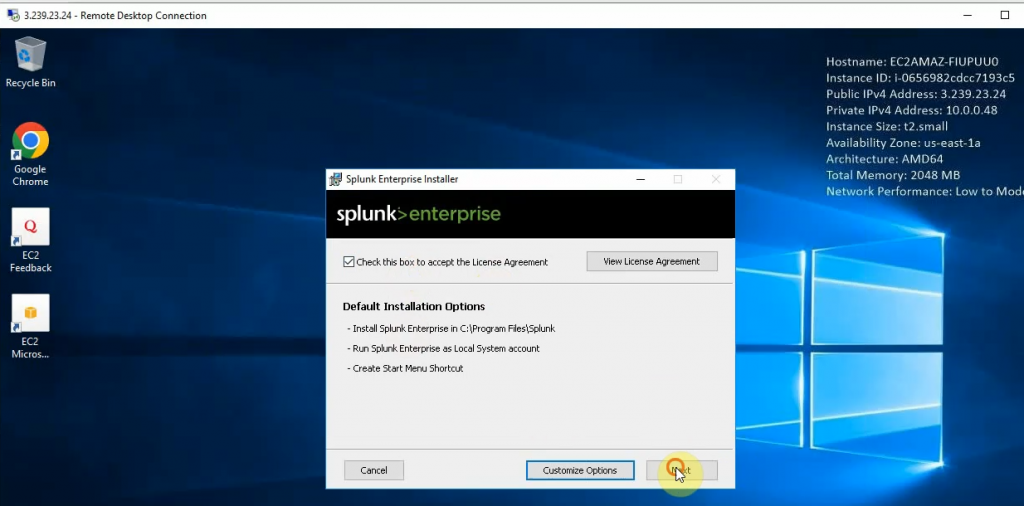
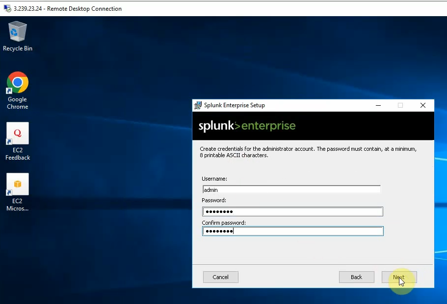
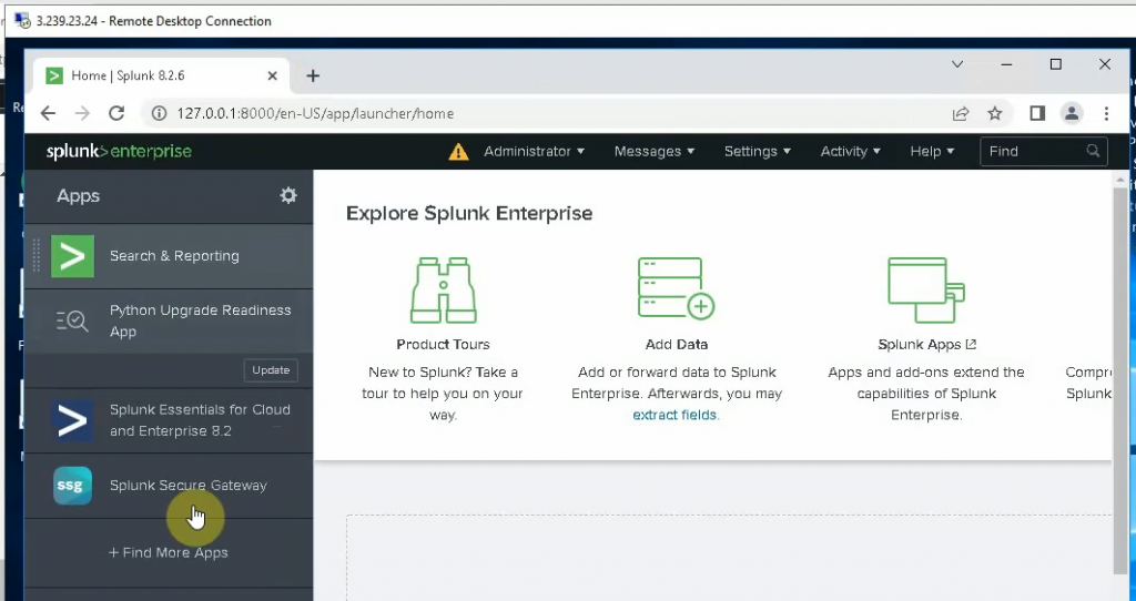
Download Splunk Enterprise for Windows and install it into this instance.
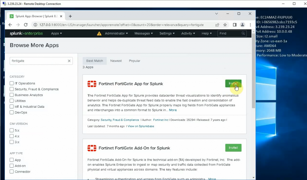
Install FortiGate App for Splunk and Fortinet FortiGate Add on Splunk.
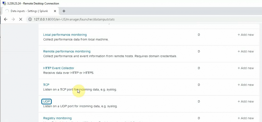
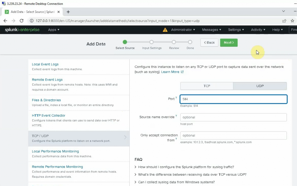
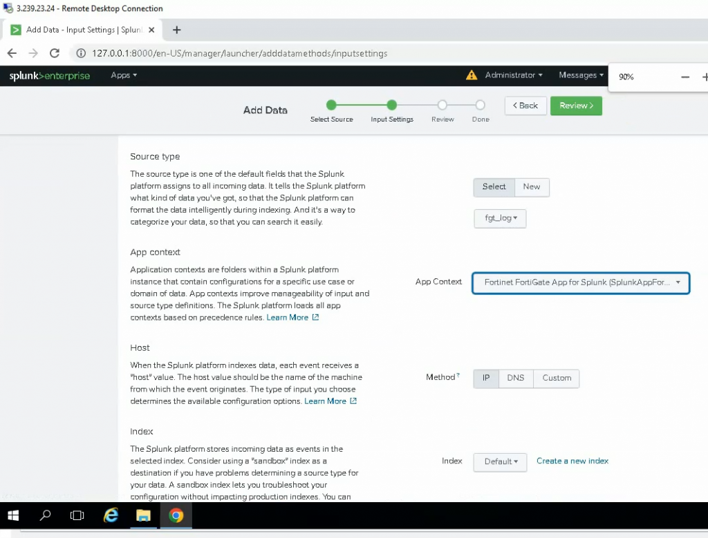
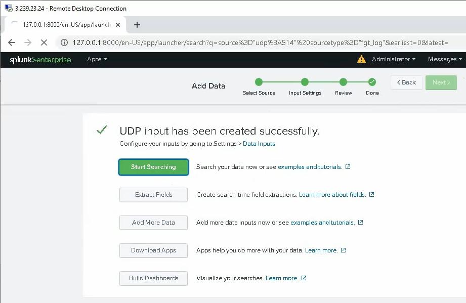
Click on the Settings tab and configure Splunk to get FortiGate logs. Select new Local UDP.
Enter 514 on the port setting. Be default, FortiGate is using UDP port 514 to send log to Syslog.
Select: fgt_log
App Context: Fortinet FortiGate App for Splunk
Method: IP
Index: Default
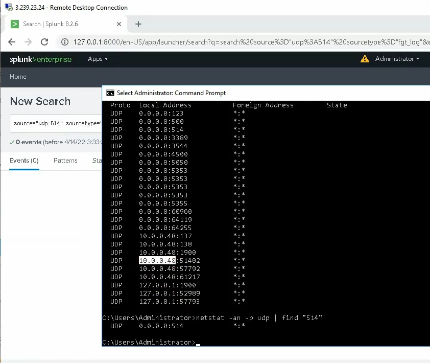
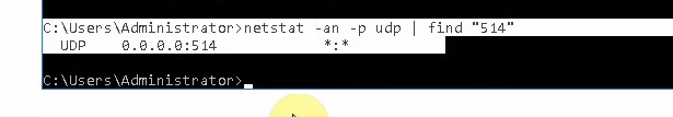
Check the UDP 514 port is running in the instance.
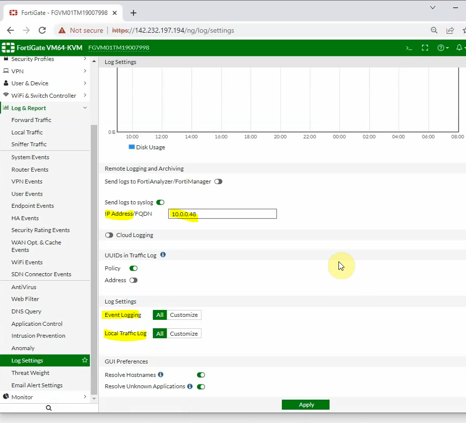
Back to FortiGate, configure Fortigate to send logs to Splunk on AWS. Enter the IP address of Splunk on the IP Address setting, and click choose All for “Event Logging” and “Local Logging”. Then, click Apply.
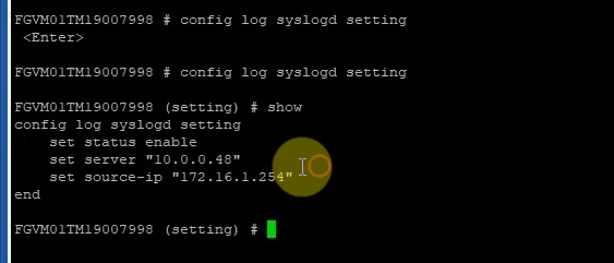
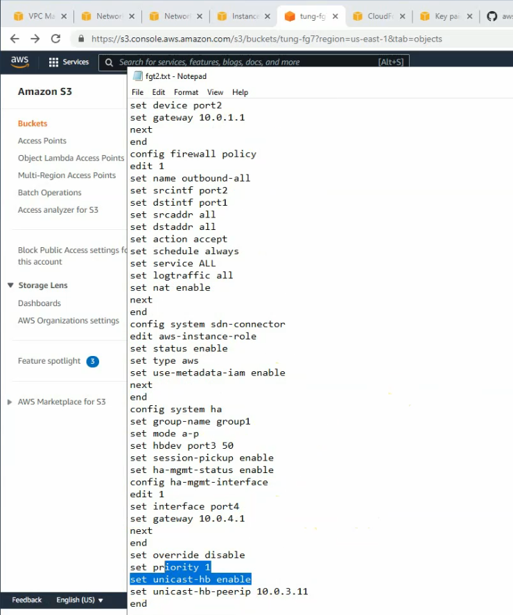
Log out of FortiGate and log back in to generate logs. If we may not see FortiGate logs on Splunk, we need to type the commands below to change the source-ip address to send log from using the “management interface” to using the LAN interface “172.16.1.254”
config log syslogd setting
    set status enable
    set mode udp
    set port 514
    set server "10.0.0.48"
    set source-ip "172.16.1.254"
end
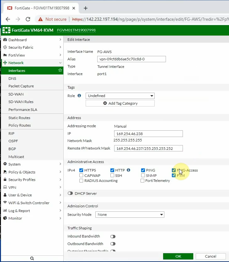
Also, enable PING Access, HTTP, and HTTPS on tunnel 1 interface of FortiGate.
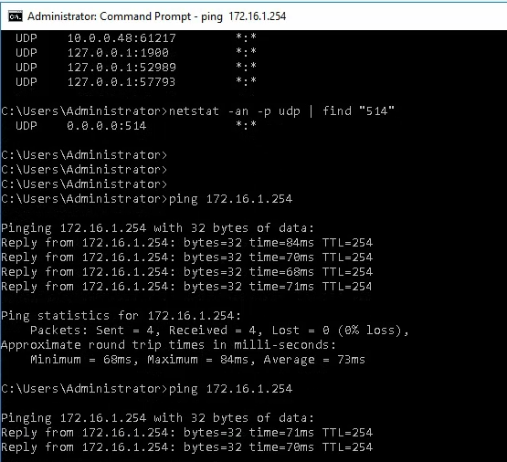
Splunk is able to ping the FortiGate LAN interface.
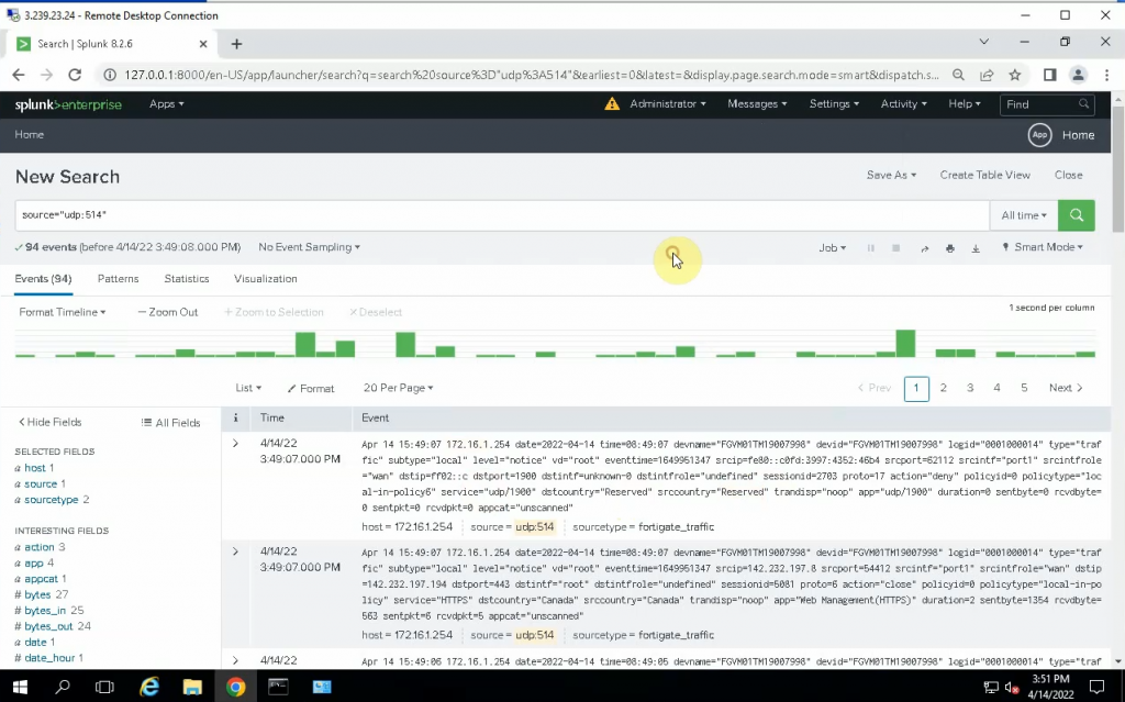
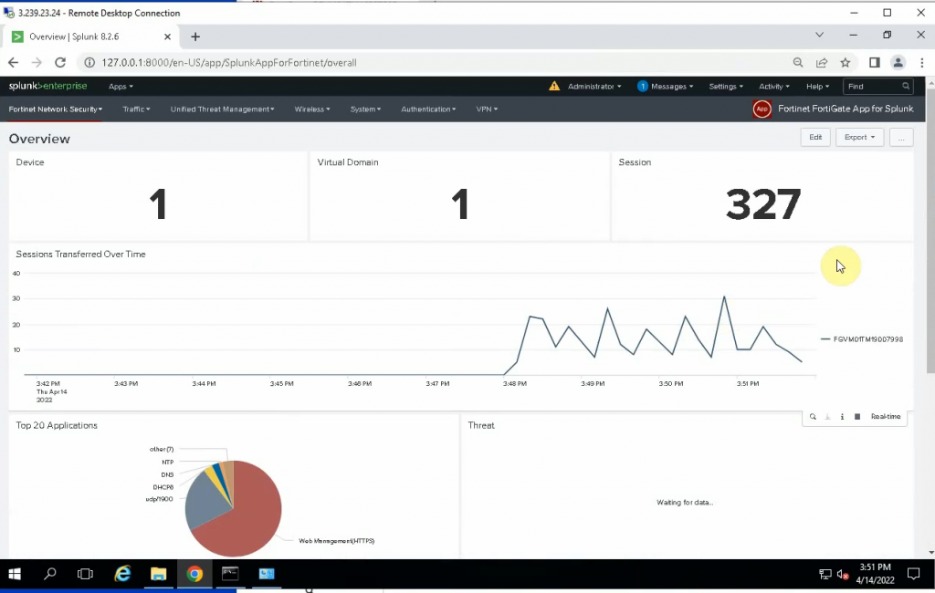
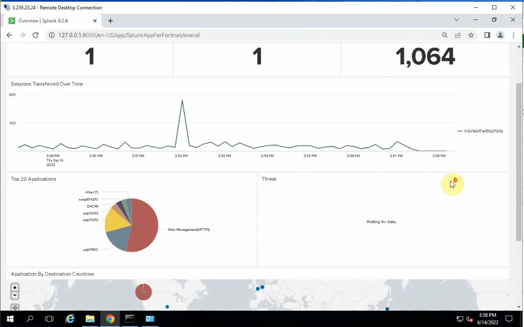
Back to the Splunk instance, now we are able to see logs from FortiGate.
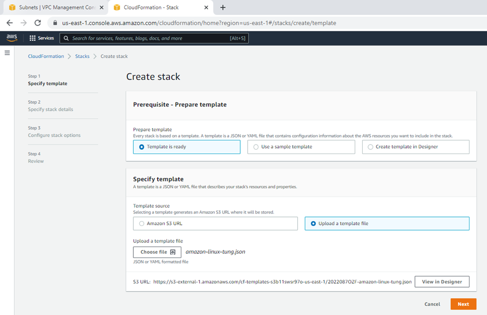
In this lab, I will explain how to use Docker compose to build your customized Docker image.
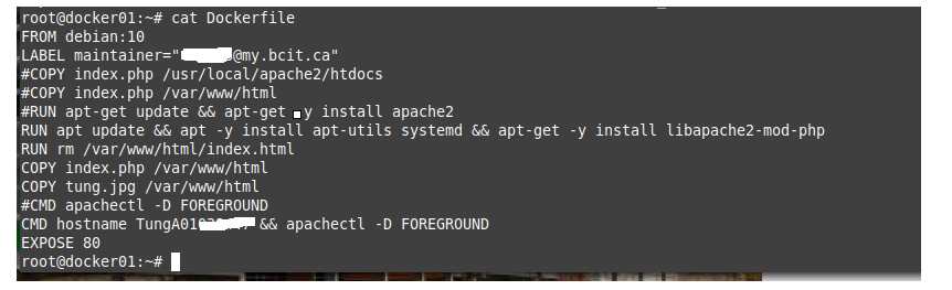
+ Create your sample docker file.
This tells Docker to: Build an image starting with the Debian 10 image. Label the container with your email address. Install Apache web service and PHP module. Remove the default index.html on the Apache web server document root directory. Copy a new index.php file and your customized image to the Apache document root directory on the docker container. Run the command hostname and apachectl -DFOREGROUND runs in the foreground. Image to describe that the container is listening on port 80.
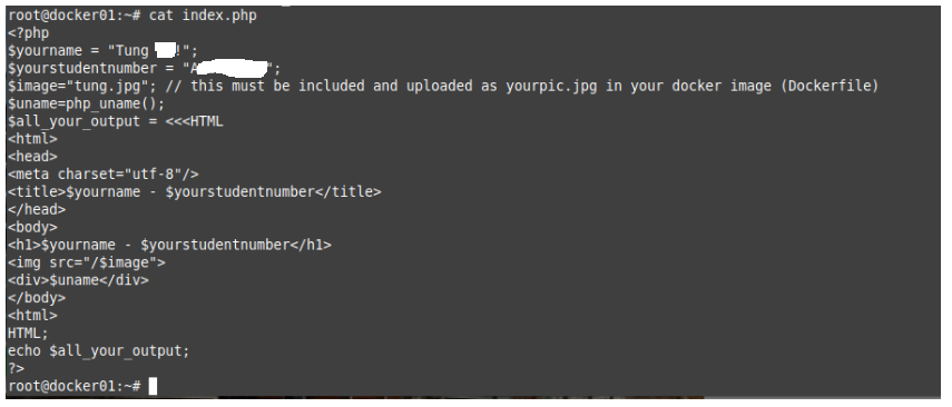
+ Create an index.php file with your customized information.
root@docker01:~# cat index.php
<?php
$yourname = "Tung Blog!";
$yourstudentnumber = "A123456789";
$image="tung.jpg"; // this must be included and uploaded as yourpic.jpg in your docker image (Dockerfile)
$uname=php_uname();
$all_your_output = <<<HTML
<html>
<head>
<meta charset="utf-8"/>
<title>$yourname - $yourstudentnumber</title>
</head>
<body>
<h1>$yourname - $yourstudentnumber</h1>
<img src="/$image">
<div>$uname</div>
</body>
<html>
HTML;
echo $all_your_output;
?>
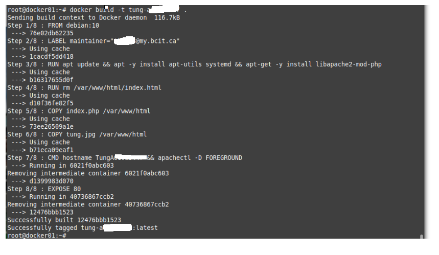
+ Build your app with Docker Compose.
docker build -t tung-a01234567 .
+ Run your app with Docker compose.
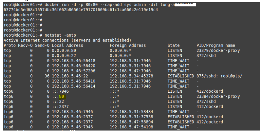
docker run -d -p 80:80 --cap-add sys_admin -dit tung-a01234567
---
-- -d starts docker in daemon mode, in the foreground.
-- -d p 80:80 listening the port 80 on docker container
-- -cap-add sys_admin: basically root access to the host.
-- -dit: it is used for getting access to terminal inside a docker container. In this example is tung-a01234567.
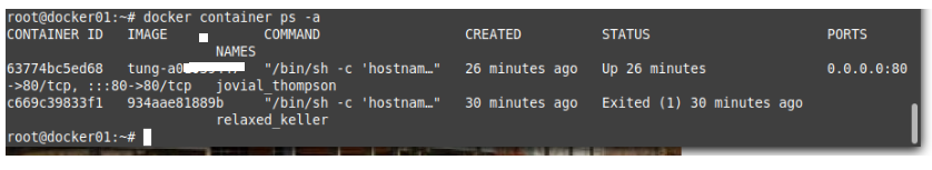
Check your application is running on a Docker container.
docker container ps -a
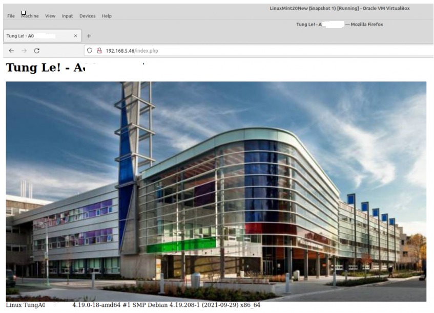
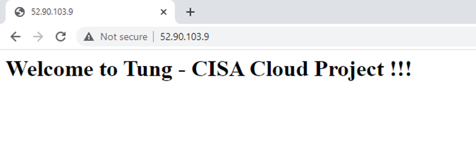
Connect to the Apache website with PHP module on the docker container.
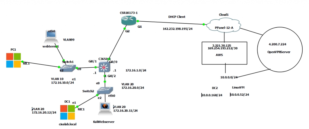
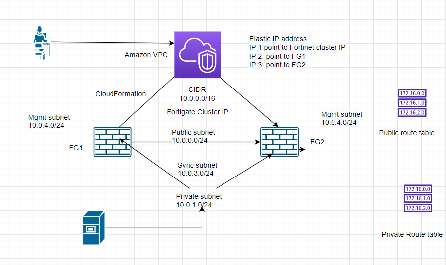
This is a diagram that is used to deploy this lab.
Create a new VPC with CIDR is 10.0.0.0/16. Then, create a new private subnet on AWS is 10.0.0.0/24.
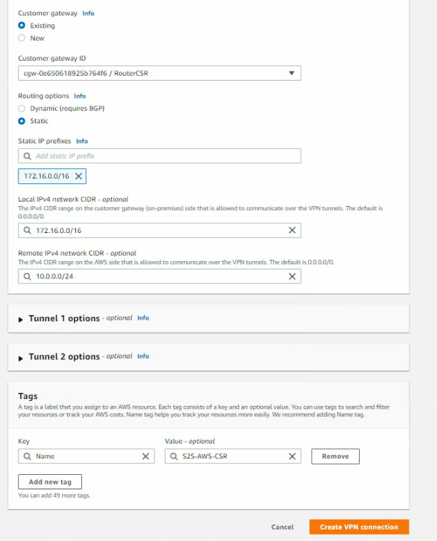
Next, create a Customer gateway on AWS.
Create a virtual private gateway and attach this to your VPC.
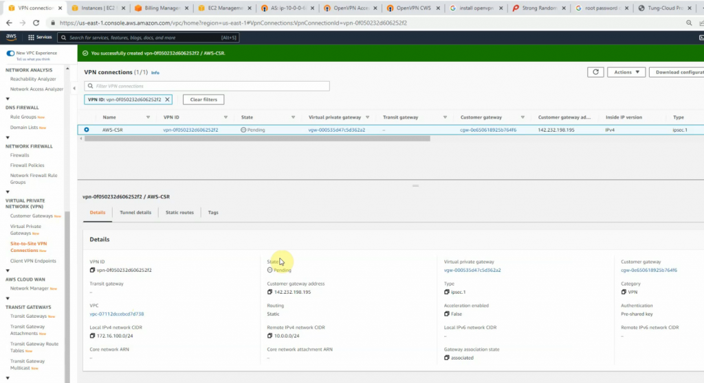
Create a site-to-site between AWS and Router CSR.
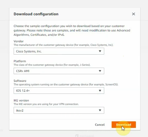
Click download configuration to configure on Cisco CSR.
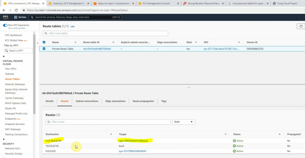
Add another route to Cisco CSR LAN subnets on AWS Private route table.
Configure CoreSW.
conf t
hostname CoreSW
ip routing
ip dhcp excluded-address 172.16.10.1 172.16.10.10
!
ip dhcp pool VLAN10
 network 172.16.10.0 255.255.255.0
 default-router 172.16.10.1
 dns-server 172.16.20.12

interface GigabitEthernet0/0
 no switchport
 ip address 172.16.1.1 255.255.255.0
!
interface GigabitEthernet0/1
 switchport trunk allowed vlan 10,20,99
 switchport trunk encapsulation dot1q
 switchport trunk native vlan 99
 switchport mode trunk
 negotiation auto
!
interface GigabitEthernet0/2
 switchport trunk allowed vlan 10,20,99
 switchport trunk encapsulation dot1q
 switchport trunk native vlan 99
 switchport mode trunk

interface Vlan10
 ip address 172.16.10.1 255.255.255.0
!
interface Vlan20
 ip address 172.16.20.1 255.255.255.0
!
router ospf 1
 router-id 1.1.1.1
 network 172.16.0.0 0.0.255.255 area 0
!
ip route 0.0.0.0 0.0.0.0 172.16.1.254
--
Configure VLAN
CoreSW(config)#vlan 10
CoreSW(config-vlan)#name PCs
CoreSW(config-vlan)#vlan 20
CoreSW(config-vlan)#name Servers
CoreSW(config-vlan)#vlan 99
CoreSW(config-vlan)#name Native
CoreSW(config-vlan)#do sh vlan bri

VLAN Name                             Status    Ports
---- -------------------------------- --------- -------------------------------
1    default                          active    Gi0/3, Gi1/0, Gi1/1, Gi1/2
                                                Gi1/3, Gi2/0, Gi2/1, Gi2/2
                                                Gi2/3, Gi3/0, Gi3/1, Gi3/2
                                                Gi3/3
10   PCs                              active
20   Servers                          active
99   Native                           active
Configure Cisco CSR.
interface GigabitEthernet1
 ip address dhcp
 ip nat outside
 negotiation auto
 no mop enabled
 no mop sysid
!
interface GigabitEthernet2
 ip address 172.16.1.254 255.255.255.0
 ip nat inside
 negotiation auto
 no mop enabled
 no mop sysid
router ospf 1
 router-id 3.3.3.3
 network 172.16.0.0 0.0.255.255 area 0
!
ip nat inside source list 1 interface GigabitEthernet1 overload
ip route 0.0.0.0 0.0.0.0 142.232.198.254
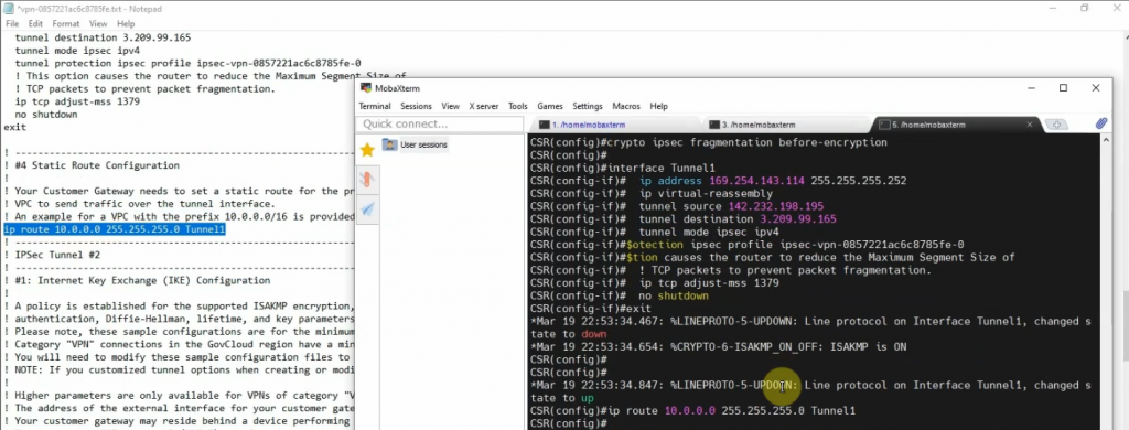
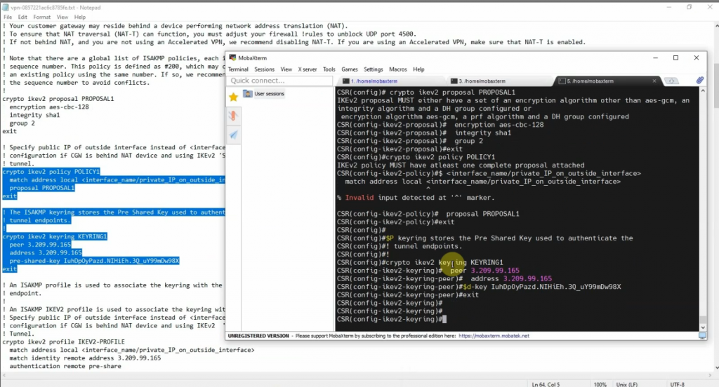
Next, opens the file that you have downloaded on AWS, then copy and paste its configuration to Cisco CSR to create both IPSEC VPN site-to-site IKEv2 tunnels on the Router.
Cisco CSR configuration
-------
crypto ikev2 proposal PROPOSAL1
encryption aes-cbc-128
integrity sha1
group 2
!
crypto ikev2 policy POLICY1
match address local 142.232.198.195
proposal PROPOSAL1
!
crypto ikev2 keyring KEYRING1
peer 3.209.99.165
address 3.209.99.165
pre-shared-key IuhDpOyPazd.NIHiEh.3Q_uY99mDw98X
!
peer 54.83.195.0
address 54.83.195.0 255.255.255.0
pre-shared-key tlDEo5uQkac9zzMt3s.kgU6ARGma5Cq8
!
!crypto ikev2 profile IKEV2-PROFILE
match address local 142.232.198.195
match identity remote address 3.209.99.165 255.255.255.255
match identity remote address 54.83.195.0 255.255.255.0
authentication remote pre-share
authentication local pre-share
keyring local KEYRING1
lifetime 28800
dpd 10 10 on-demand
crypto isakmp keepalive 10 10
!
crypto ipsec security-association replay window-size 128
!
crypto ipsec transform-set ipsec-prop-vpn-0857221ac6c8785fe-0 esp-aes esp-sha-hmac
mode tunnel
crypto ipsec transform-set ipsec-prop-vpn-0857221ac6c8785fe-1 esp-aes esp-sha-hmac
mode tunnel
crypto ipsec df-bit clear
!
crypto ipsec profile ipsec-vpn-0857221ac6c8785fe-0
set transform-set ipsec-prop-vpn-0857221ac6c8785fe-0
set pfs group2
set ikev2-profile IKEV2-PROFILE
!
crypto ipsec profile ipsec-vpn-0857221ac6c8785fe-1
set transform-set ipsec-prop-vpn-0857221ac6c8785fe-1
set pfs group2
set ikev2-profile IKEV2-PROFILE
interface Tunnel1
ip address 169.254.143.114 255.255.255.252
ip tcp adjust-mss 1379
tunnel source 142.232.198.195
tunnel mode ipsec ipv4
tunnel destination 3.209.99.165
tunnel protection ipsec profile ipsec-vpn-0857221ac6c8785fe-0
ip virtual-reassembly
!
interface Tunnel2
ip address 169.254.192.6 255.255.255.252
ip tcp adjust-mss 1379
tunnel source 142.232.198.195
tunnel mode ipsec ipv4
tunnel destination 54.83.195.0
tunnel protection ipsec profile ipsec-vpn-0857221ac6c8785fe-1
ip virtual-reassembly
!
interface GigabitEthernet1
ip address dhcp
ip nat outside
negotiation auto
no mop enabled
no mop sysid
!
interface GigabitEthernet2
ip address 172.16.1.254 255.255.255.0
ip nat inside
negotiation auto
no mop enabled
no mop sysid
router ospf 1
router-id 3.3.3.3
network 172.16.0.0 0.0.255.255 area 0
!
ip nat inside source list 1 interface GigabitEthernet1 overload
ip route 0.0.0.0 0.0.0.0 142.232.198.254
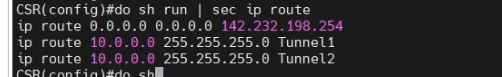
ip route 10.0.0.0 255.255.255.0 Tunnel1
ip route 10.0.0.0 255.255.255.0 Tunnel2
!
ip access-list standard 1
10 permit any
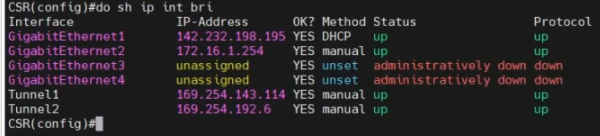
show CSR interfaces.
CSR# sh ip int brief
Interface              IP-Address      OK? Method Status                Protocol
GigabitEthernet1       142.232.198.195 YES DHCP   up                    up
GigabitEthernet2       172.16.1.254    YES manual up                    up
GigabitEthernet3       unassigned      YES unset  administratively down down
GigabitEthernet4       unassigned      YES unset  administratively down down
Tunnel1                169.254.143.114 YES manual up                    up
Tunnel2                169.254.192.6   YES manual up                    up
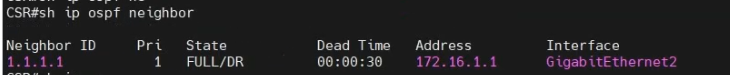
show ip ospf neighbor
show ip route
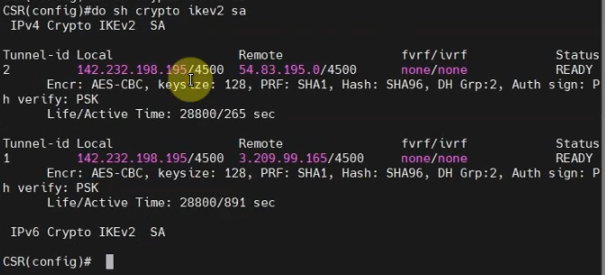
show crypt ikev2 sa
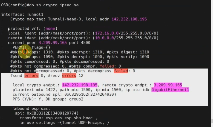
show crypto ipsec sa
show crypto ipsec sa
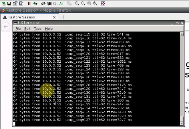
Pings Linux instance on AWS from a machine on CSR LAN subnet.
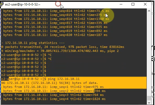
Pings a Windows machine on CSR LAN subnet from the Linux instance on AWS.
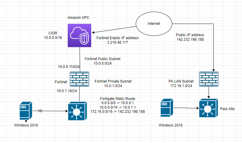
This is a diagram to show how to create a VPN site to site connection from PA on-prem and FG on AWS.
In this lab:
Create a VPC, subnets, Internet gateway, route tables.
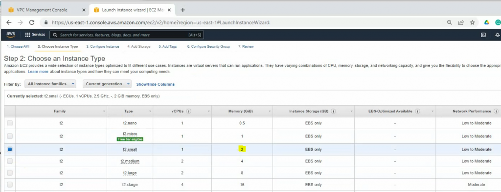
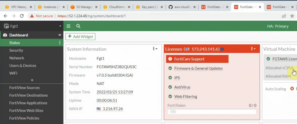
Create a FortiGate VM and Windows 2016 instance on AWS
Configure Palo Alto
Create VPN site to site between both sites PA and FortiGate
Allow Windows 2016 instance to access the Internet via FortiGate. Also, allow RDP to this machine via the Internet by using FortiGate.
Test ping traffic between both sites.
Allow a machine on the PA LAN subnet to access the Internet and the Windows 2016 instance on AWS.
Create a new SSLVPN portal on AWS and test to access the portal via SSLVPN.
+ Below are a couple of steps to deploy FortiGate on AWS.
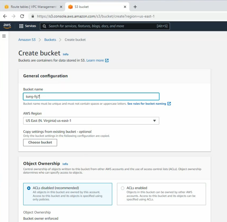
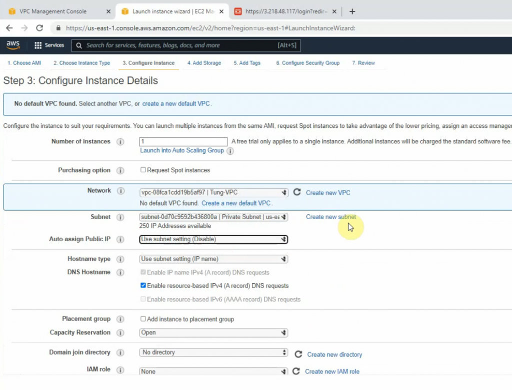
Create a new VPC.
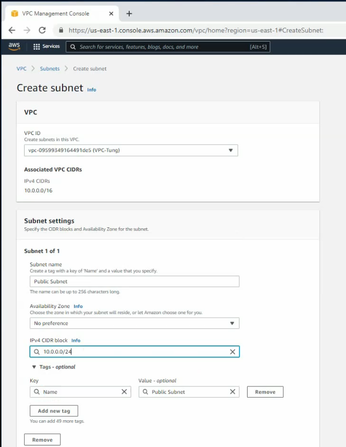
Create a public subnet.
Create a private subnet.
Create an Internet gateway.
Attach the gateway to your VPC.
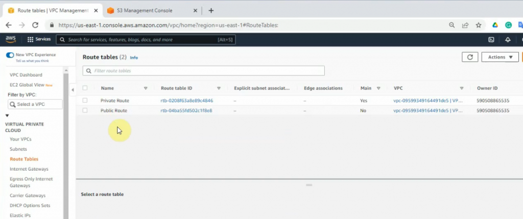
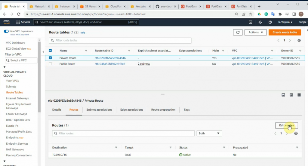
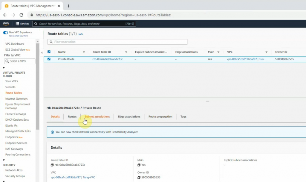
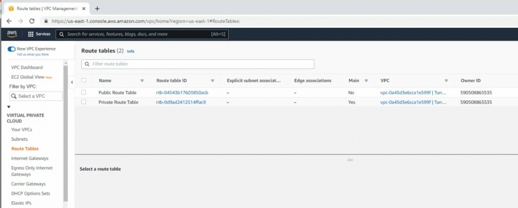
Edit Route table, change default Route table to Private Route.
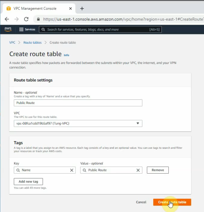
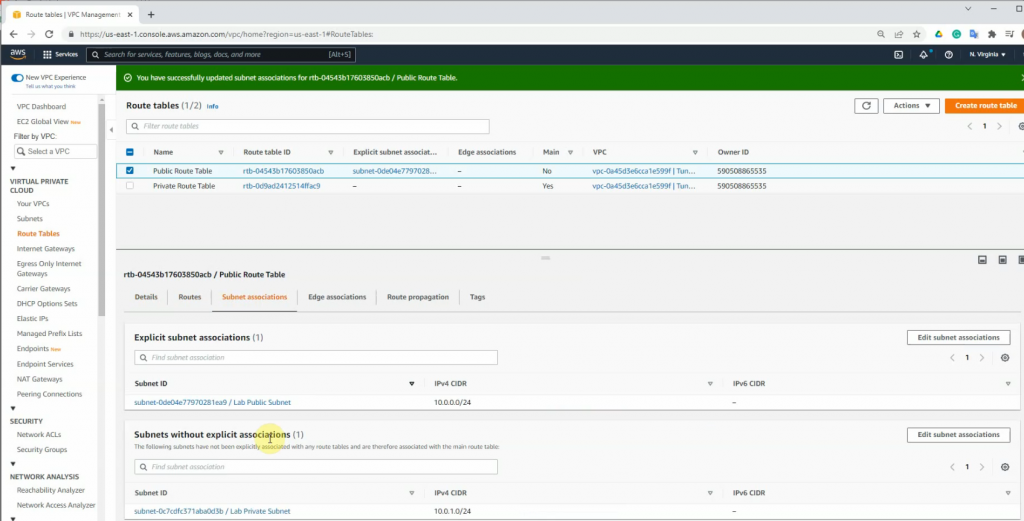
Create a Public Route Table.
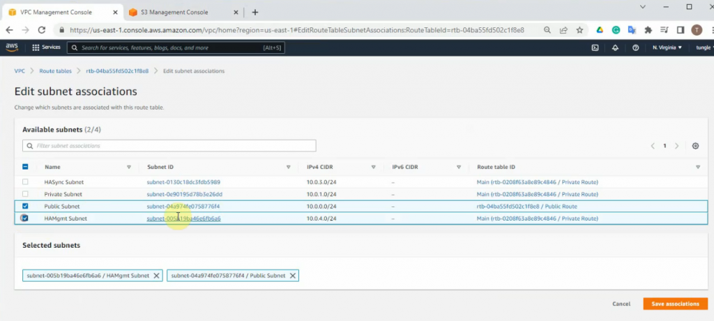
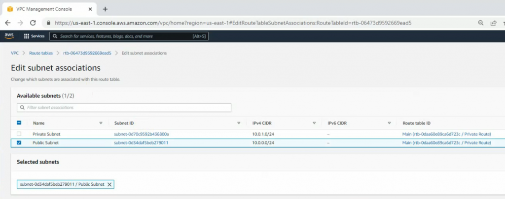
Link the Public Subnet to the Public Route.
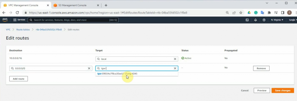
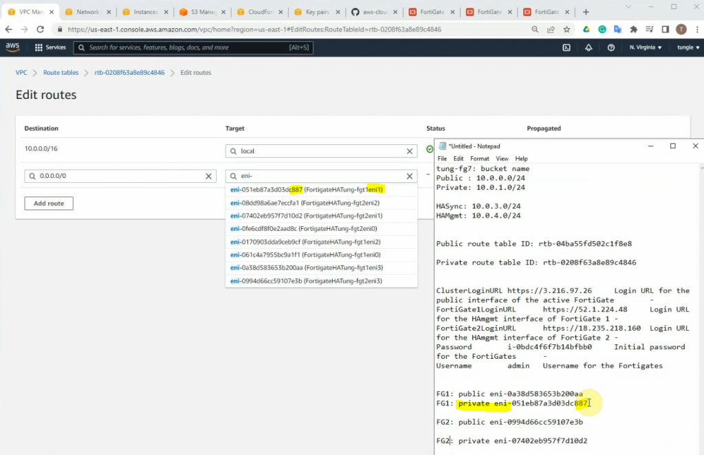
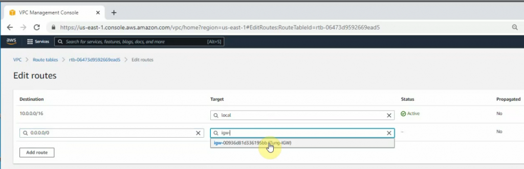
Add a new route 0.0.0.0/0 to your Internet gateway.
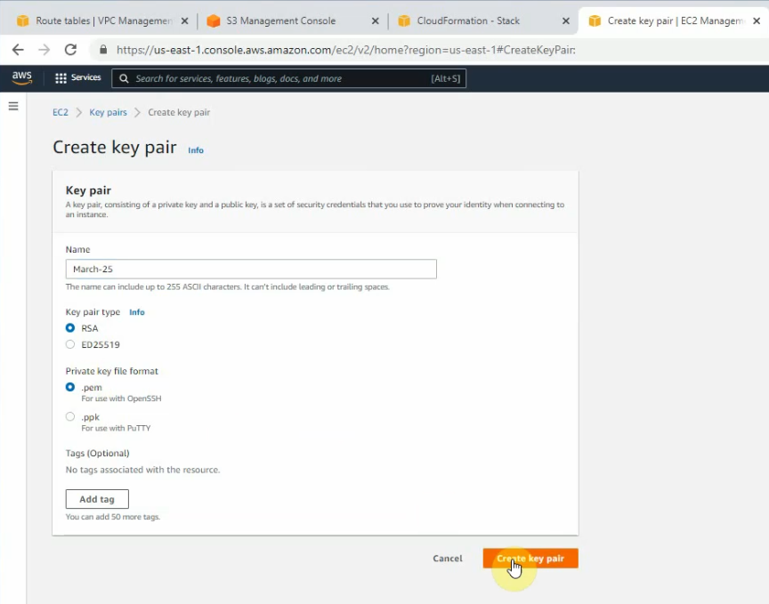
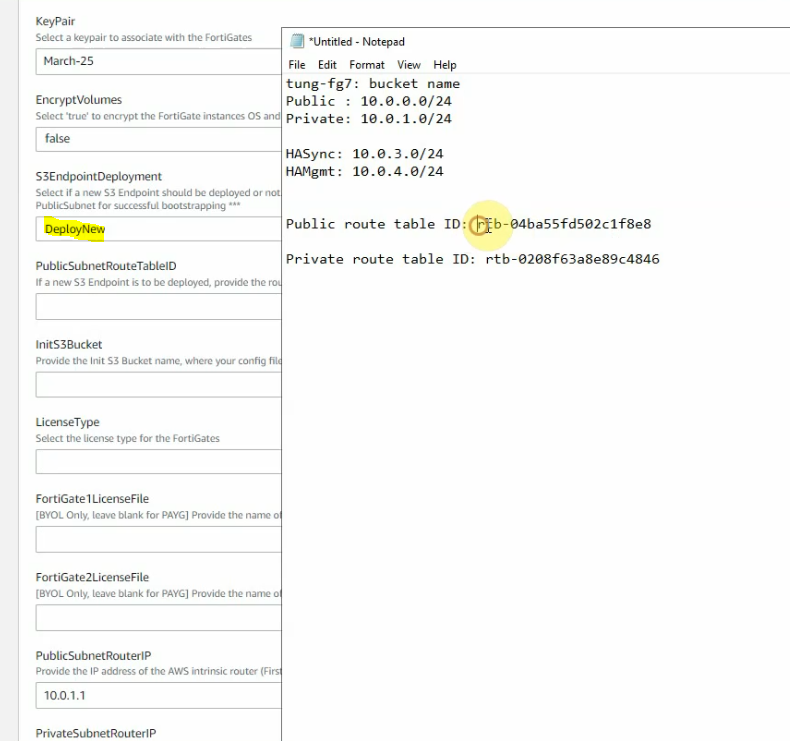
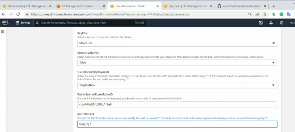
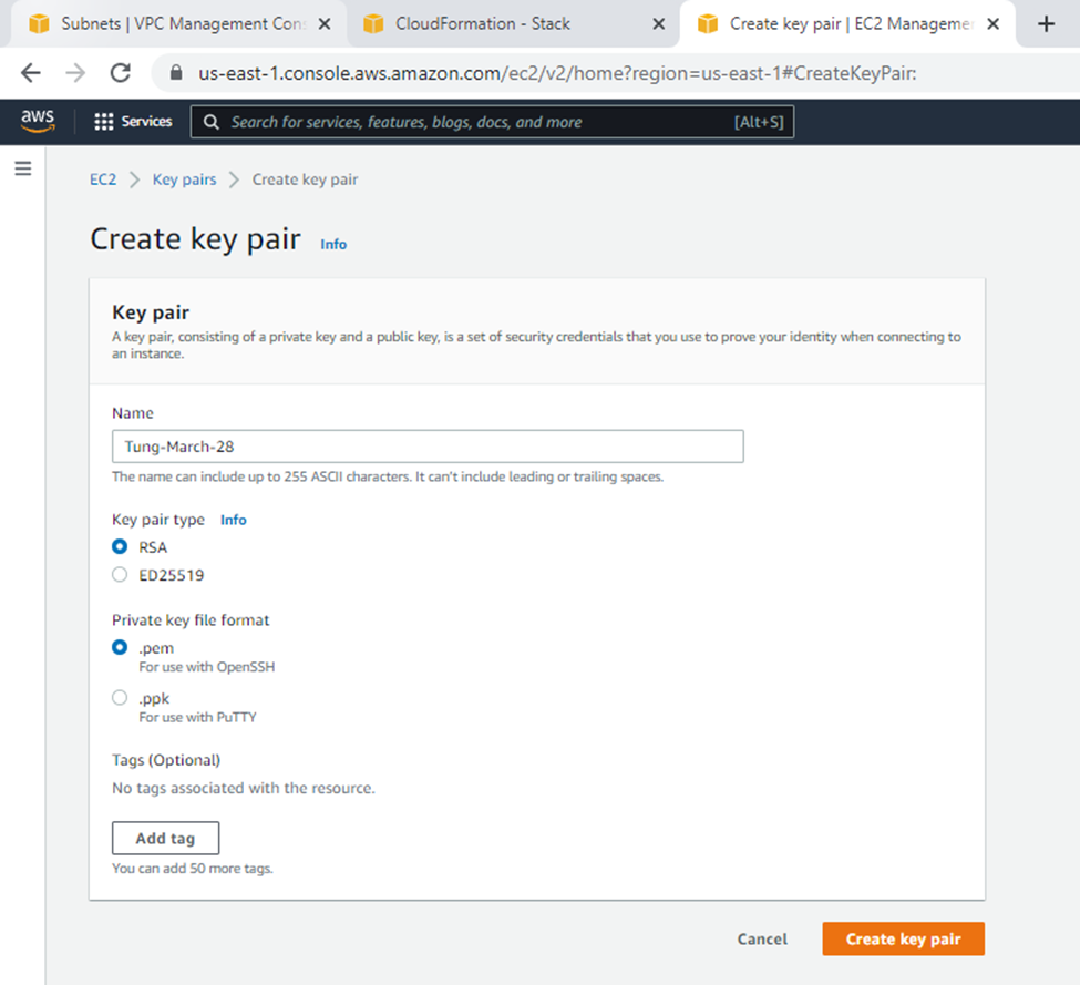
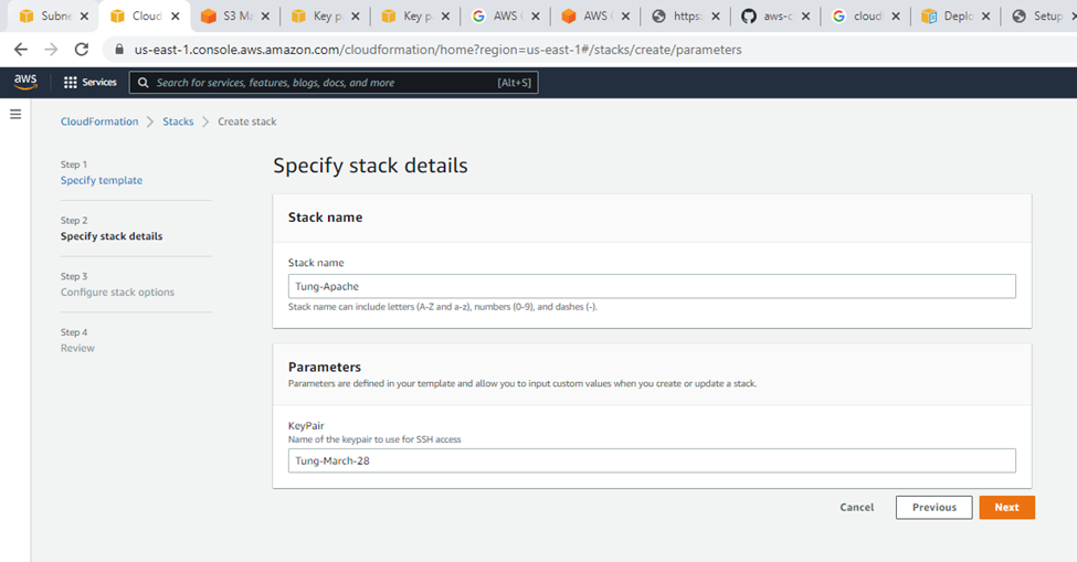
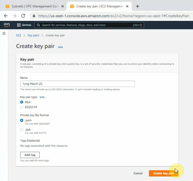
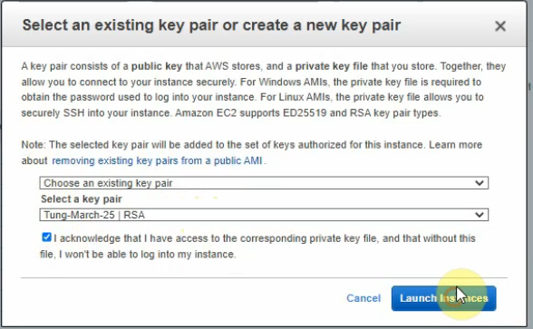
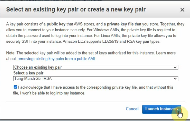
Create a new key pair.
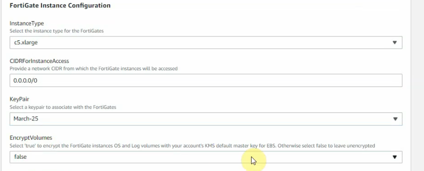
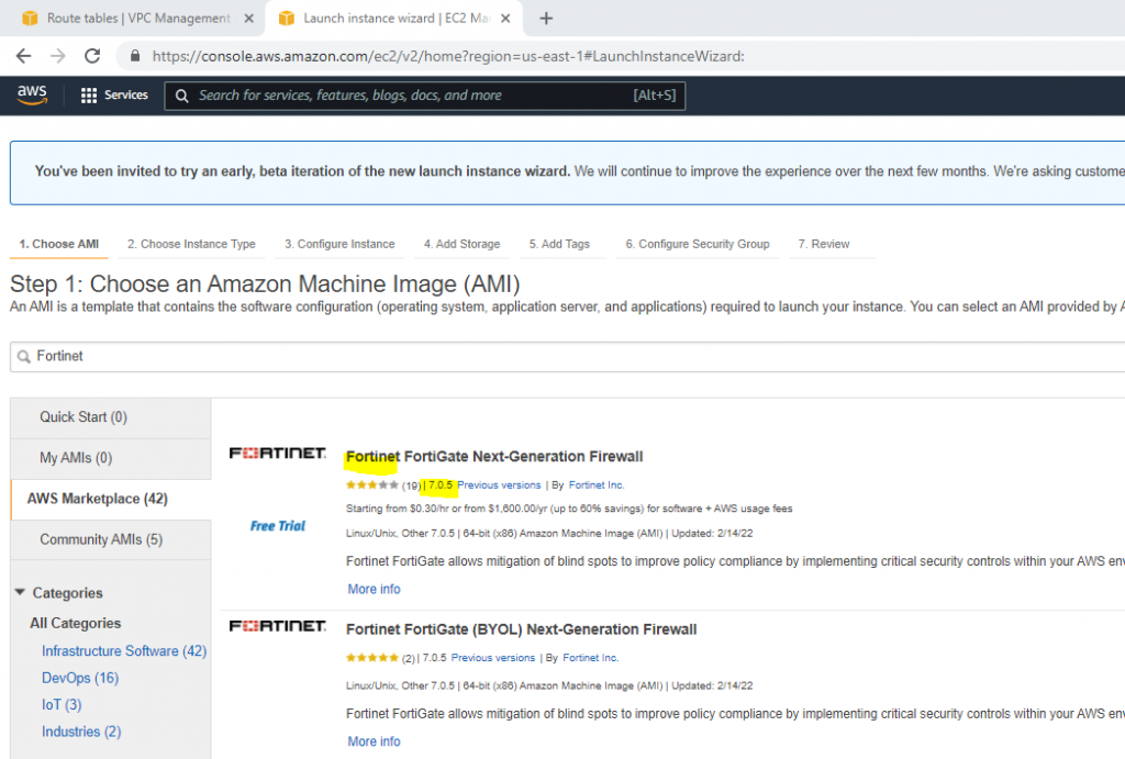
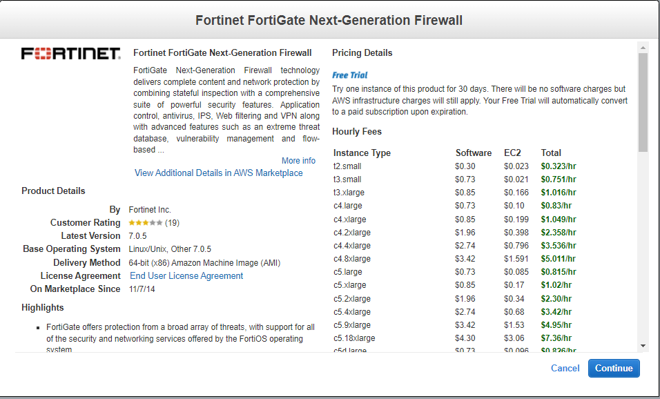
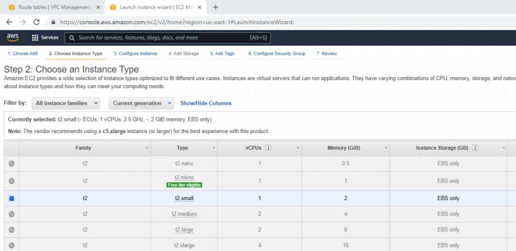
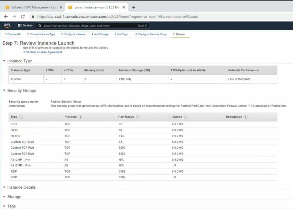
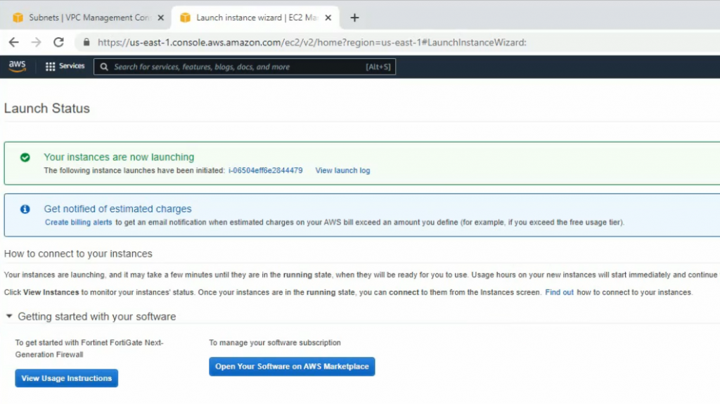
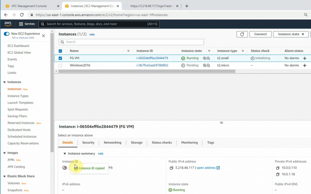
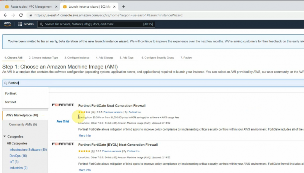
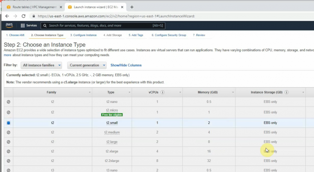
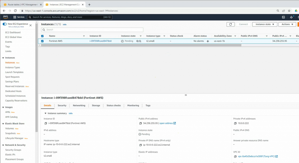
+ Go to EC2, and deploy Fortinet on AWS.
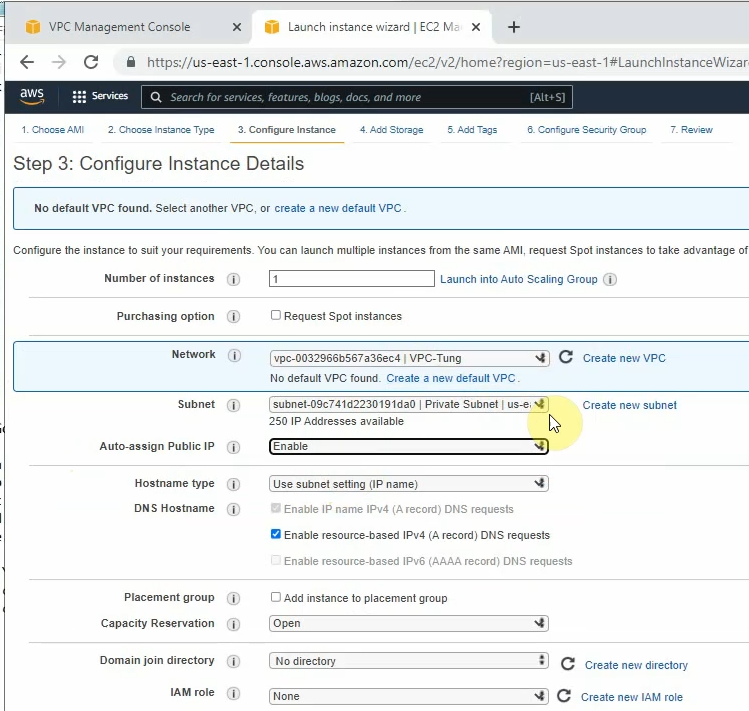
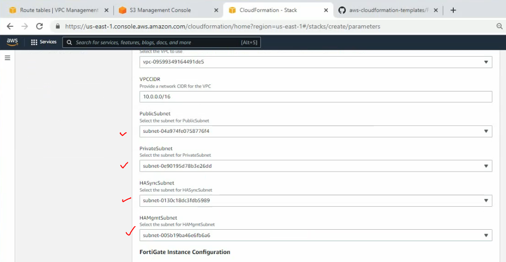
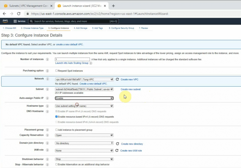
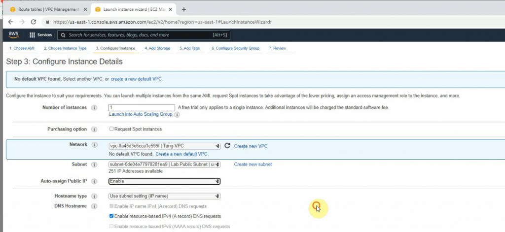
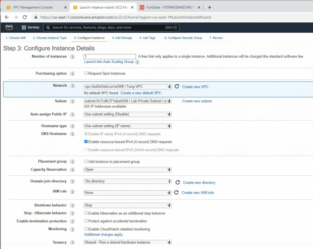
Select your VPC, the subnet belongs to Lab Public Subnet. Also, changing the Auto-assign Public IP is Enable.
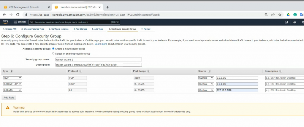
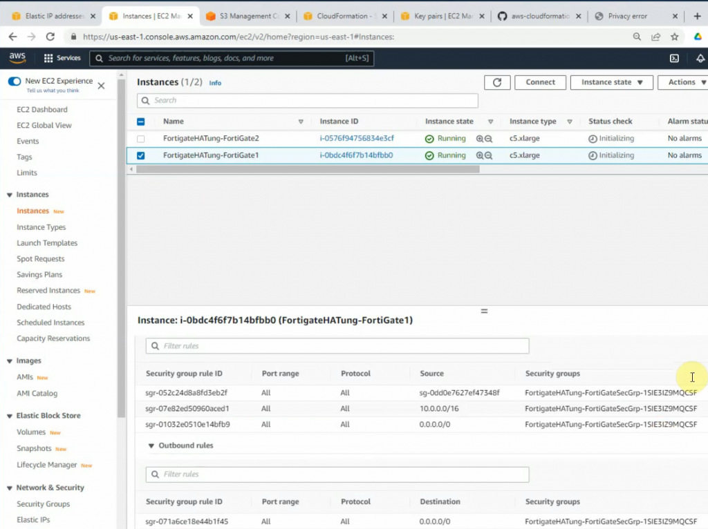
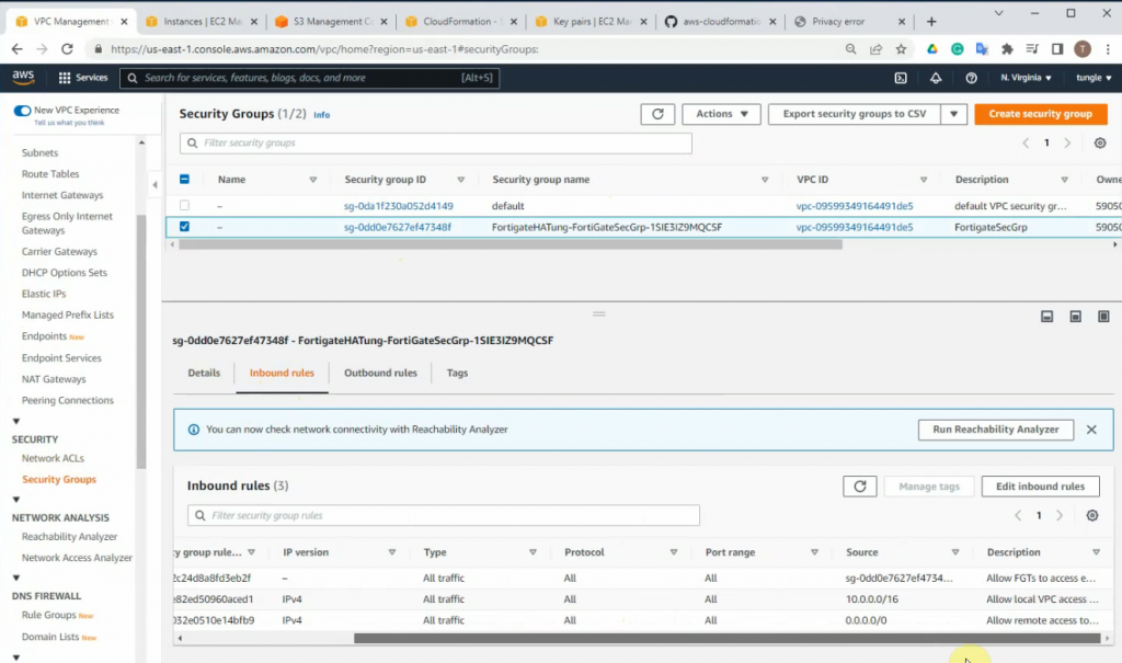
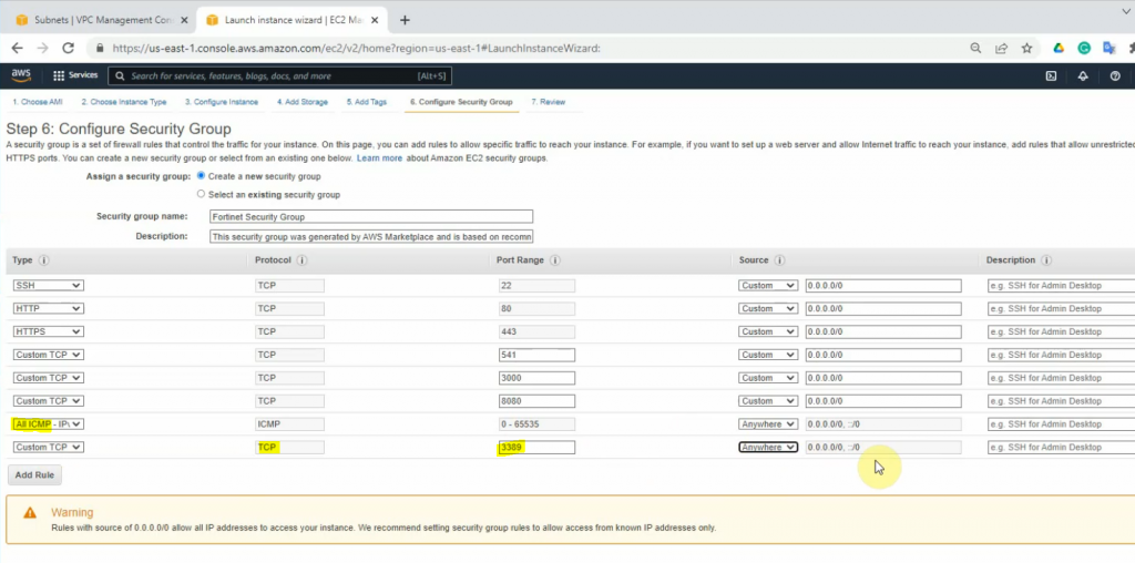
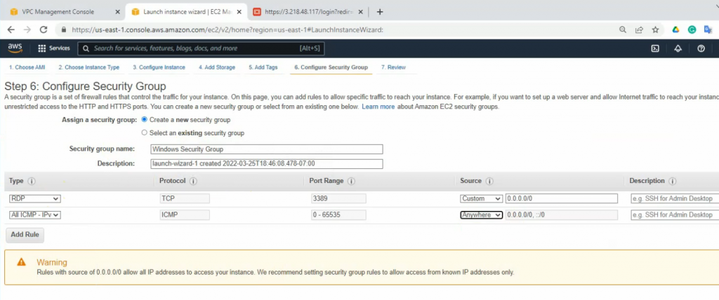
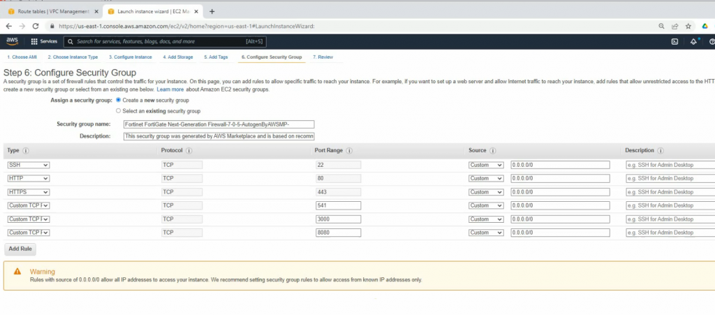
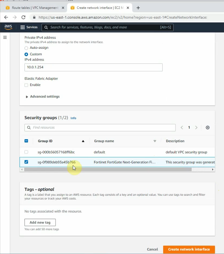
On the Security Group tab, add new two lines at the end of Security Group as a screenshot below. This allows to ping and RDP to the Windows 2016 machine on a private subnet later on.
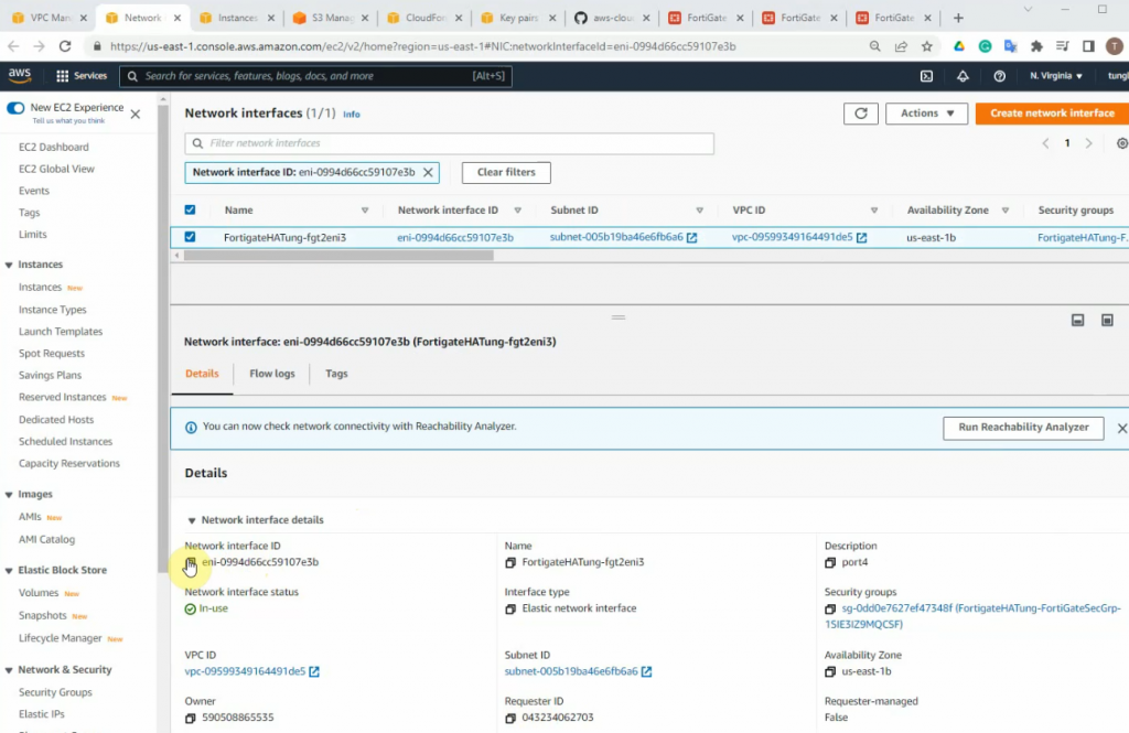
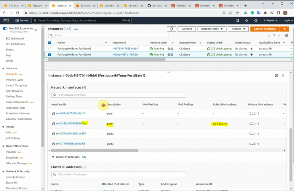
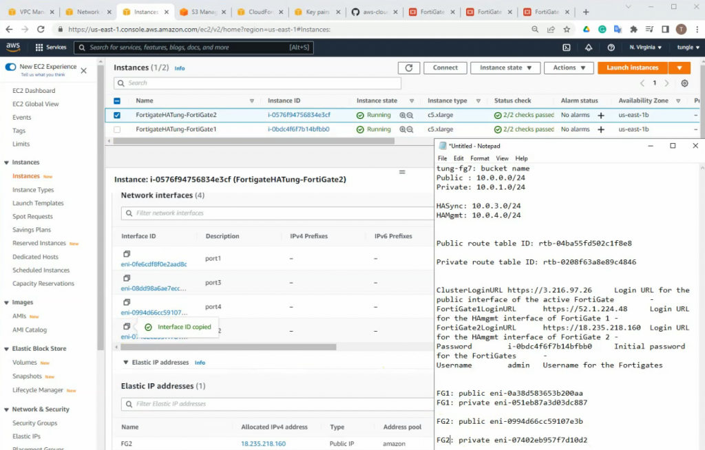
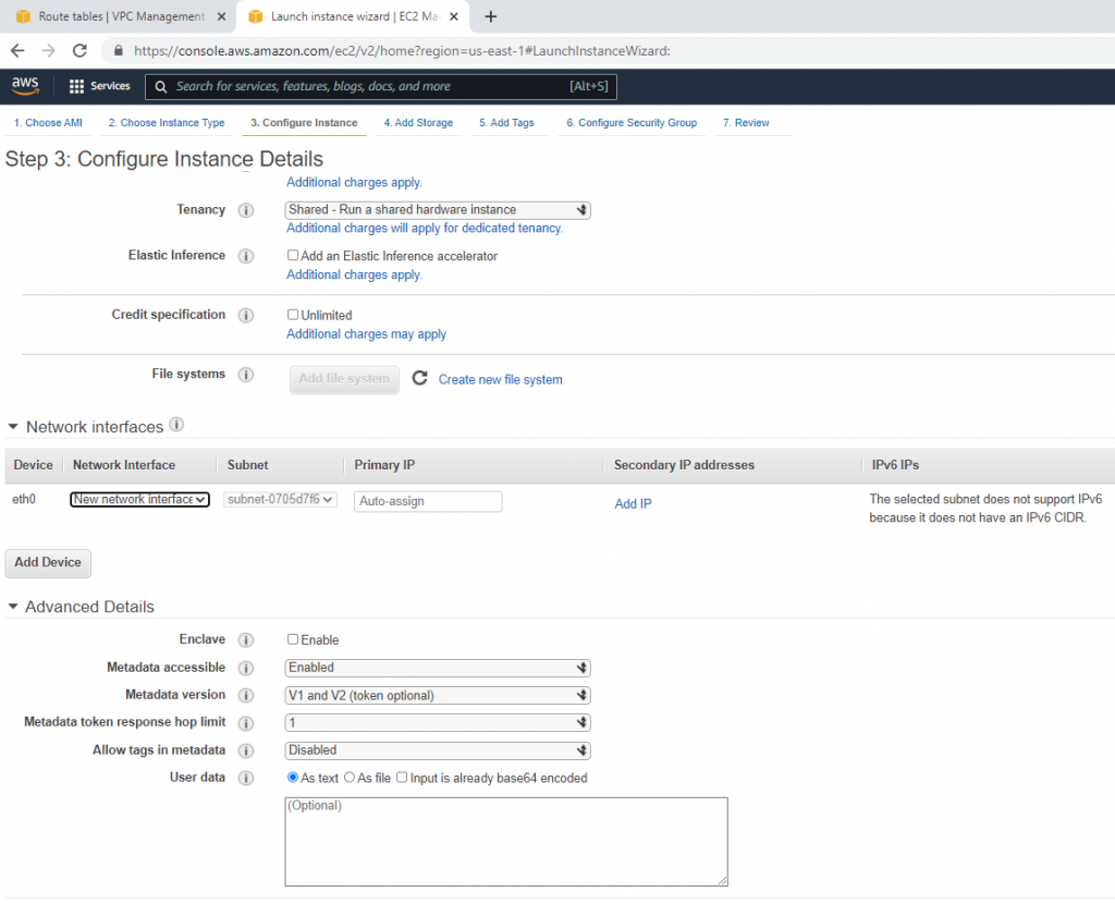
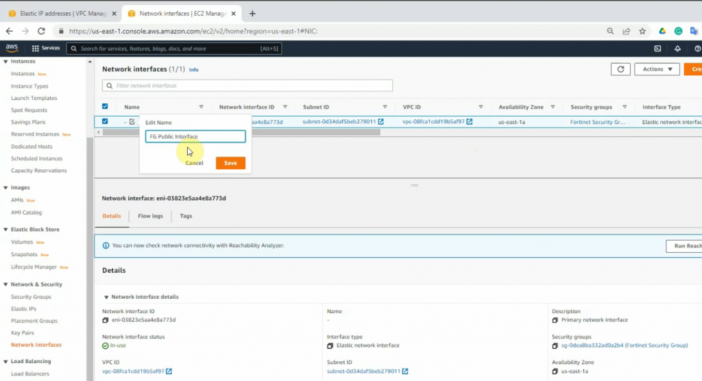
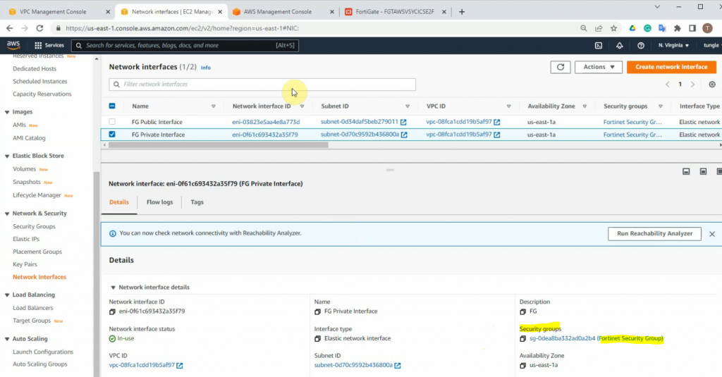
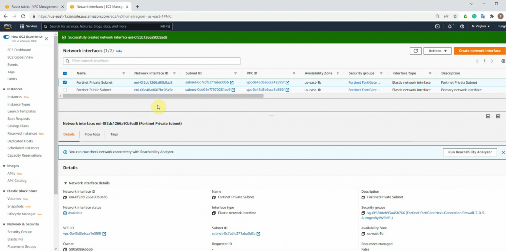
Go to Network interfaces, change the interface to FG Public Interface.
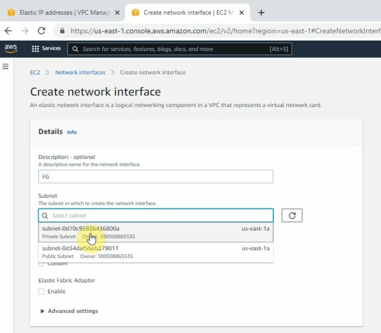
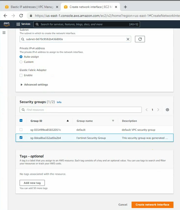
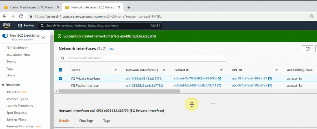
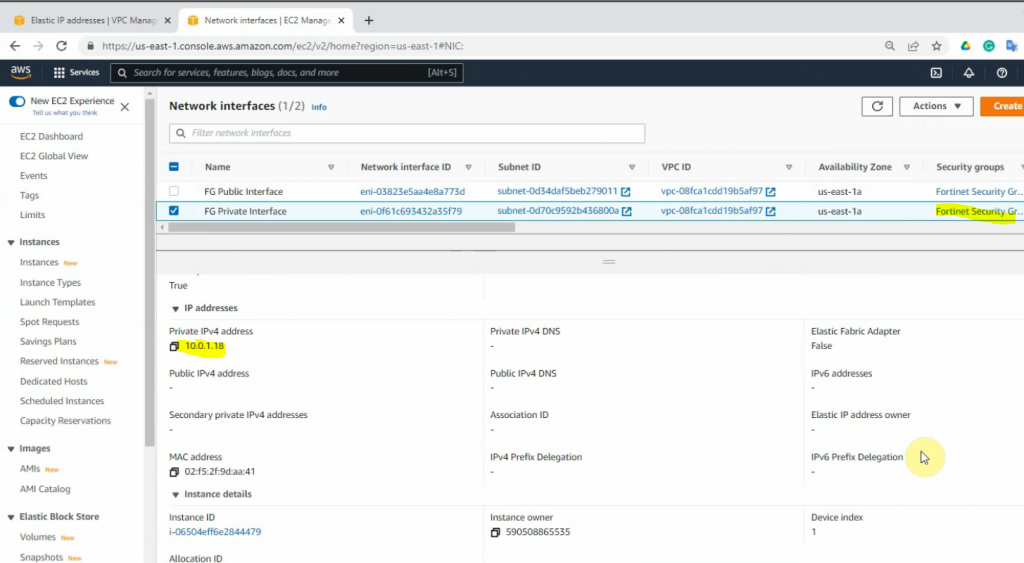
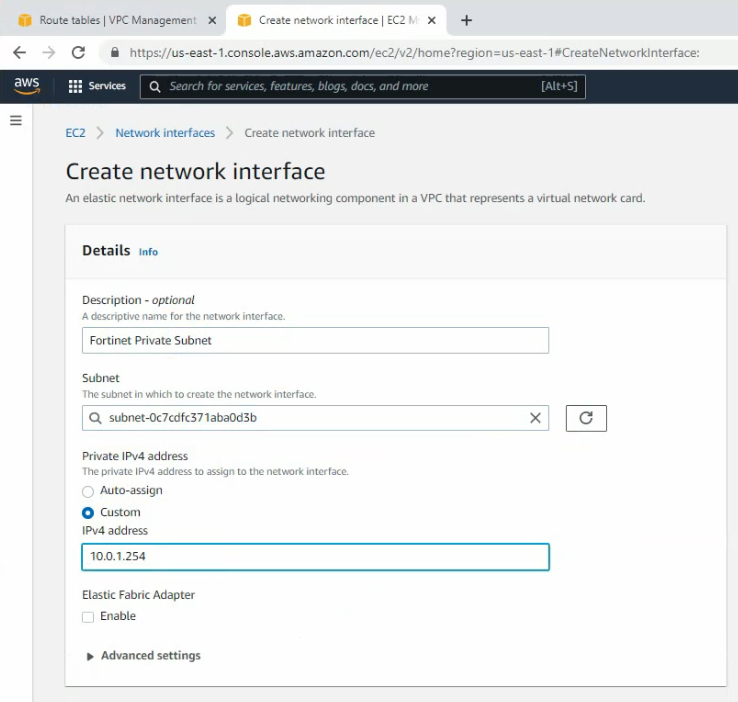
Create a new FG Private interface. Links to the private subnet and FortiGate Security Group.
Change to FG Private Interface.
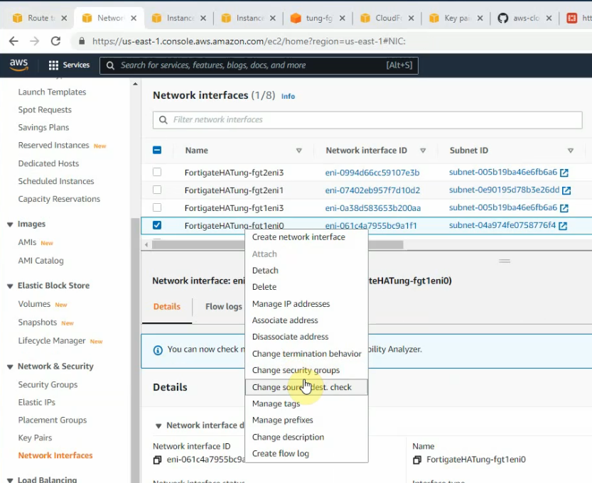
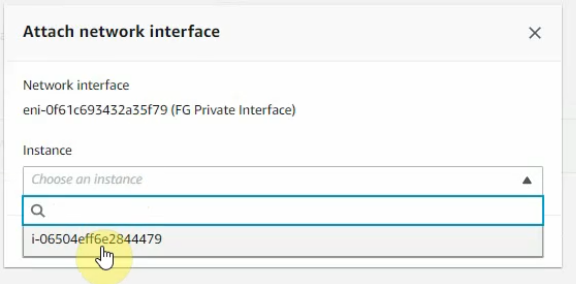
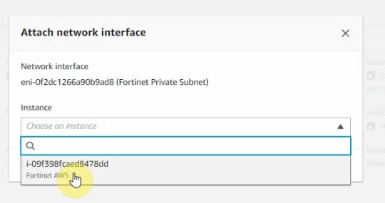
Select the FG private interface, choose Action on the top right-hand side and Attach this network interface to Fortinet EC2.
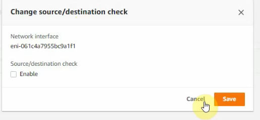
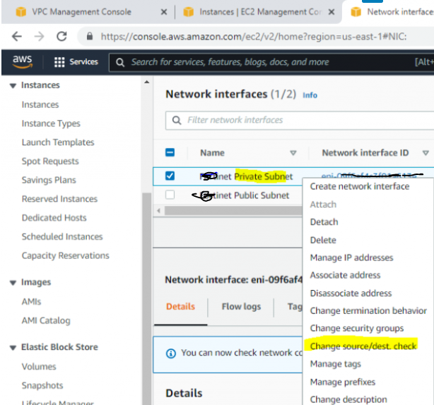
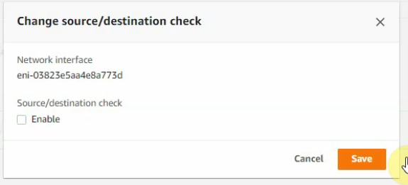
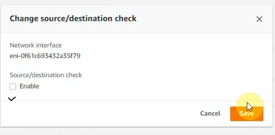
Right-click on both FG Public and Private interfaces, and disable “Change source/dest check” on both interfaces to allow NAT traffic on these interfaces.
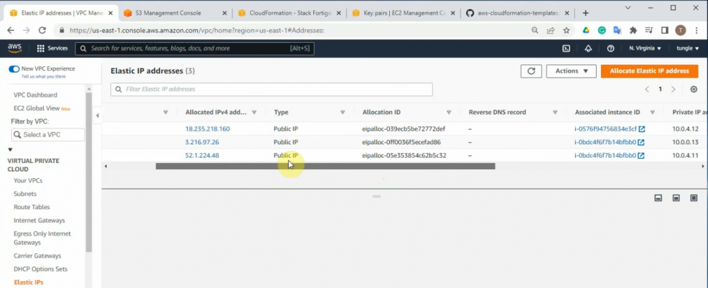
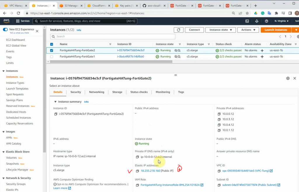
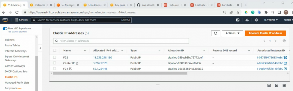
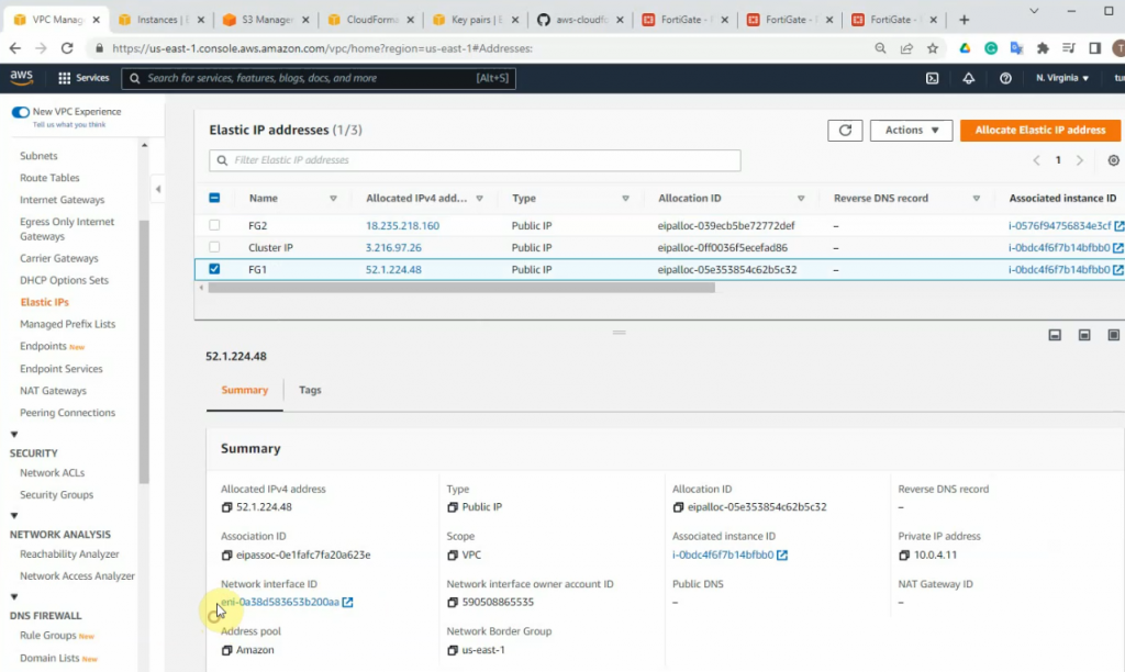
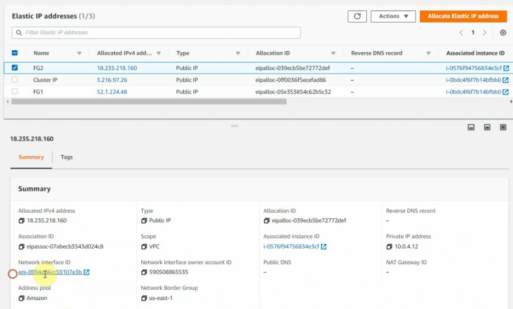
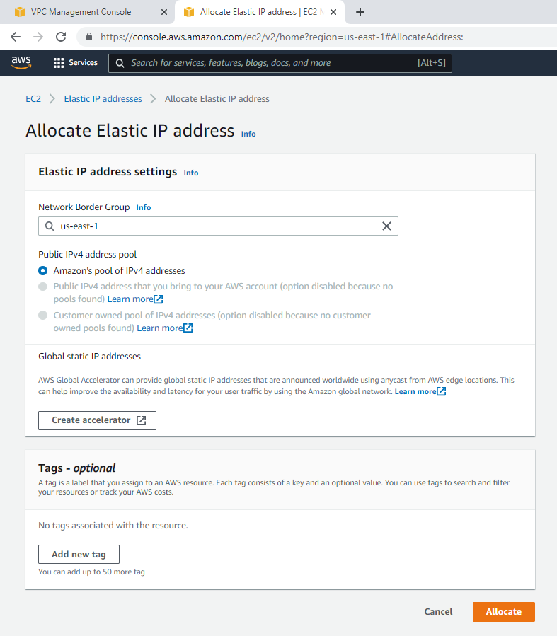
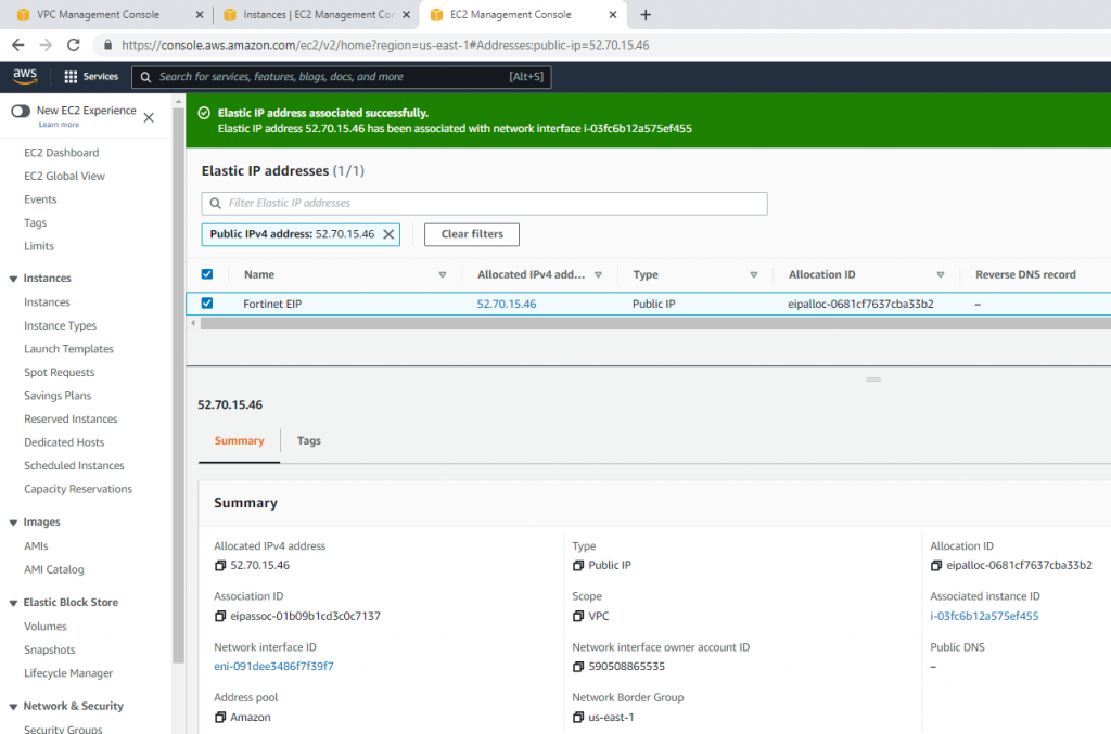
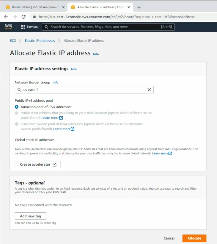
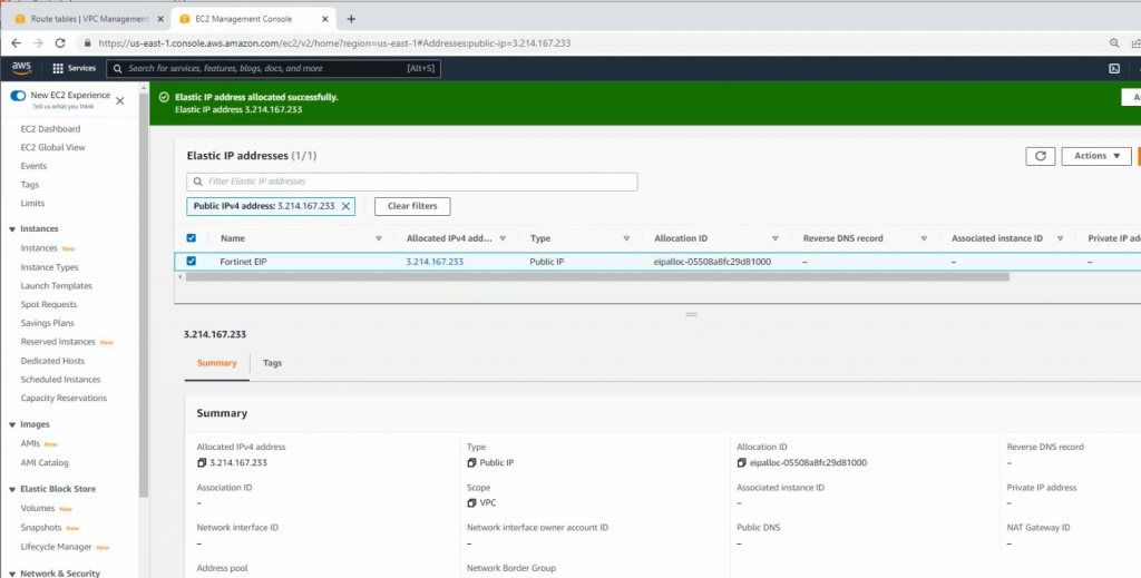
Create a new Elastic IP address.
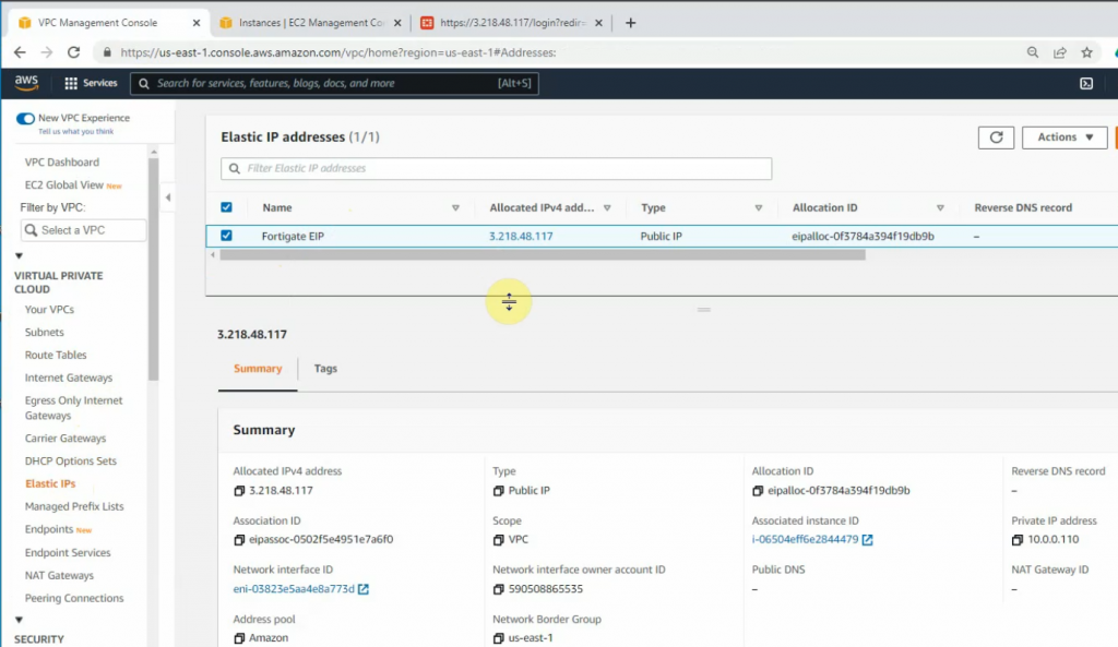
Change to Fortinet EIP.
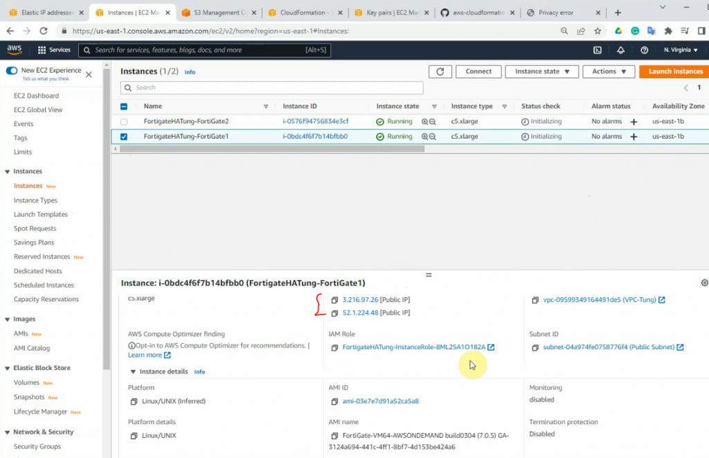
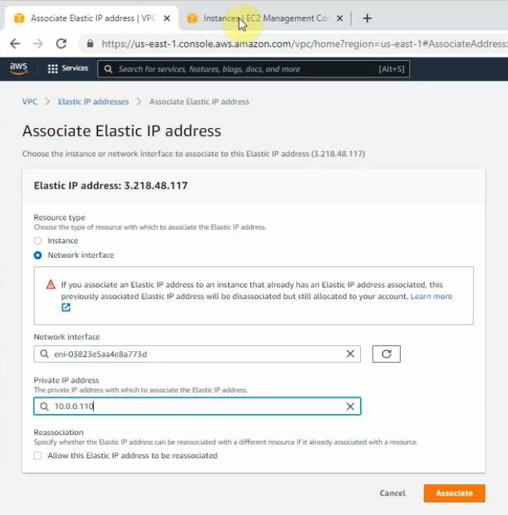
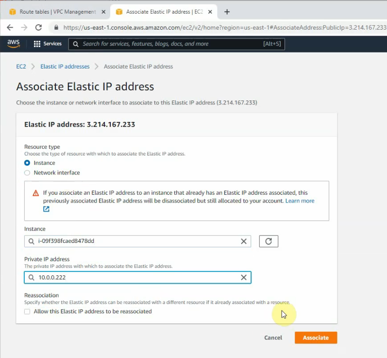
Associate this Elastic IP address to Fortinet EC2.
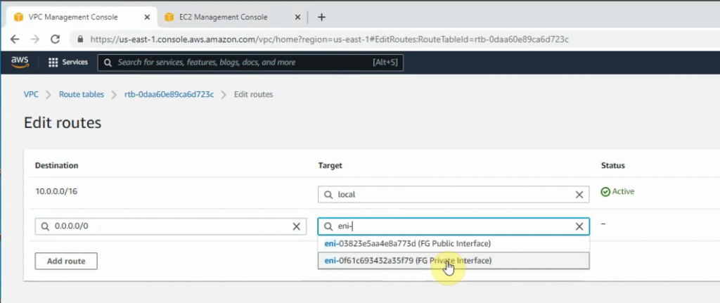
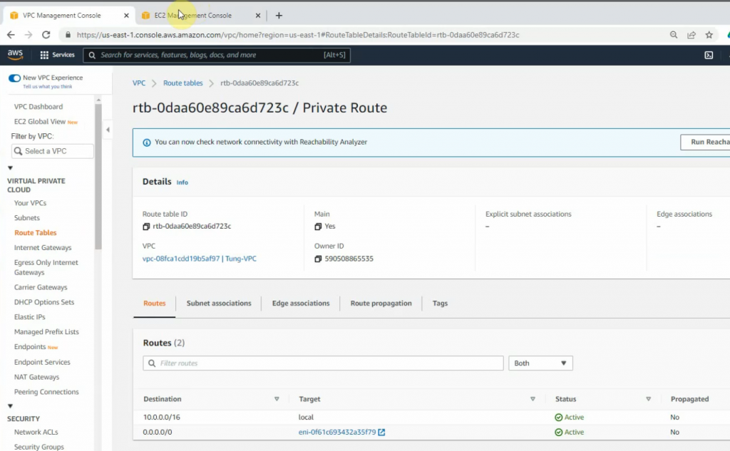
Back to Route tables, add a new route 0.0.0.0/0 to FG private interface.
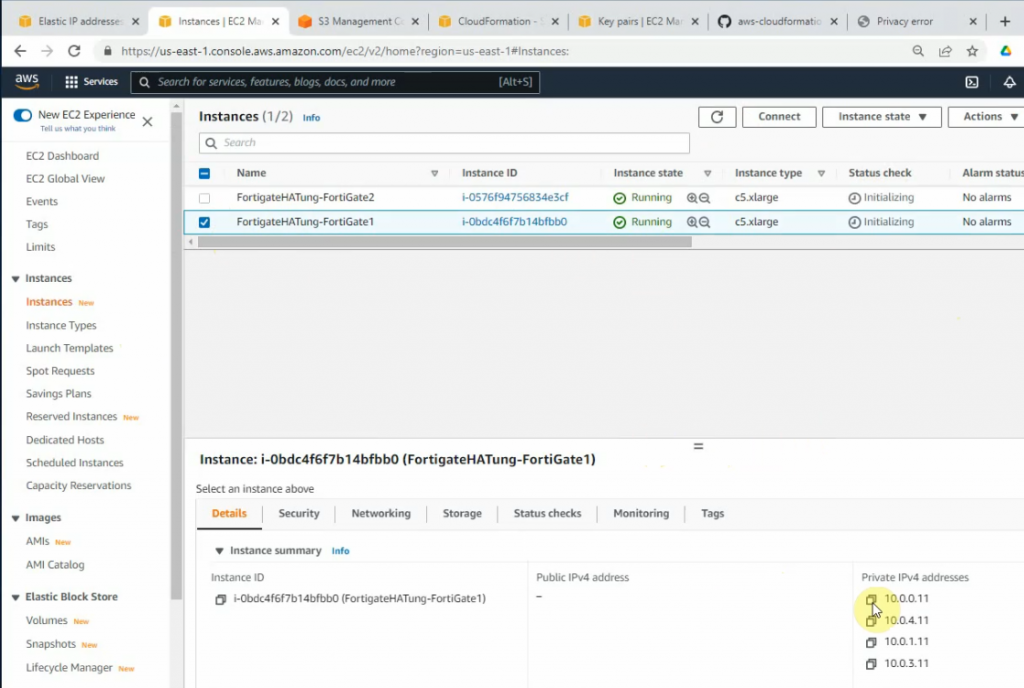
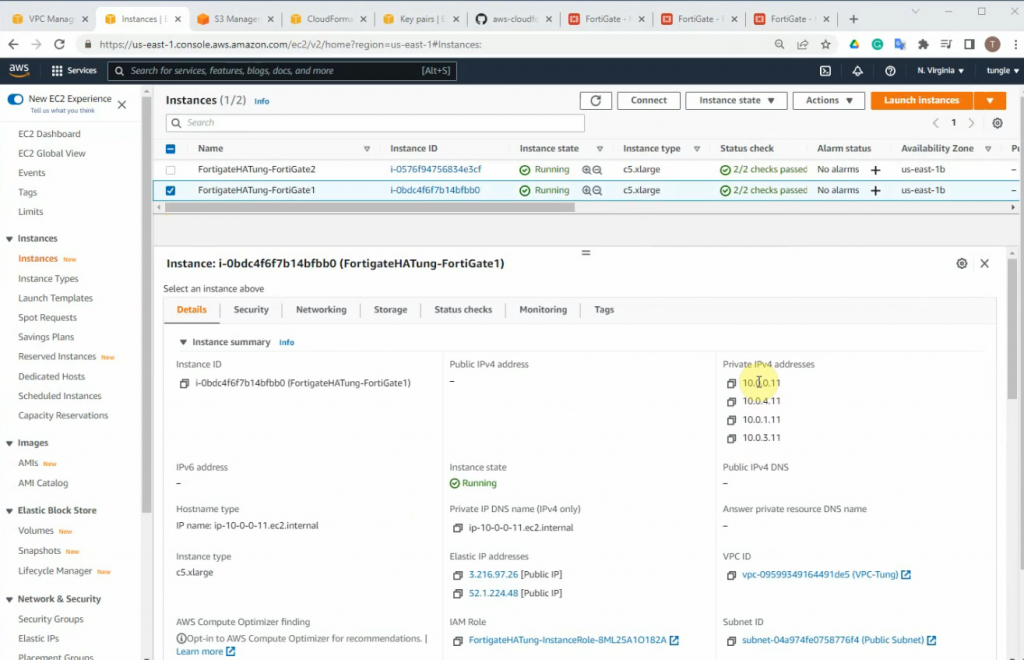
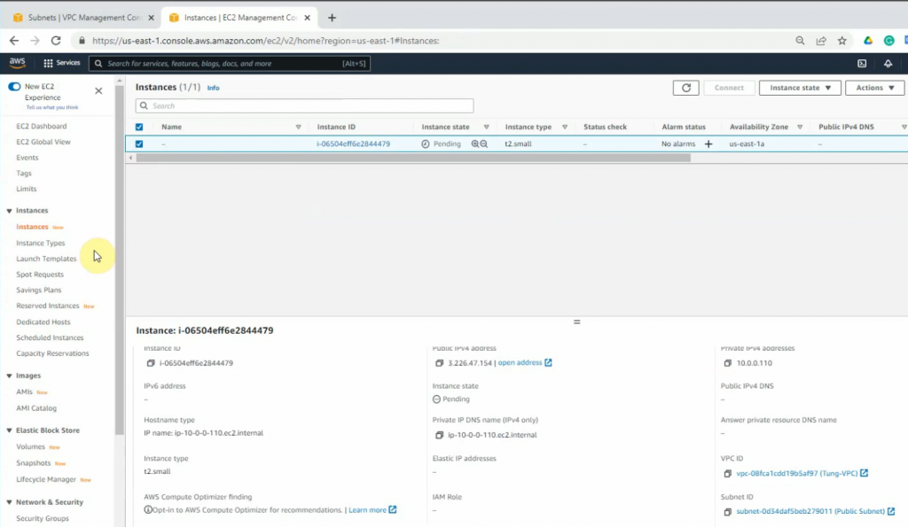
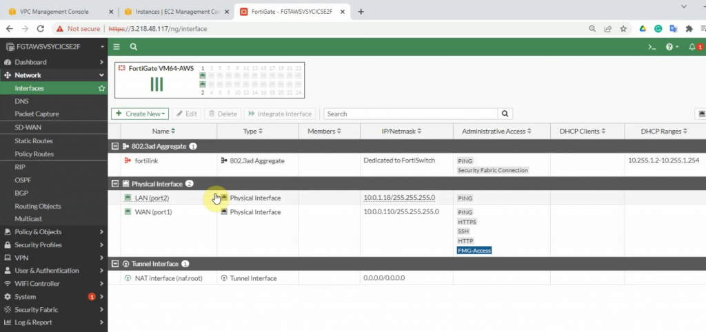
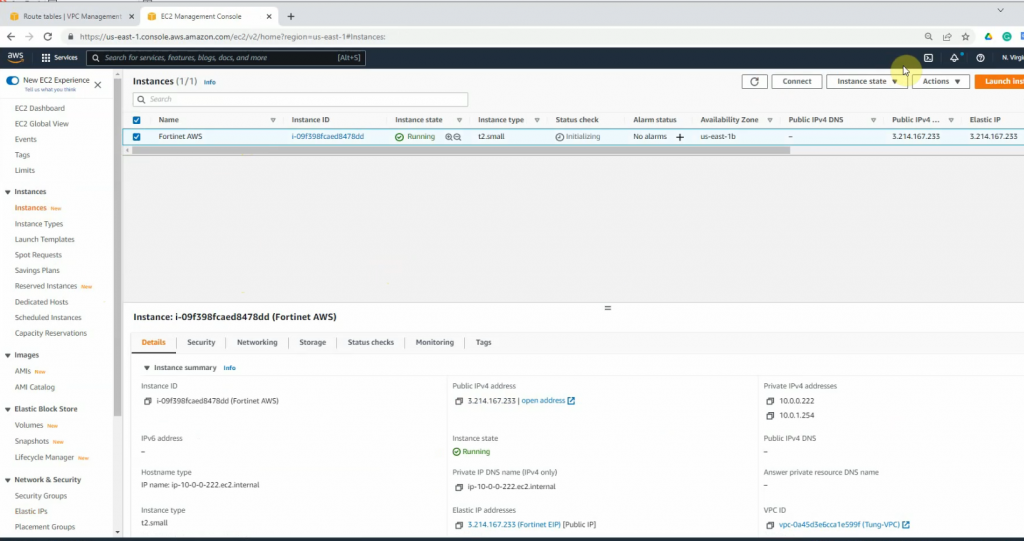
Now, Fortinet has two interfaces. One is Private, and another one is Public.
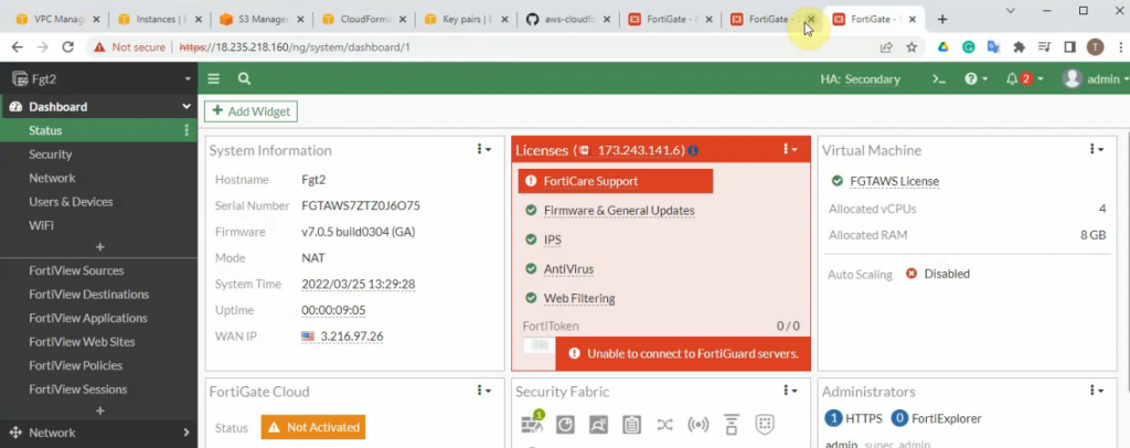
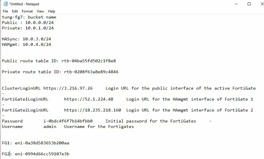
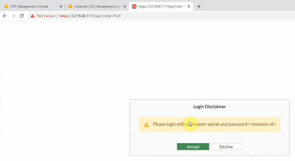
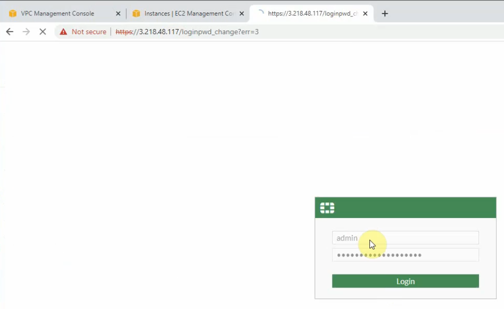
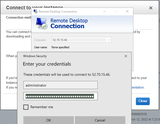
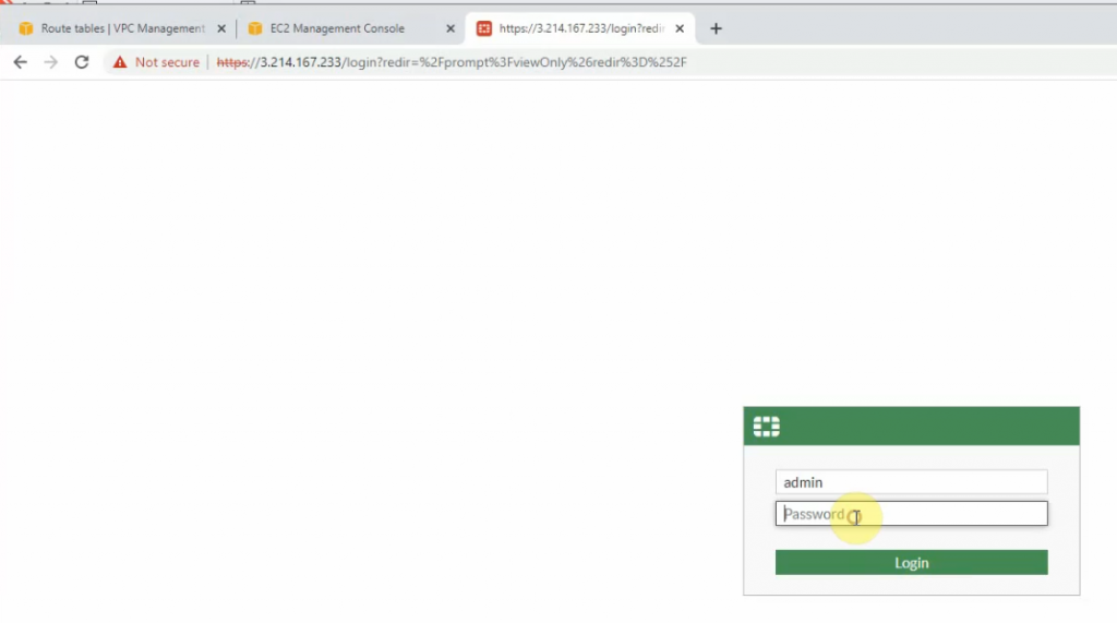
Copy the Elastic IP address and paste it to your web browser to access the FortiGate management interface.
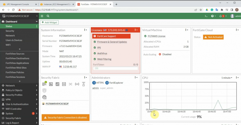
Access Fortinet via the Internet.
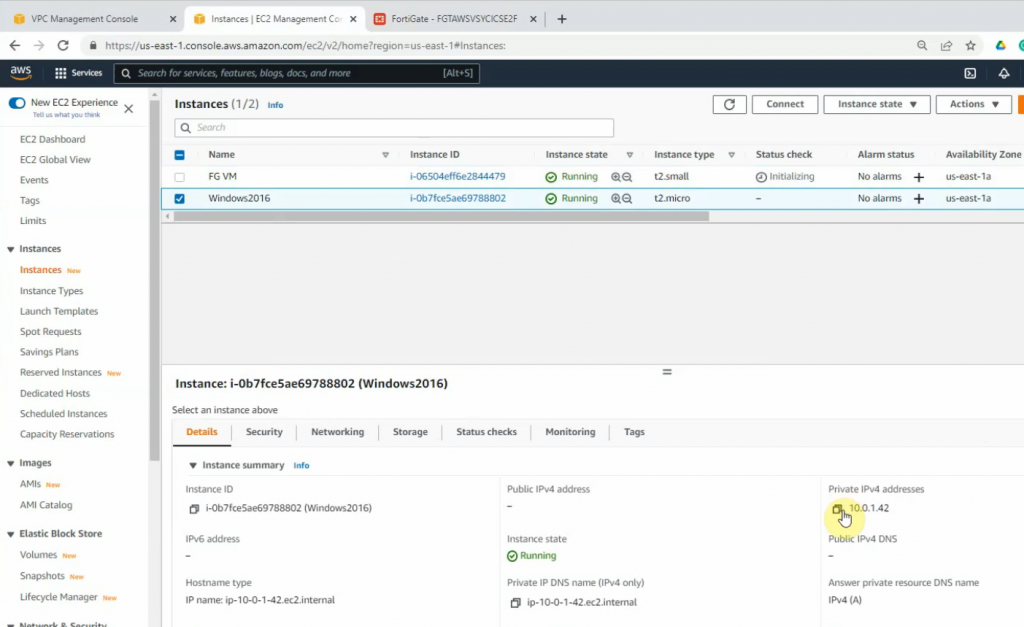
+ Launch a new Windows VM EC2 instance on your VPC.
Network: Your VPC
Subnet: Private subnet
Auto-assign Public IP: Disabled. We will access RDP to the machine via DNAT on FortiGate.
On the Security Group setting, add two lines to allow RDP and ICMP traffic to the machine.
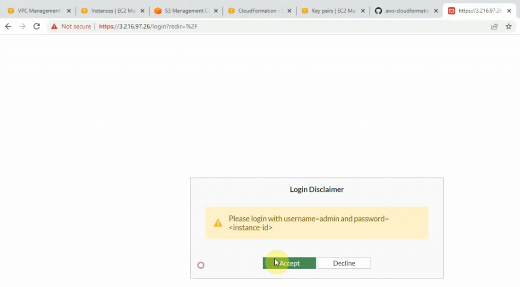
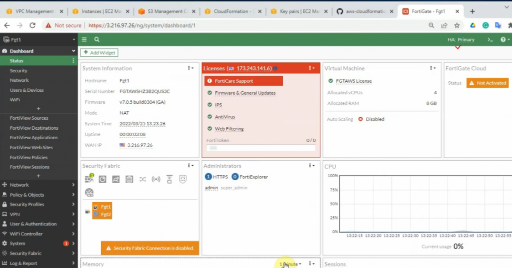
+ Login to Fortinet.
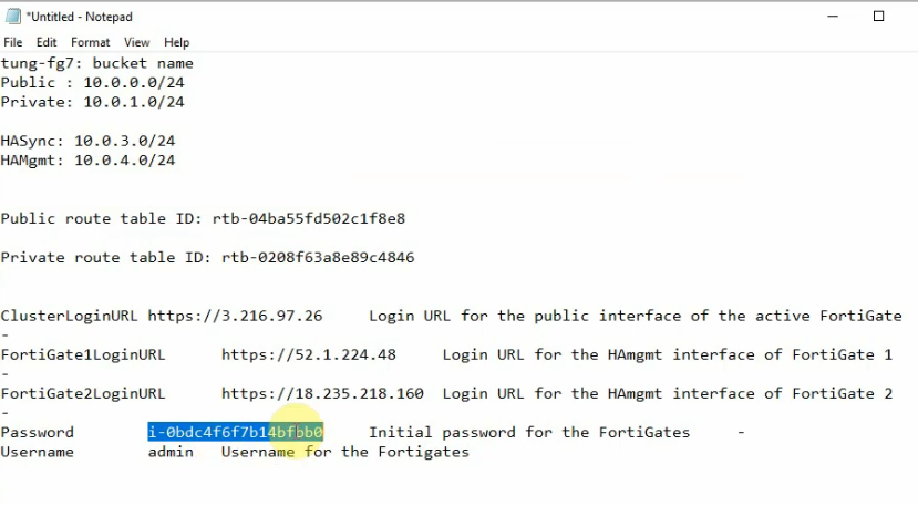
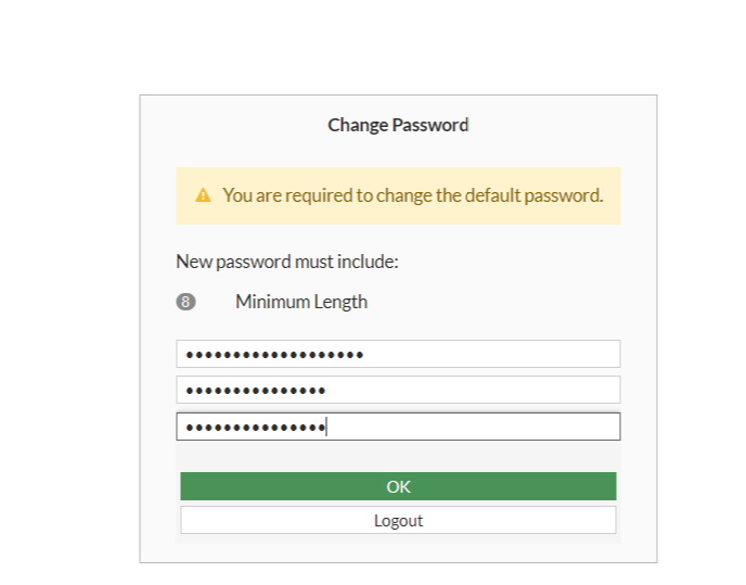
Copy the FG instance and paste it to password login.
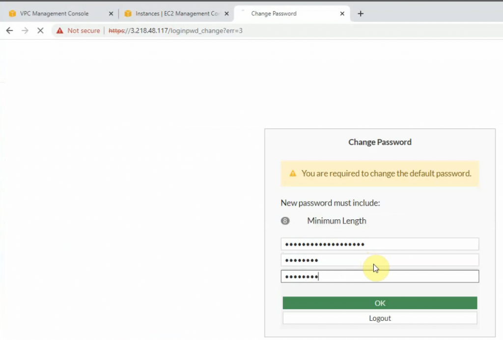
Change the password to login to Fortinet.
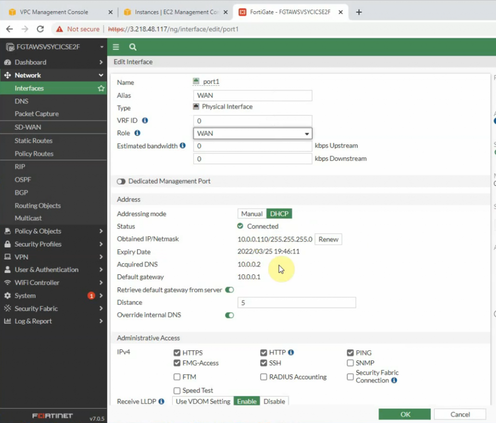
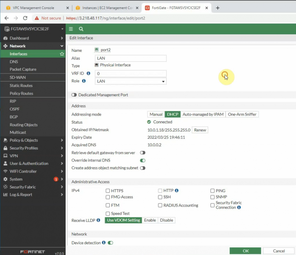
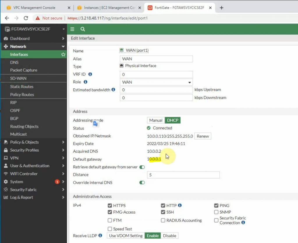
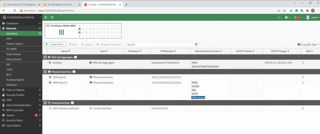
Edit WAN and LAN interface setting.
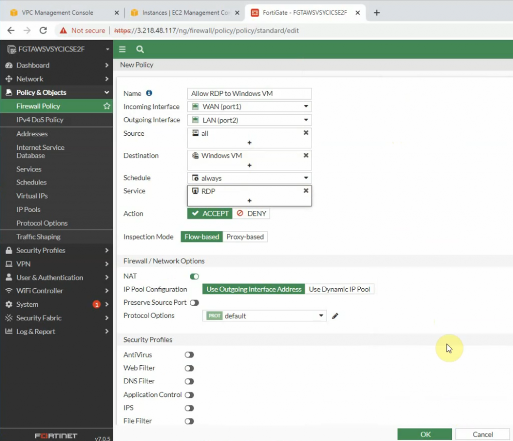
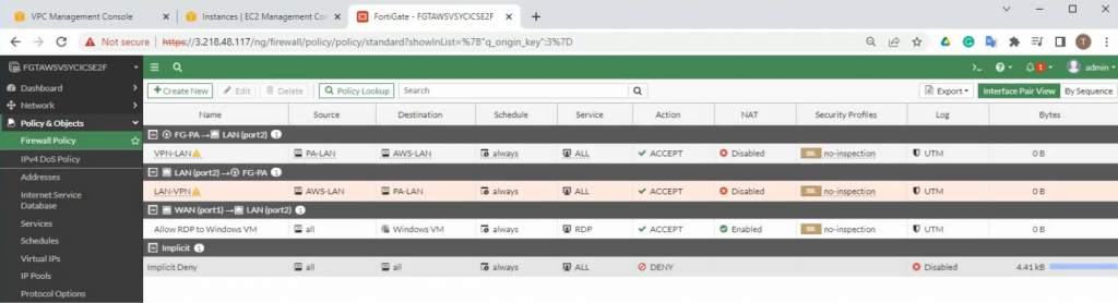
Back to Fortinet to configure Firewall Policy to allow RDP traffic from the Internet to the Windows VM machine.
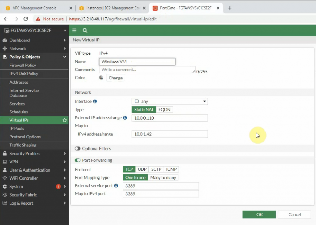
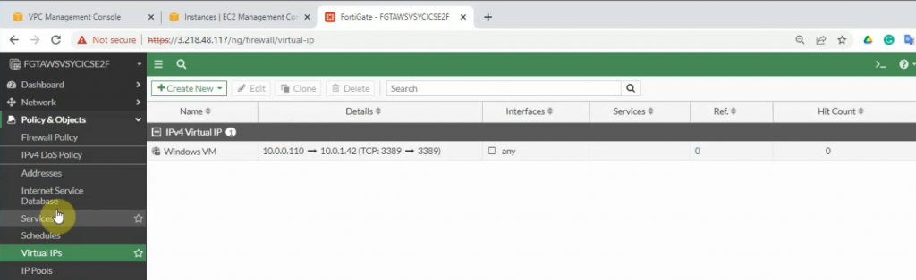
Configure port forwarding to allow traffic from the Internet to Windows 2016 VM instance on AWS.
External IP address: IP address of FG on the public subnet
Map to IPv4 address on the private subnet is IP address of Windows VM computer.
The external service port and map to IPv4 port is 3389.
Allow inbound traffic from WAN to this machine.
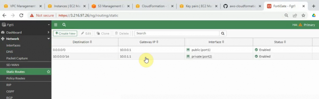
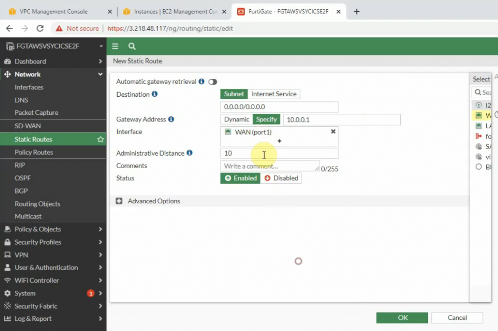
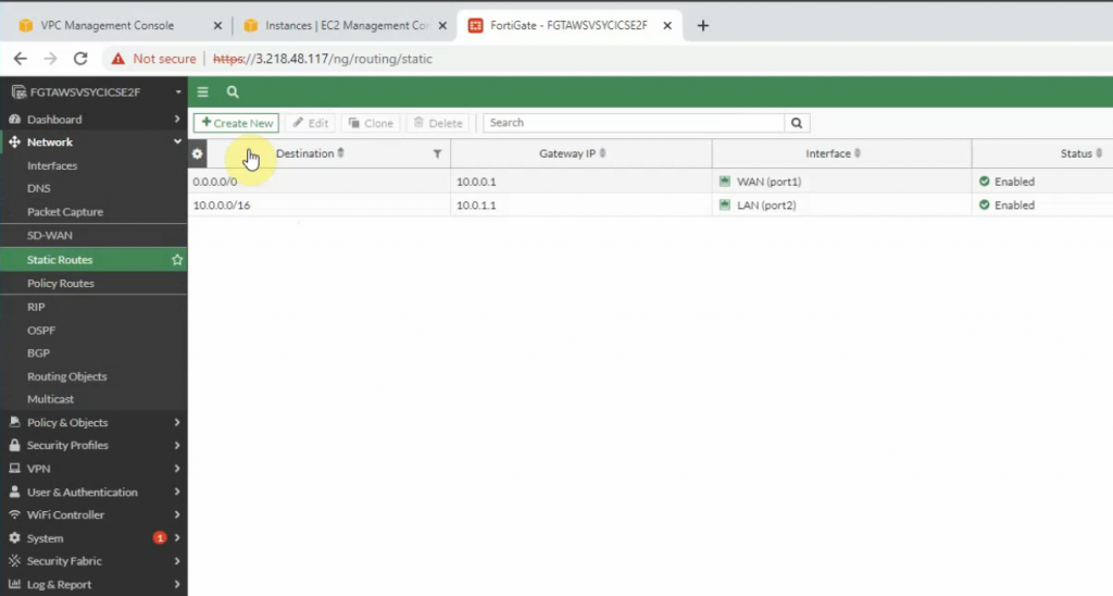
Create both static routes to allow a private subnet to access outside.
Creating new static routes for the private subnet from 10.0.0.0/16 to 10.0.1.1 that is the default gateway on the private subnet.
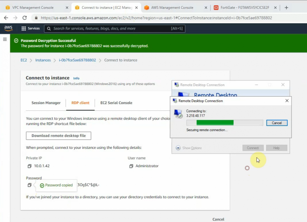
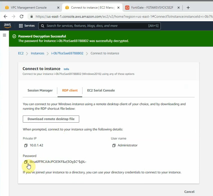
Try to access the machine.
Load private key to decrypt Windows password.
Access RDP to Windows 2016 instance on AWS.
Now we can see the RDP traffic via Fortinet.
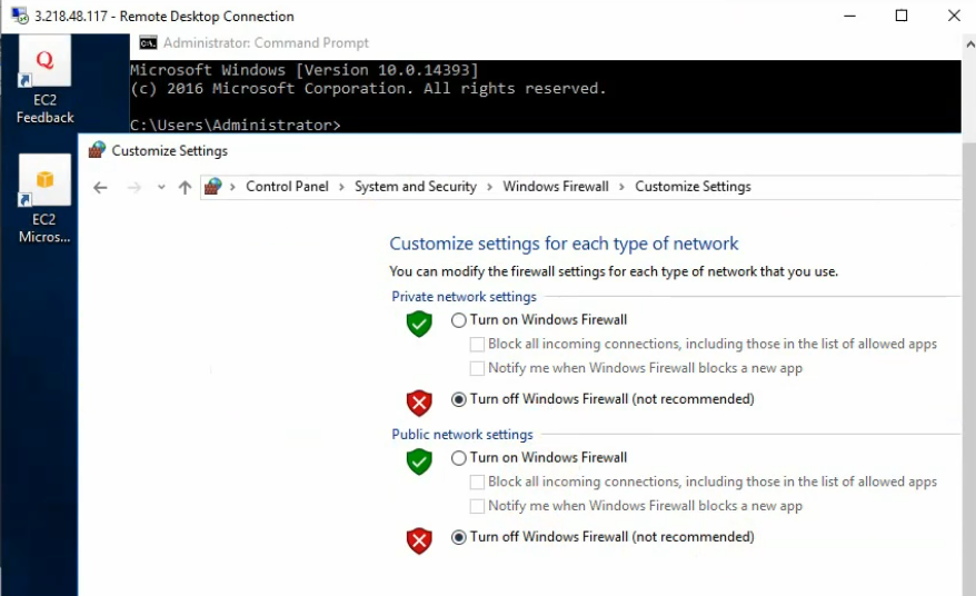
Disable Windows Firewall to allow ICMP traffic to that machine on Palo Alto private subnet.
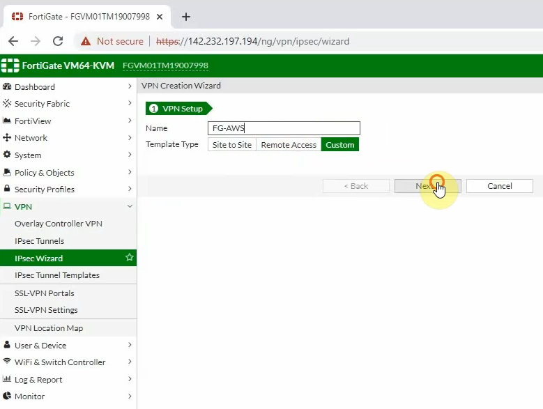
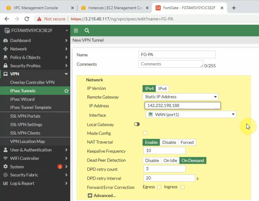
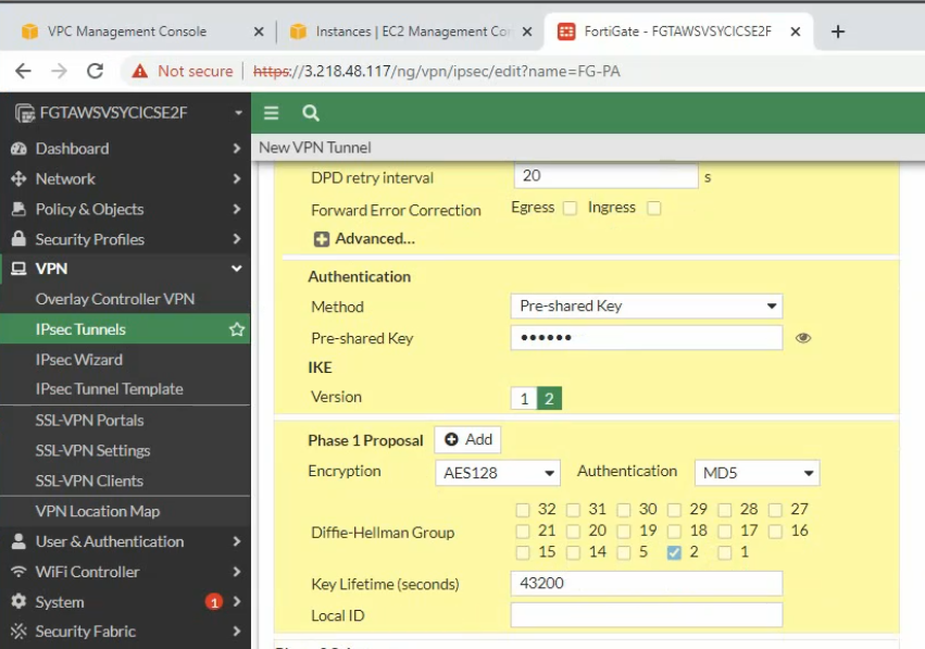
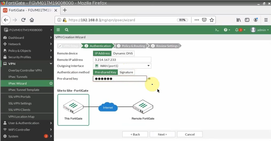
Configure IPSEC site to site wizard. Choose Custom.
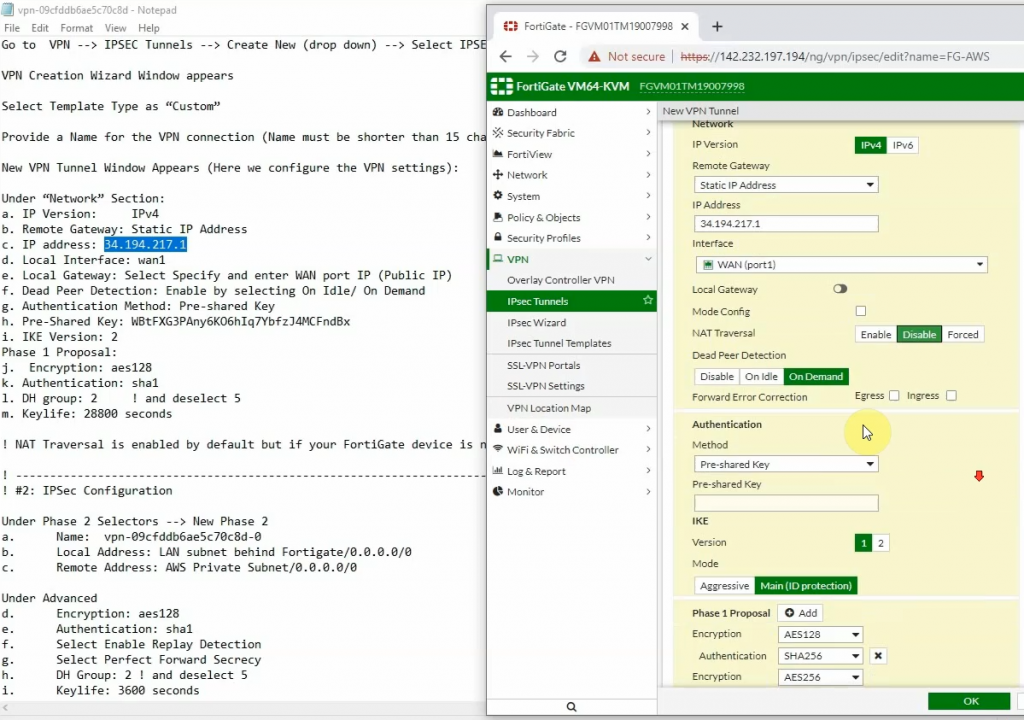
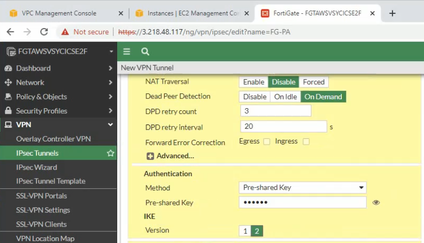
Enter IP address of public interface of PA. Disable NAT traversal, enter the pre-shared key and choose the IKE v2.
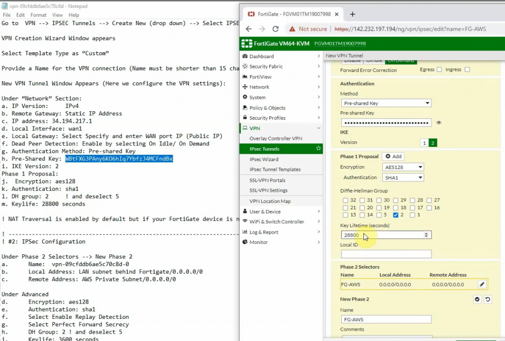
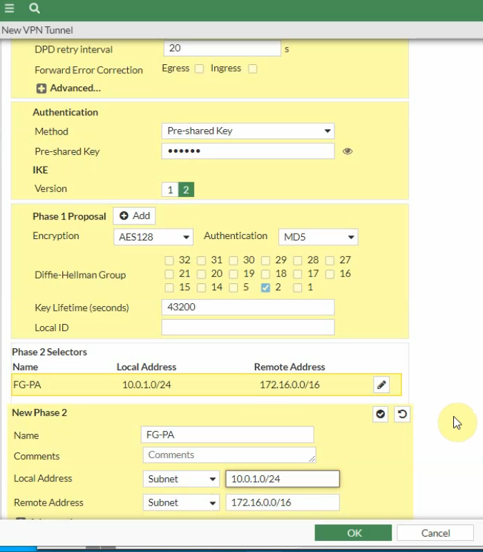
Phase 1 and Phase 2 settings need to match with the Palo Alto setting.
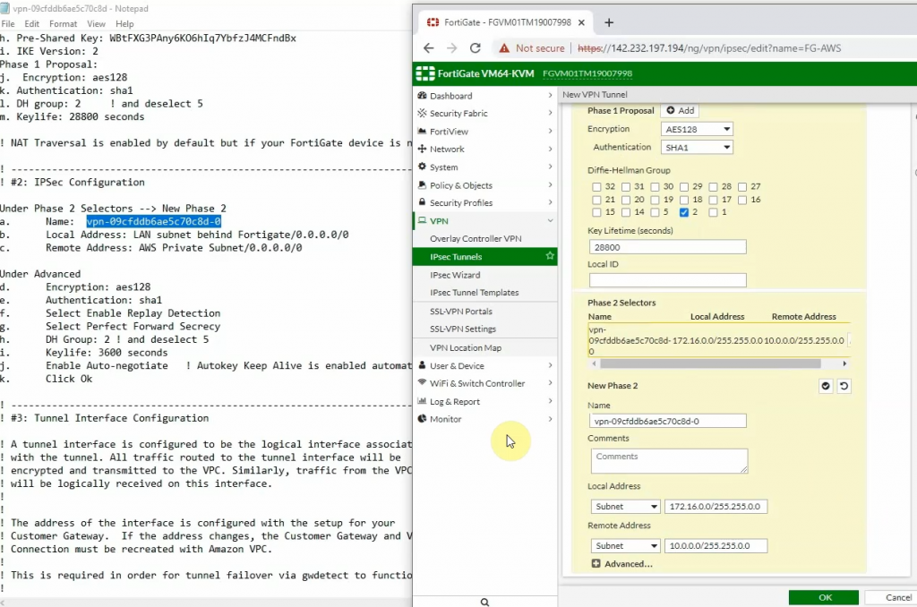
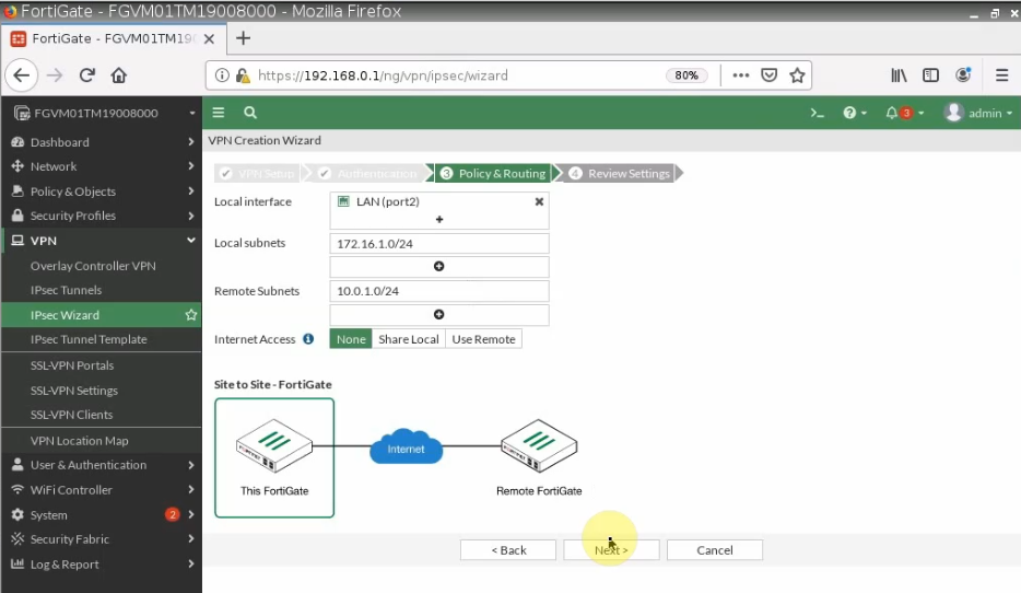
Local Address: the private subnet of FG: 10.0.1.0/24
Remote Address: PA LAN subnets: 172.16.0.0/16
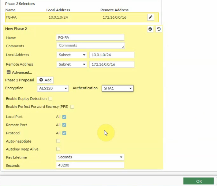
Click the Advanced tab. Change the setting to match with PA Phase 2 setting
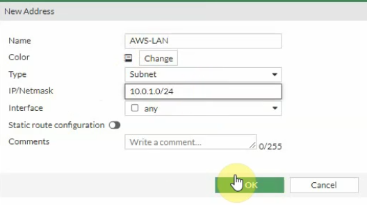
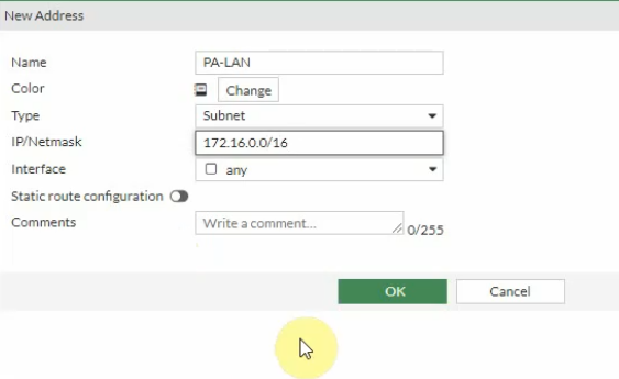
Create Fortinet LAN and PA LAN subnet network addresses.
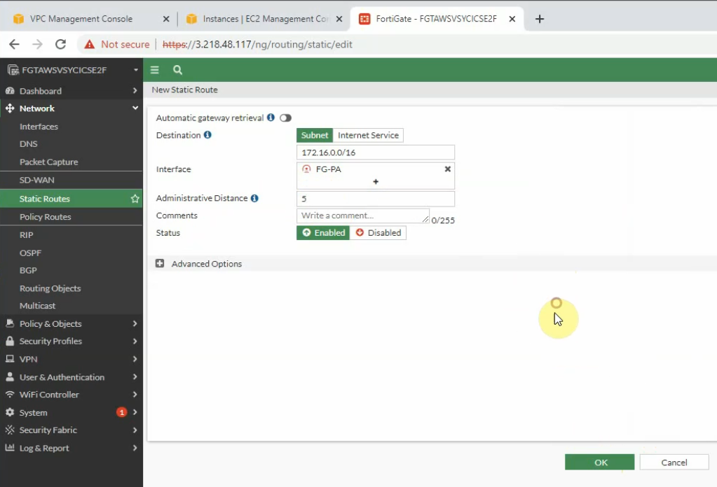
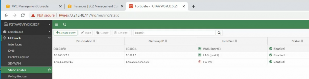
Create a static route on Fortinet to allow private subnet traffic to the Palo Alto LAN subnet.
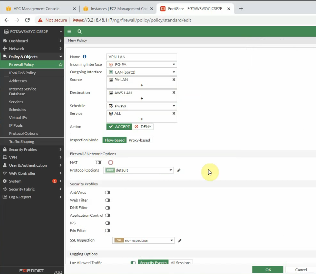
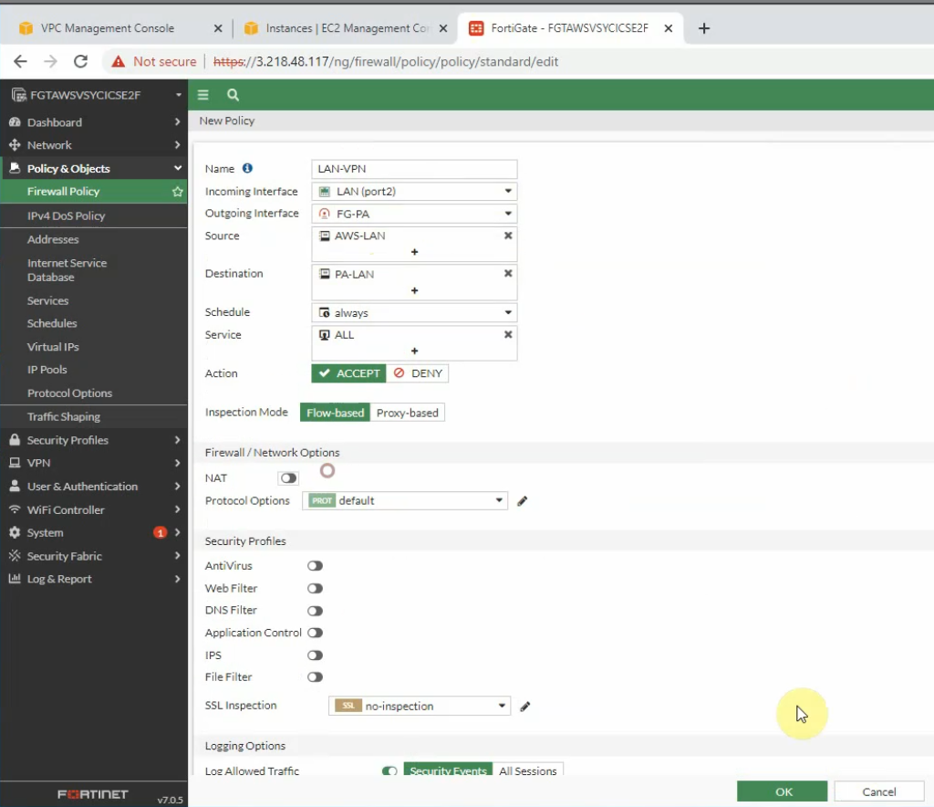
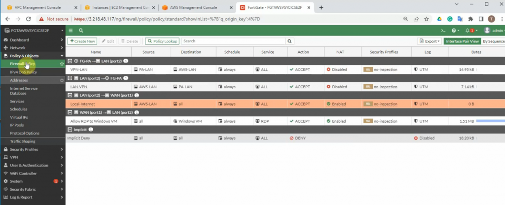
Create a Security Policy to allow traffic from the Fortinet LAN subnet to the PA LAN subnet. Remember to uncheck NAT setting on access rules from AWS LAN to PA LAN and vice versa.
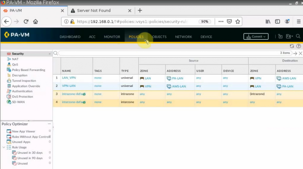
PA LAN subnet to AWS LAN subnet.
AWS LAN subnet to PA LAN subnet.
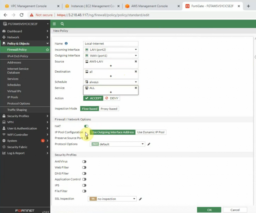
Create a new access rule to allow the FG LAN subnet to access the Internet.
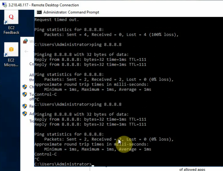
Ping 8.8.8.8 from Windows 2016 VM instance.
+ Configure PA.
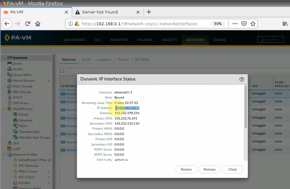
Setting the IP address for e1/1 is DHCP, and assign an IP address for e1/2 is 172.16.1.254/24
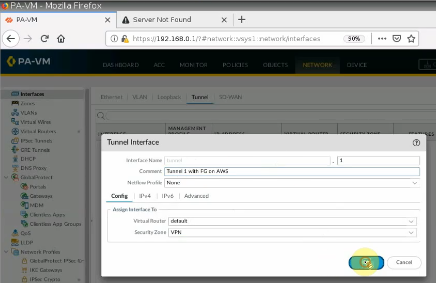
Create a tunnel interface: tunnel 1.
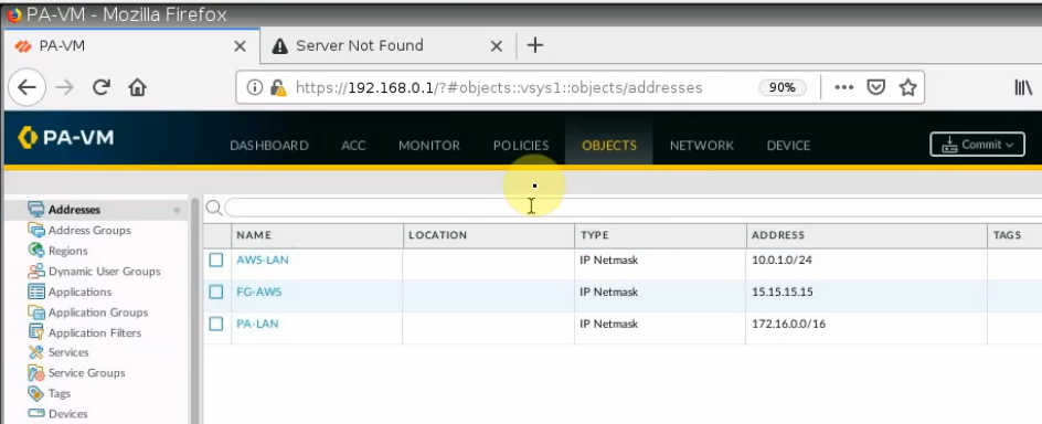
Create network objects for FortiGate, PA LAN, and AWS LAN.
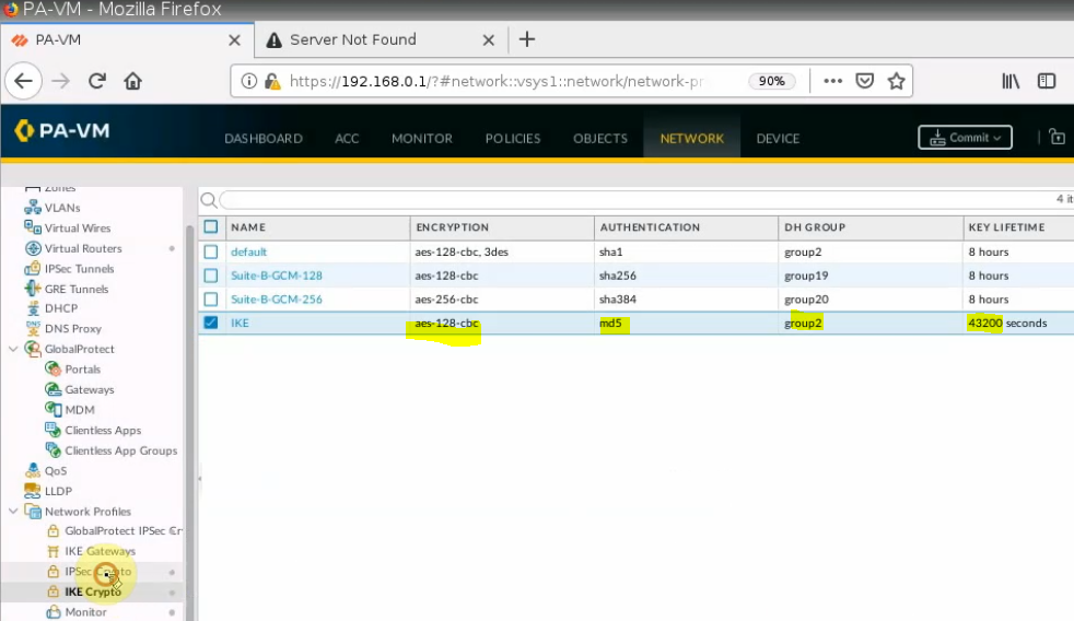
Create IKEC Crypto.
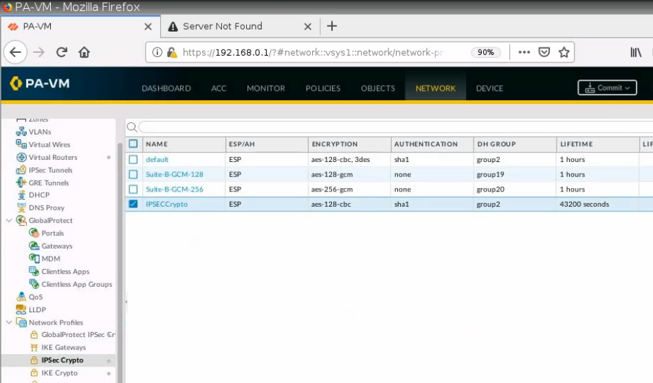
Create an IPSEC Crypto.
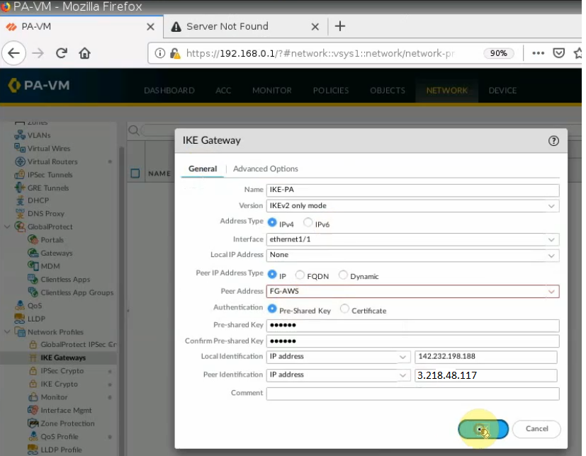
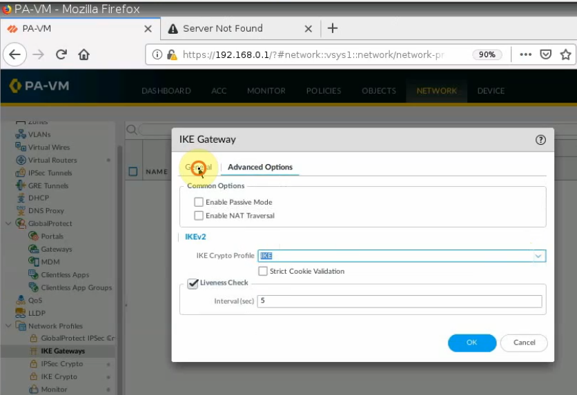
IKE Gateway.
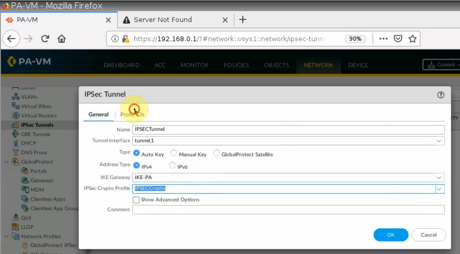
IPSEC tunnel.
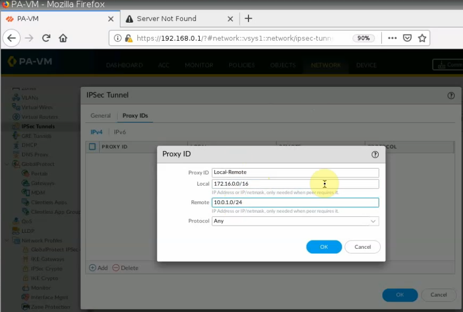
On Proxy ID tab.
Local: PA LAN subnets.
Remote: AWS LAN subnet.
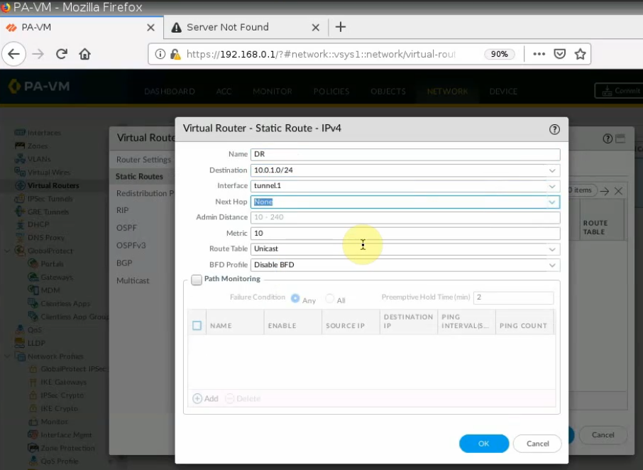
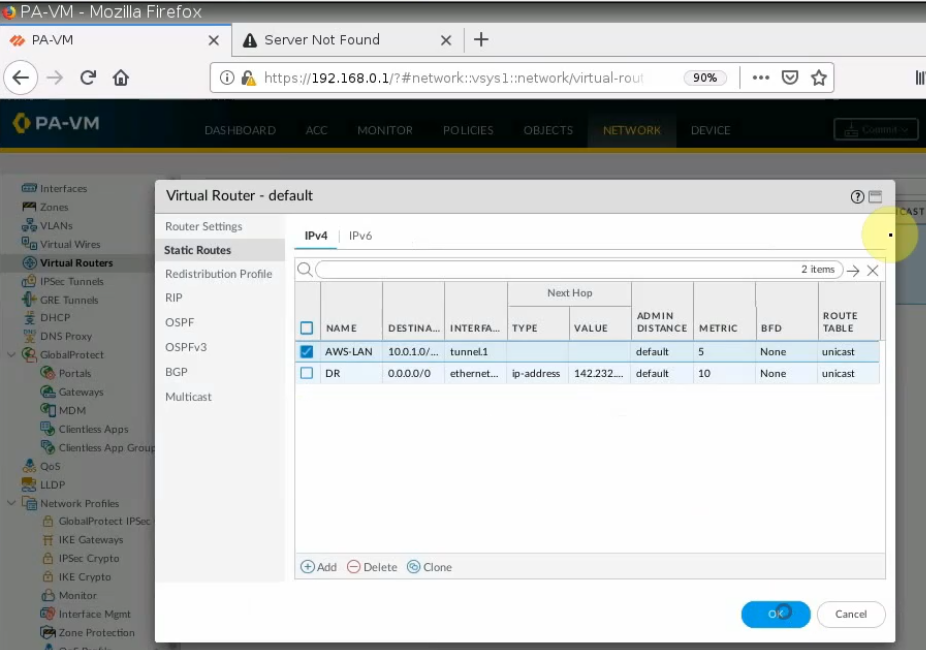
Create a Static Route from PA LAN to Fortinet LAN on AWS.
Create both Security Policies to allow traffic from PA LAN subnet to AWS LAN subnet.
Remember to click “Commit” button to apply the new settings on PA.
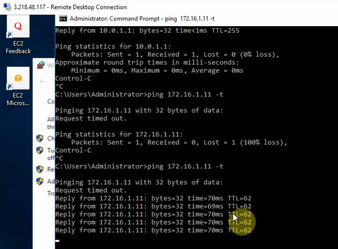
From Windows 2016 VM instance, pings a machine on PA LAN subnet.
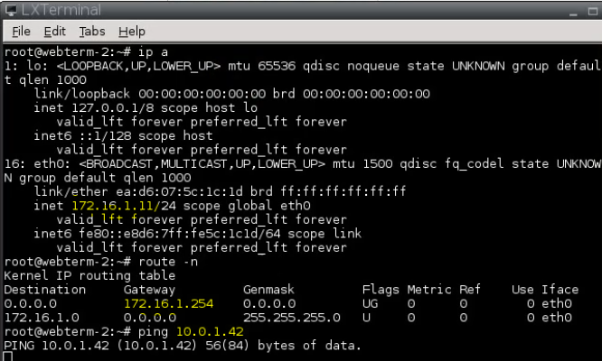
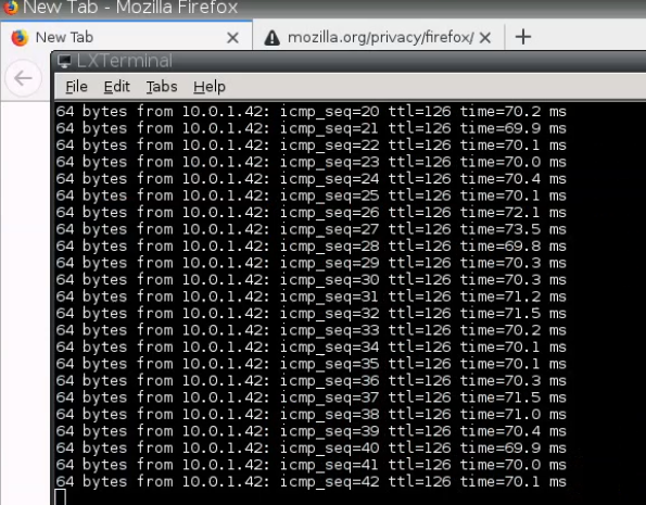
+ Pings from PA LAN subnet to AWS LAN subnet.
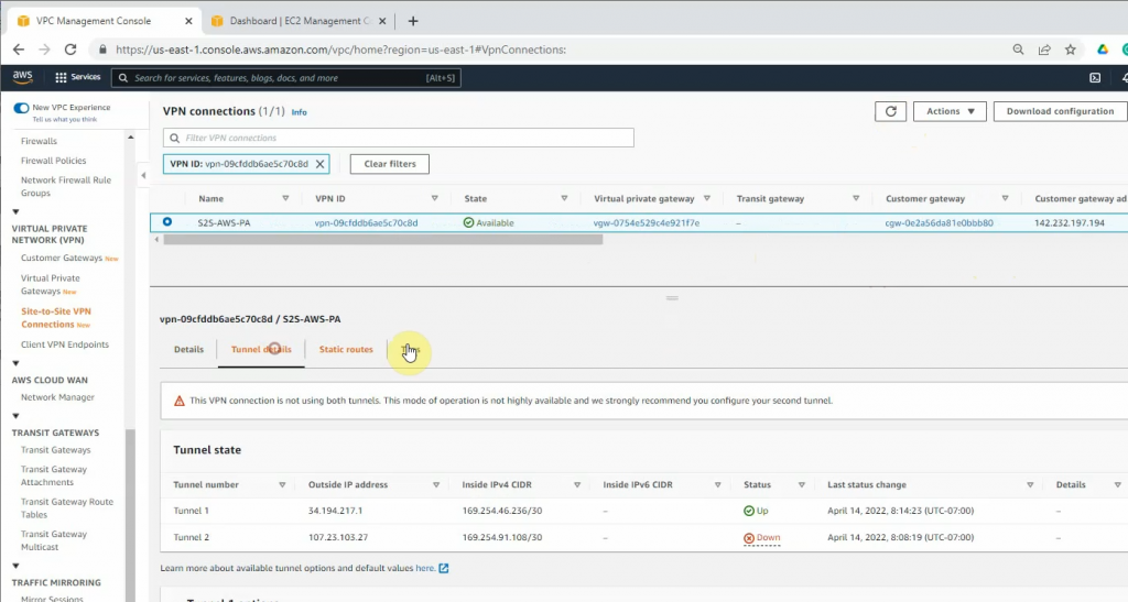
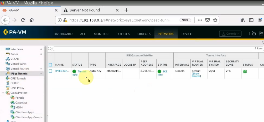
On PA, a tunnel is up.
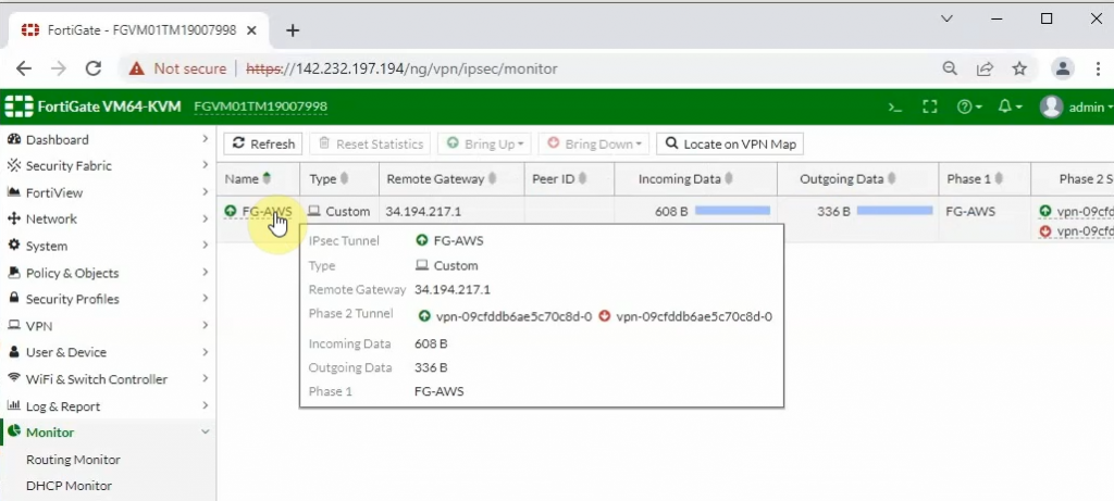
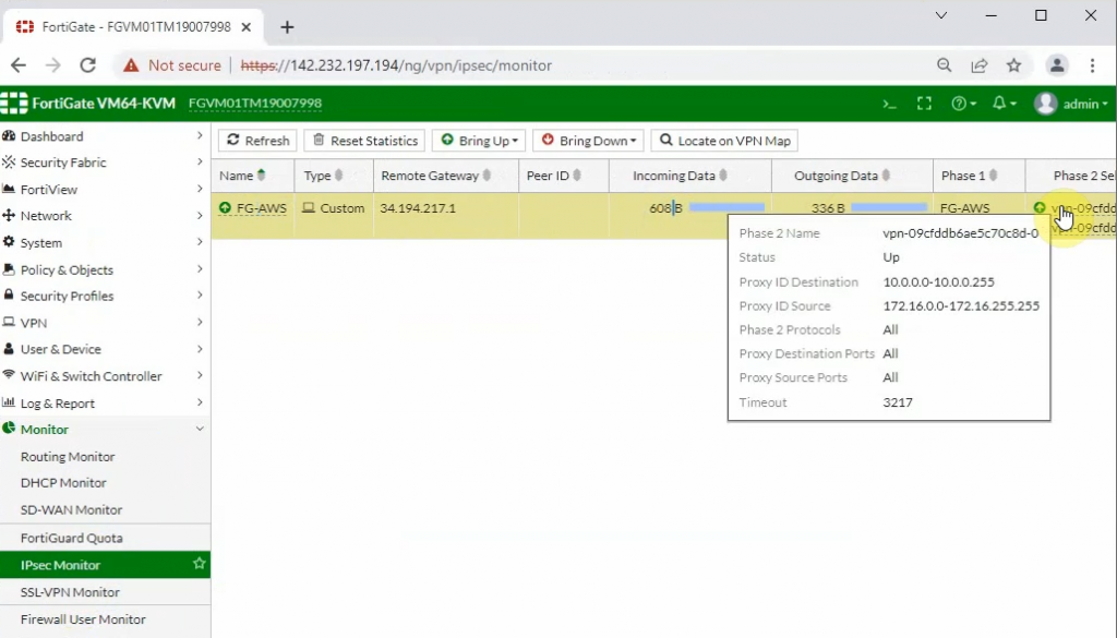
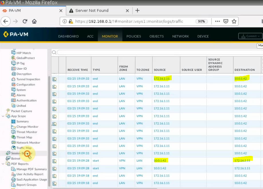
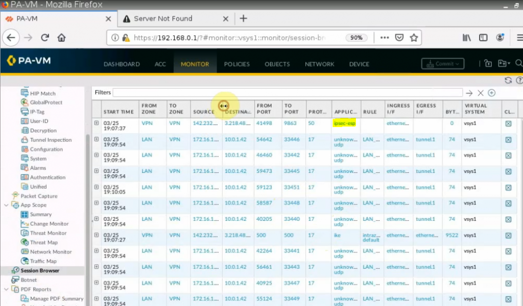
Monitoring to see the traffic on both sites.
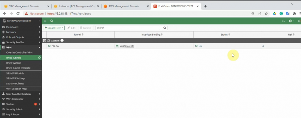
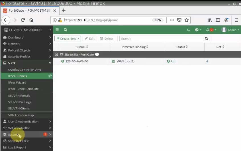
On FortiGate.
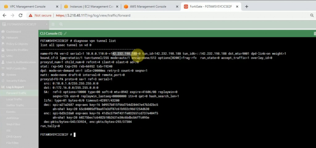
An IPSEC VPN site-to-site tunnel is up.
diagnose vpn tunnel list
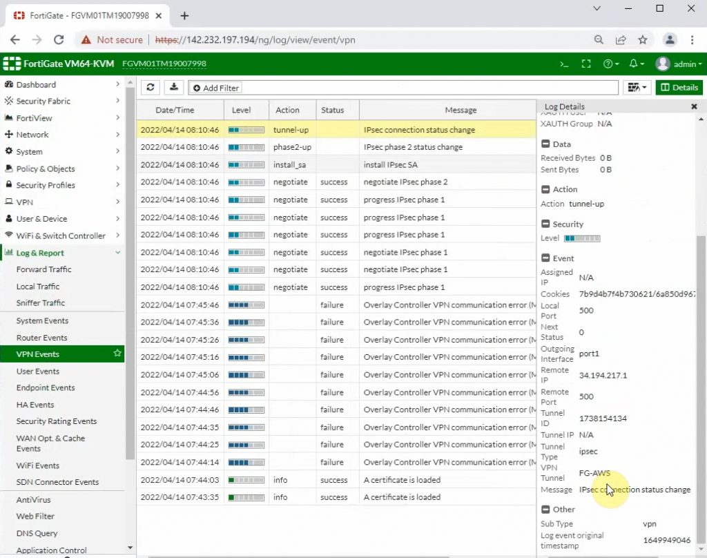
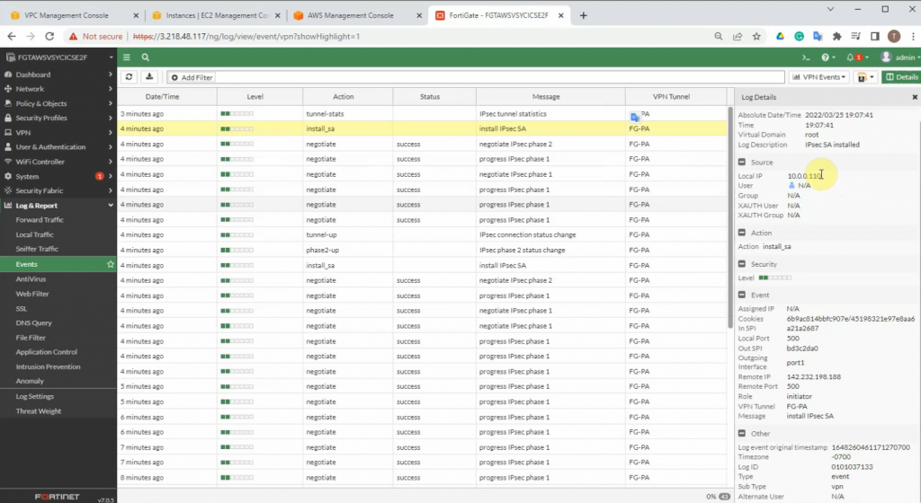
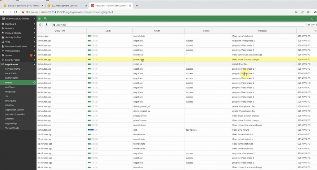
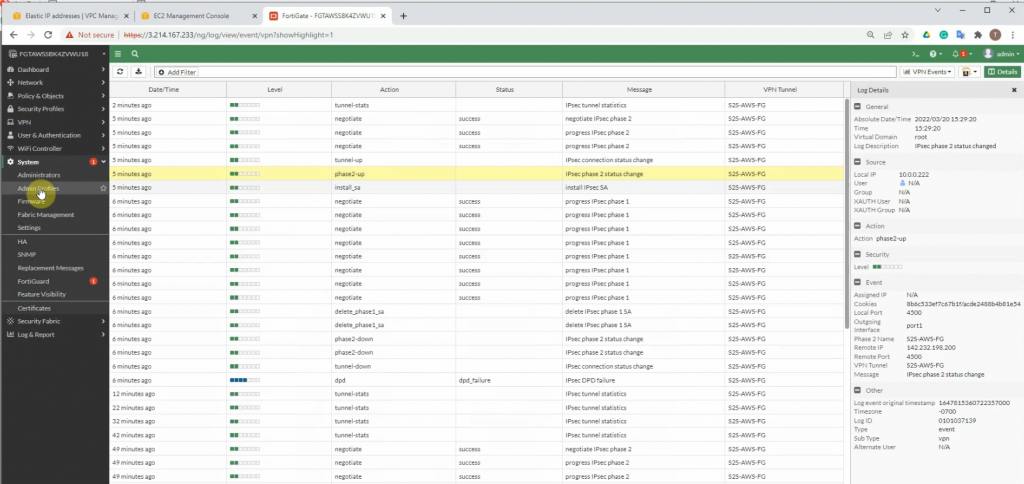
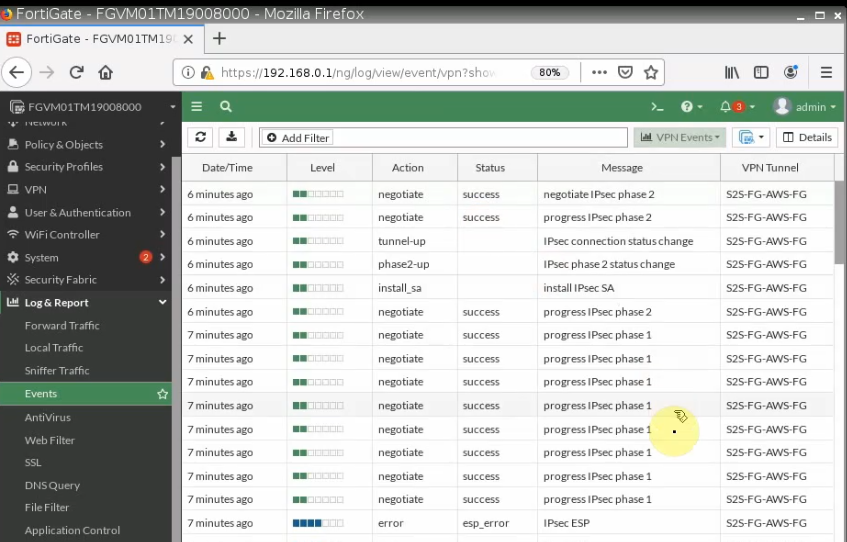
Click on the log and Report to see events that are related to VPN.
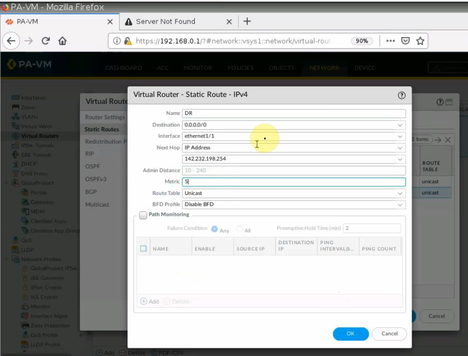
+ Back to PA to create another static route to allow the PA LAN subnet to access the Internet.
A next hop is the default gateway of the PA public subnet.
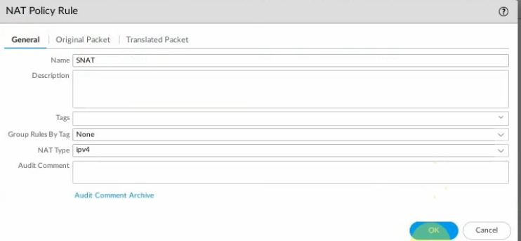
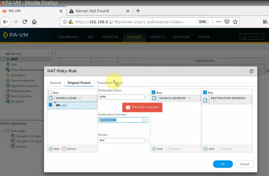
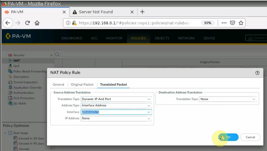
Create a SNAT policy to allow traffic from the PA LAN subnet to the Internet.
On the Destination interface, should choose e1/1. This is because VPN site-to-site traffic does not use NAT.
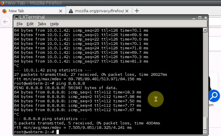
Ping 8.8.8.8 from PA LAN subnet.
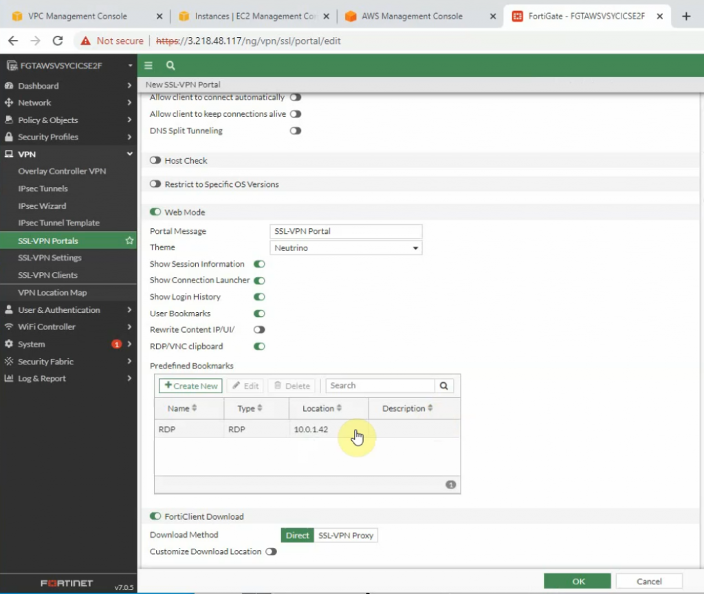
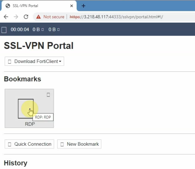
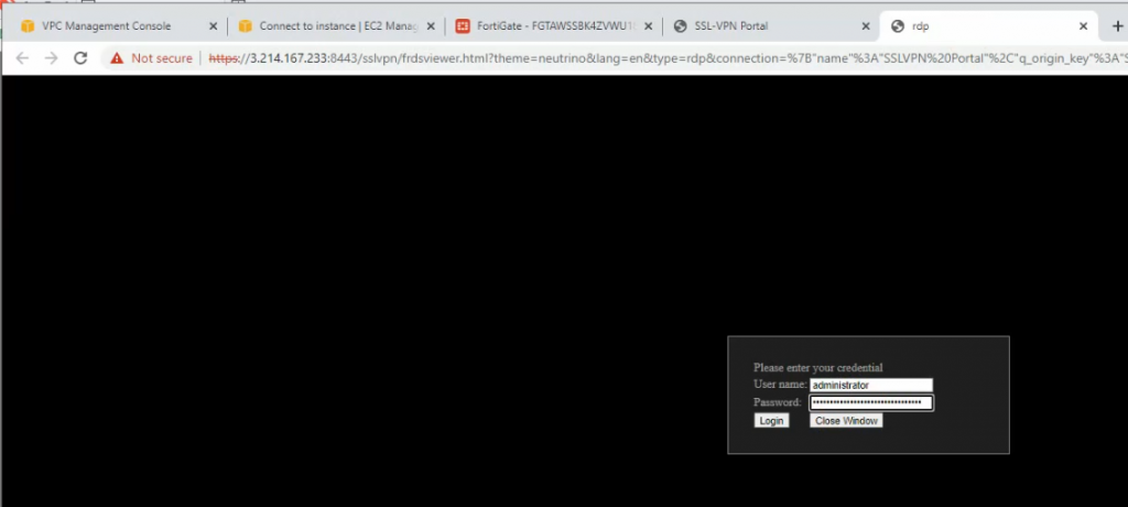
+ Create an SSLVPN portal on FortiGate to allow to access FG private subnet on the SSLVPN zone.
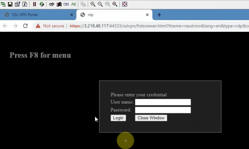
RDP to Windows 2016 instance private subnet on AWS is 10.0.1.42
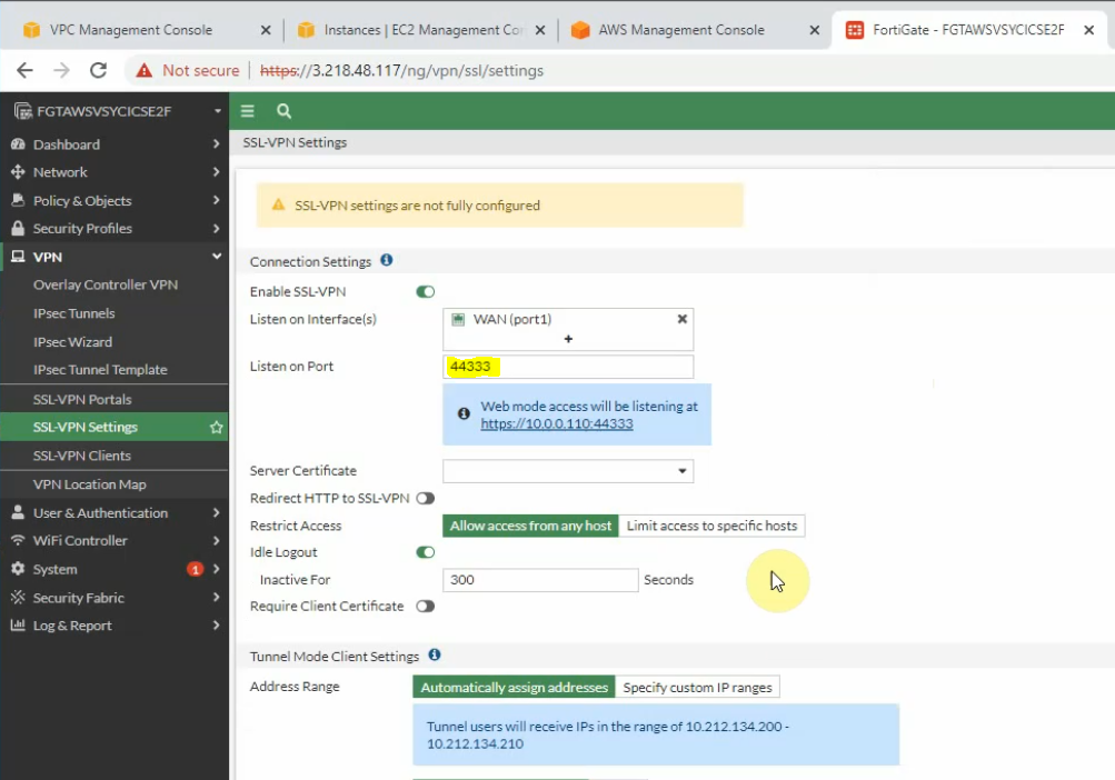
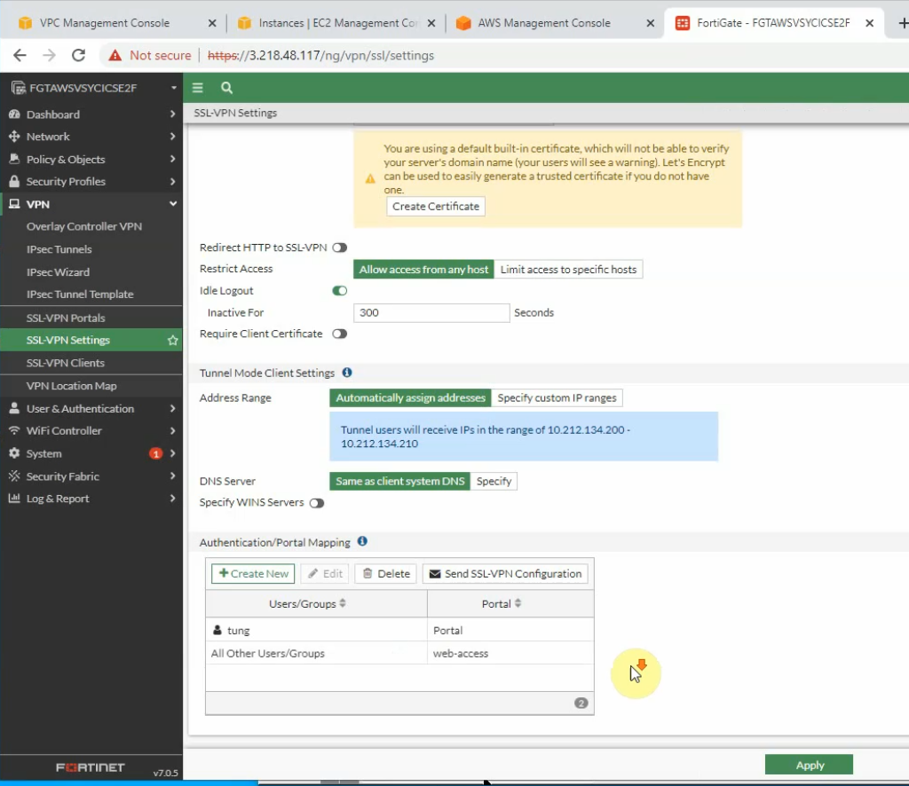
On SSLVPN setting, enable SSLVPN via 44333 port.
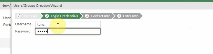
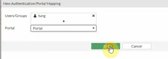
Create a new username and password to access SSLVPN.
Then assign this user to the portal that we have created on previous step.
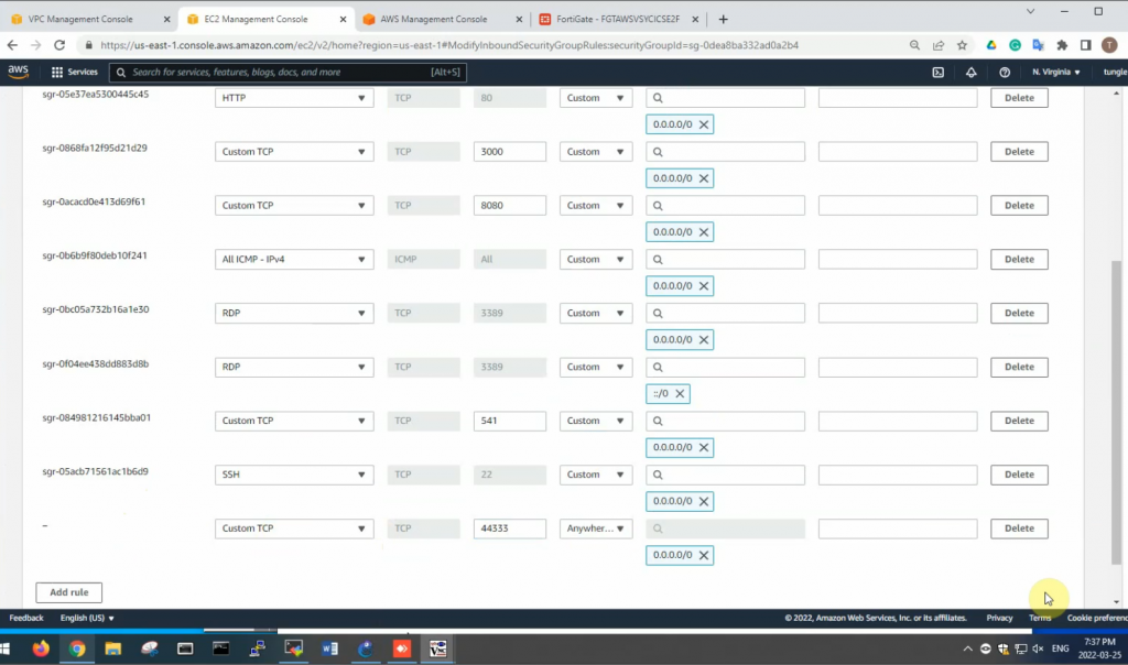
Edit the Security Group to allow Internet traffic to SSLVPN port is 44333.
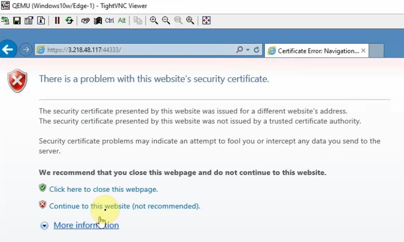
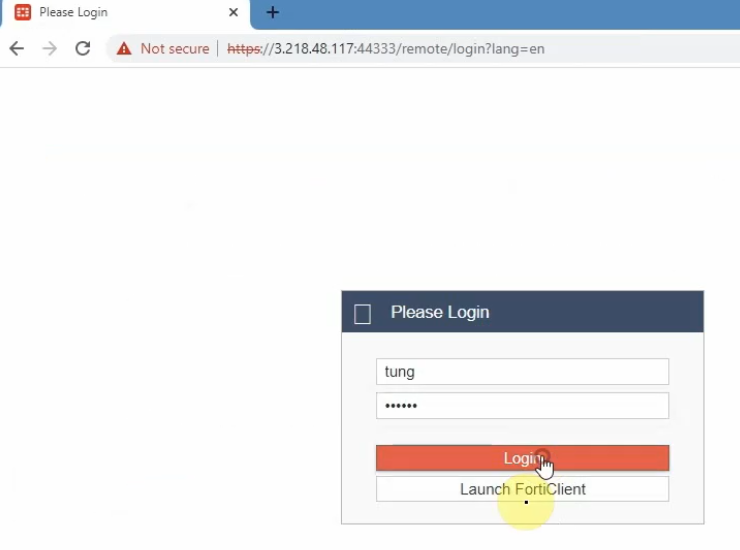
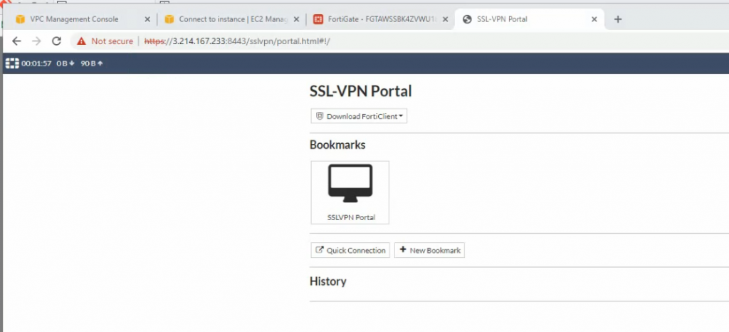
From a Windows machine, access SSLVPN portal on FG.
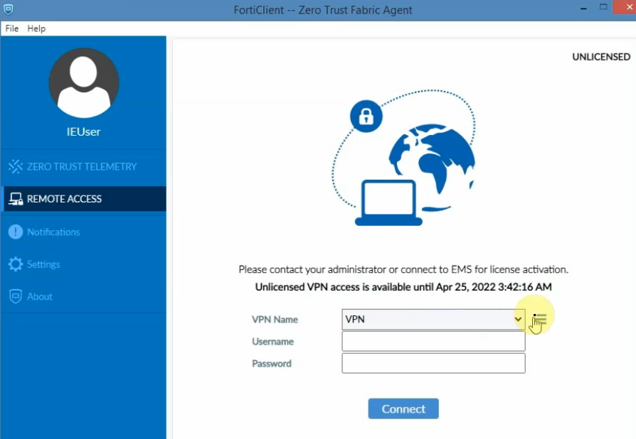
Also, we can use Forticlient to access if we have a license.
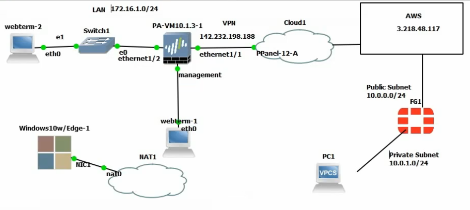
This is a topology that is used to deploy this lab.
+ Configure FortiGate on AWS.
Create a new VPC with a CIDR network is 10.0.0.0/16. Then, create both Lab Public subnet and :ab Private subnet on AWS.
Create a new Internet gateway and attach to your VPC.
Create route tables.
Add a new route to the public Route table.
Associate the public subnet to the Public Route table.
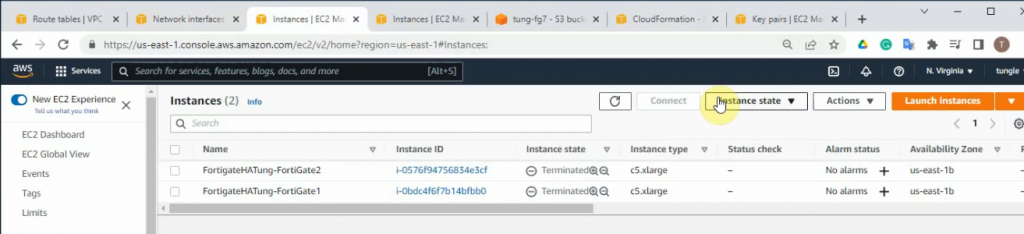
Go to EC2 and create a new FortiGate instance.
Create a new private interface for FortiGate.
Attach the interface to FortiGate.
Disable “Source and destination check” on both Public and Private FortiGate interfaces.
Create a new Elastic IP address and assign it to your FortiGate instance.
Assign the Elastic IP address to public FortiGate interface.
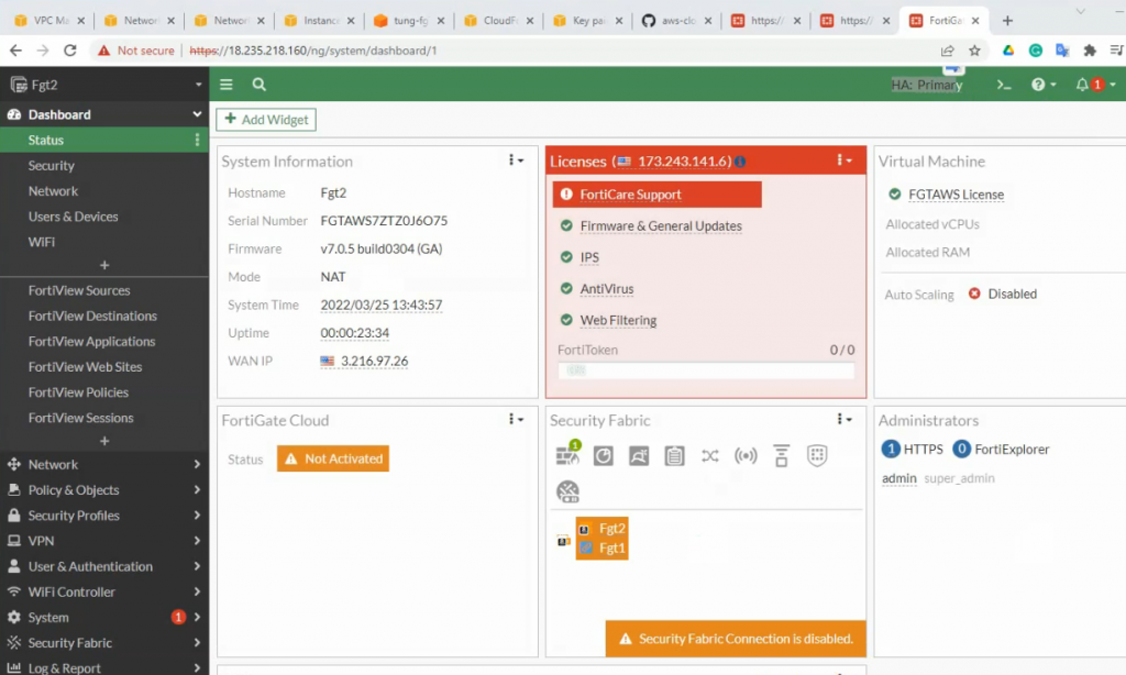
Access FortiGate management interface.
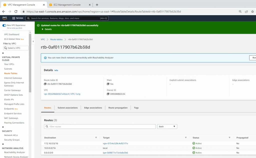
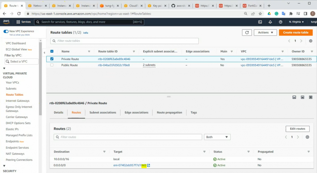
Add a new route on a Private Route table to the Private FortiGate interface.
Create a new Windows instance on AWS.
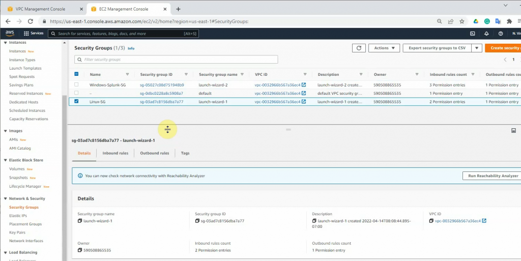
Security Group.
Modify Windows Security Group to allow ICMP traffic.
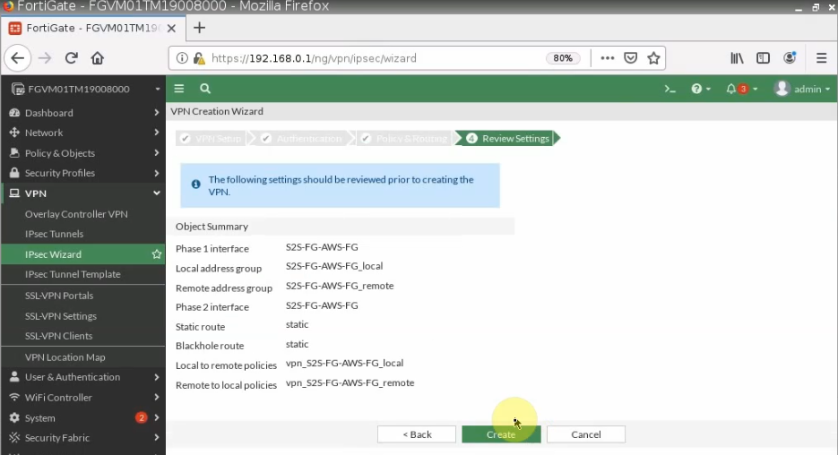
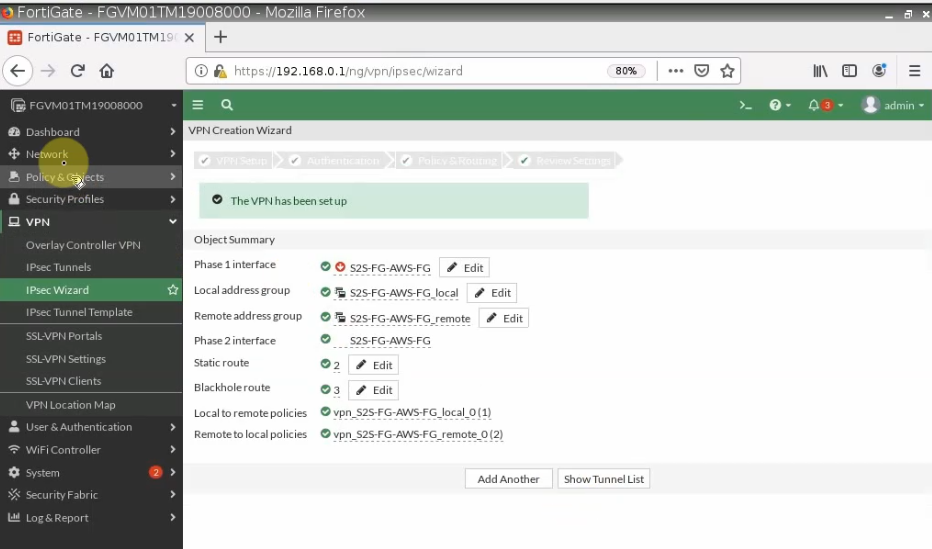
Configure VPN site to site.
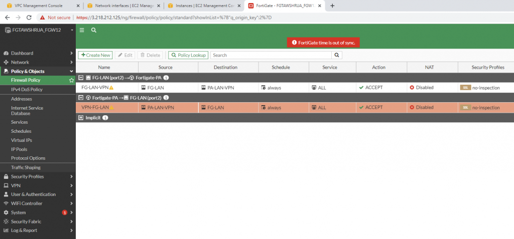
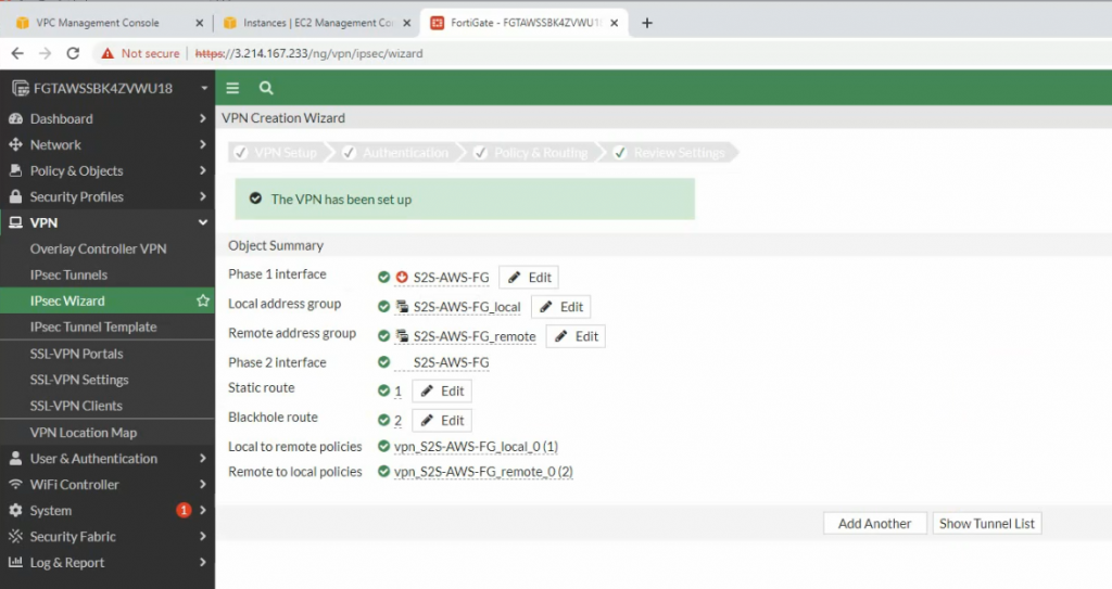
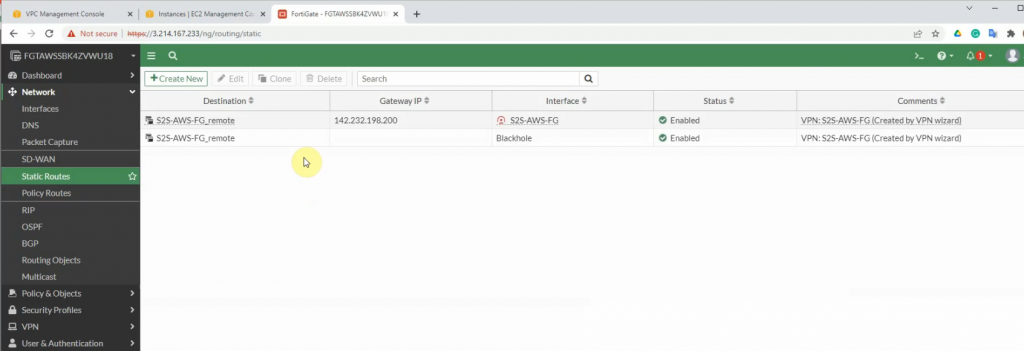
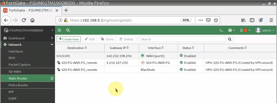
There are two routes that have been automatically created on FortiGate on the static routes setting.
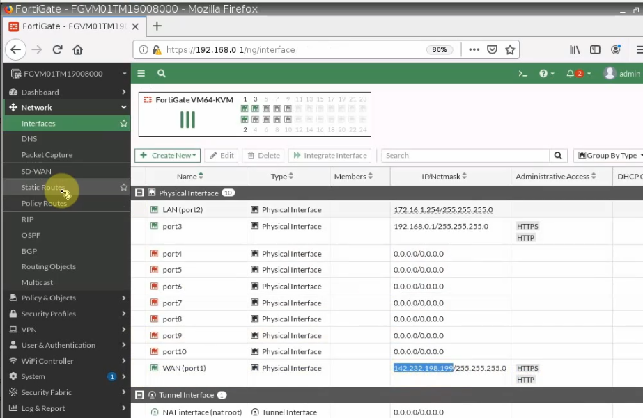
+ Configure FortiGate on-prem.
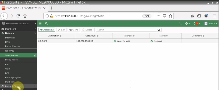
Configure a default route on FortiGate.
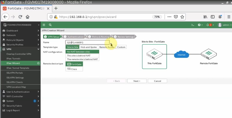
Configure VPN site to site between both FortiGate.
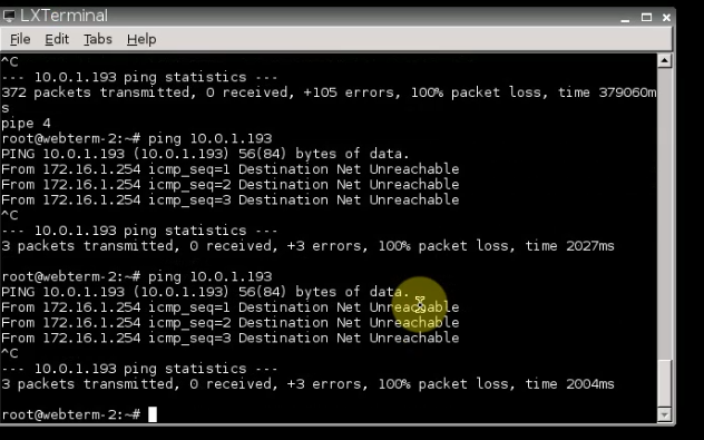
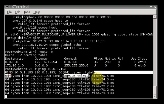
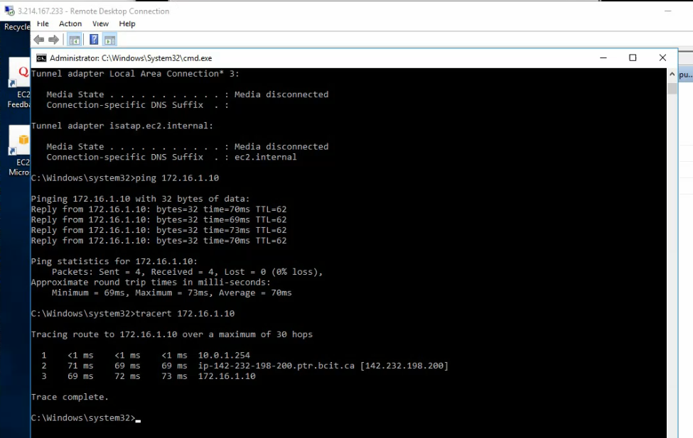
+ Pings a Windows instance on AWS from a machine on FortiGate on-prem. Remember to access RDP to the machine and disable Windows Firewall to allow ICMP traffic from on-prem to that machine.
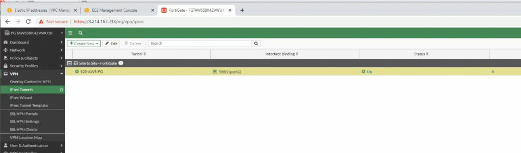
The IPSEC tunnel is up.
Pings from Windows instance on AWS to a computer on FortiGate LAN subnet on-prem.