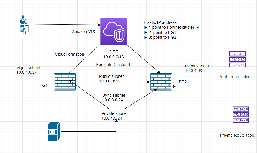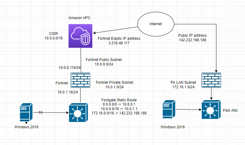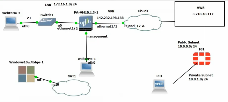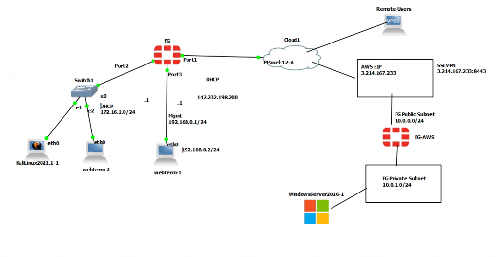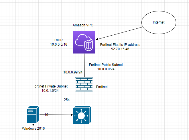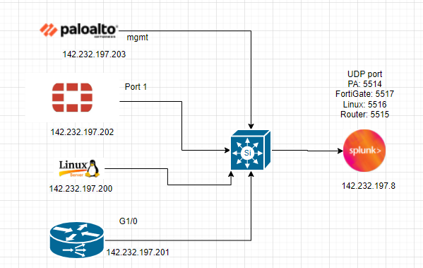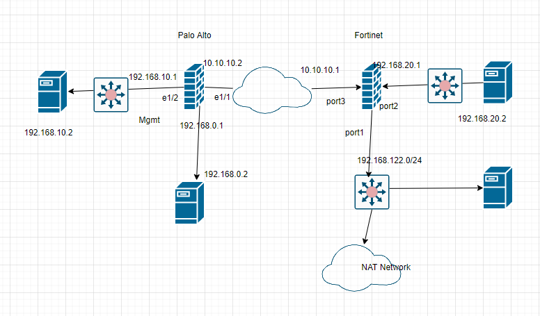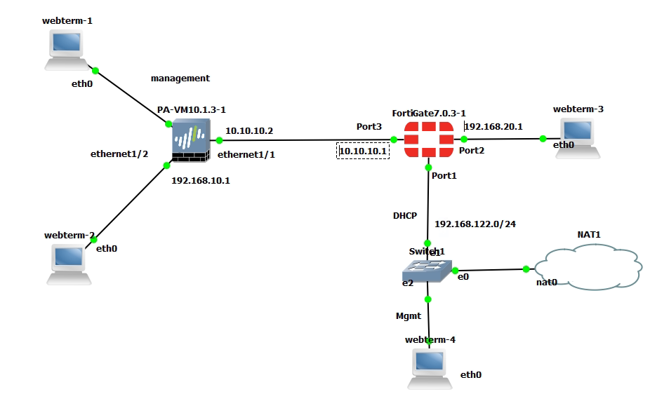
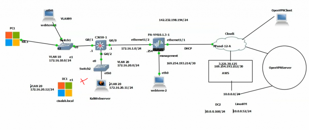
This is the diagram is used to deploy this lab.
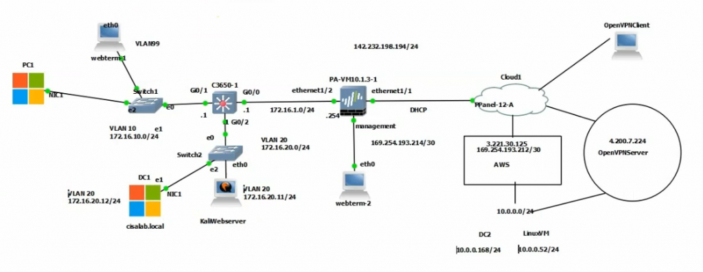
In this lab.
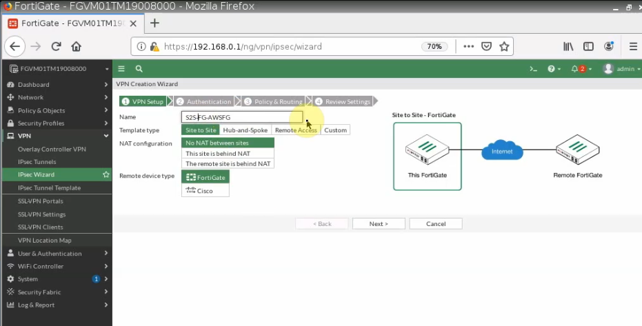
- Configure VPN site to site IKEv2 between Palo Alto and Virtual Private Gateway on AWS.
- Implementing multi-master domain controllers on-prem and AWS.
- Authenticating OpenVPN tunnel via LDAP to support people working from home to access corporate servers on AWS.
- Disconnect the domain controller on-prem to simulate migrating corporate servers to AWS in the near future.
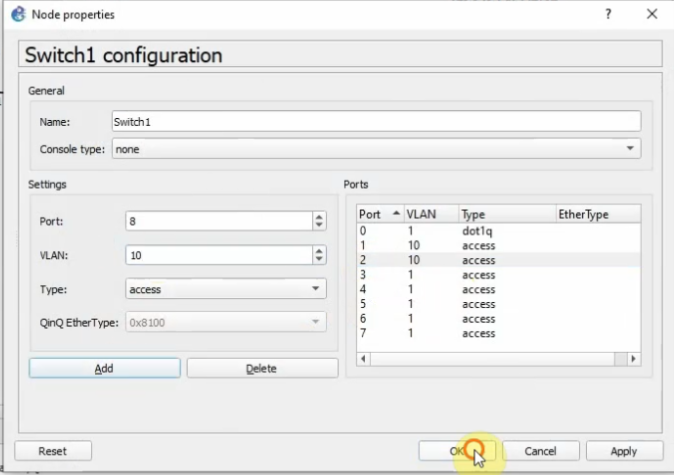
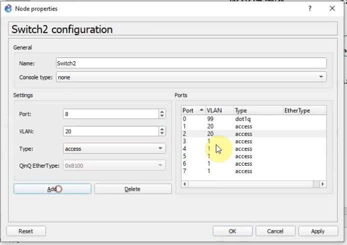
Core Switch configuration.
CoreSW
conf t
hostname CoreSW
ip routing
ip dhcp excluded-address 172.16.10.1 172.16.10.10
!
ip dhcp pool VLAN10
network 172.16.10.0 255.255.255.0
default-router 172.16.10.1
dns-server 172.16.20.12
interface GigabitEthernet0/0
no switchport
ip address 172.16.1.1 255.255.255.0
!
interface GigabitEthernet0/1
switchport trunk allowed vlan 10,20,99
switchport trunk encapsulation dot1q
switchport trunk native vlan 99
switchport mode trunk
negotiation auto
!
interface GigabitEthernet0/2
switchport trunk allowed vlan 10,20,99
switchport trunk encapsulation dot1q
switchport trunk native vlan 99
switchport mode trunk
interface Vlan10
ip address 172.16.10.1 255.255.255.0
!
interface Vlan20
ip address 172.16.20.1 255.255.255.0
!
router ospf 1
router-id 1.1.1.1
network 172.16.0.0 0.0.255.255 area 0
!
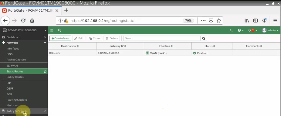
ip route 0.0.0.0 0.0.0.0 172.16.1.254
---
SWCore#sh vlan brief
VLAN Name Status Ports
---- -------------------------------- --------- -------------------------------
1 default active Gi0/3, Gi1/0, Gi1/1, Gi1/2
Gi1/3, Gi2/0, Gi2/1, Gi2/2
Gi2/3, Gi3/0, Gi3/1, Gi3/2
Gi3/3
10 End users active
20 Servers active
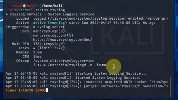
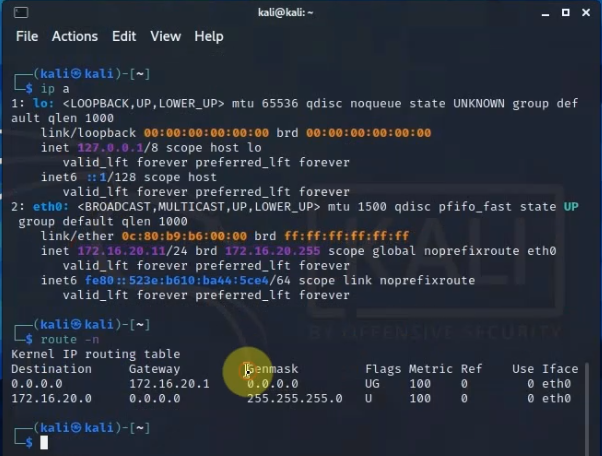
99 Native VLAN activeCheck Kali VM., start SSH and Apache service on this machine.
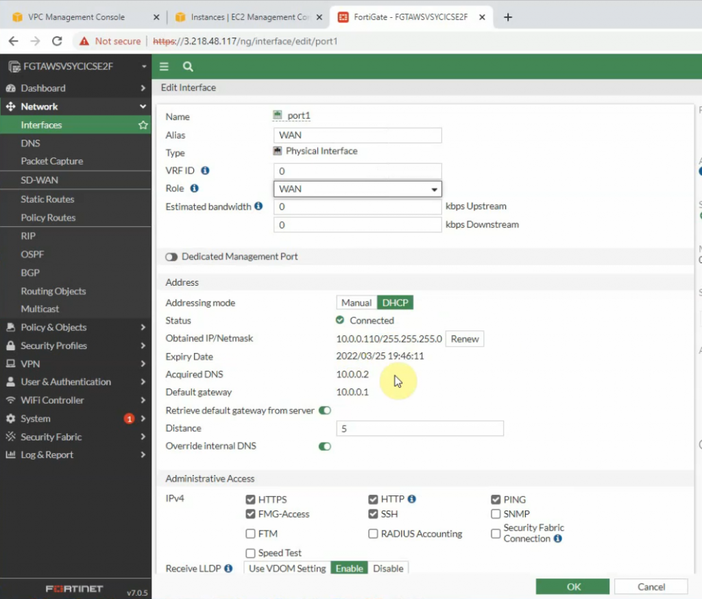
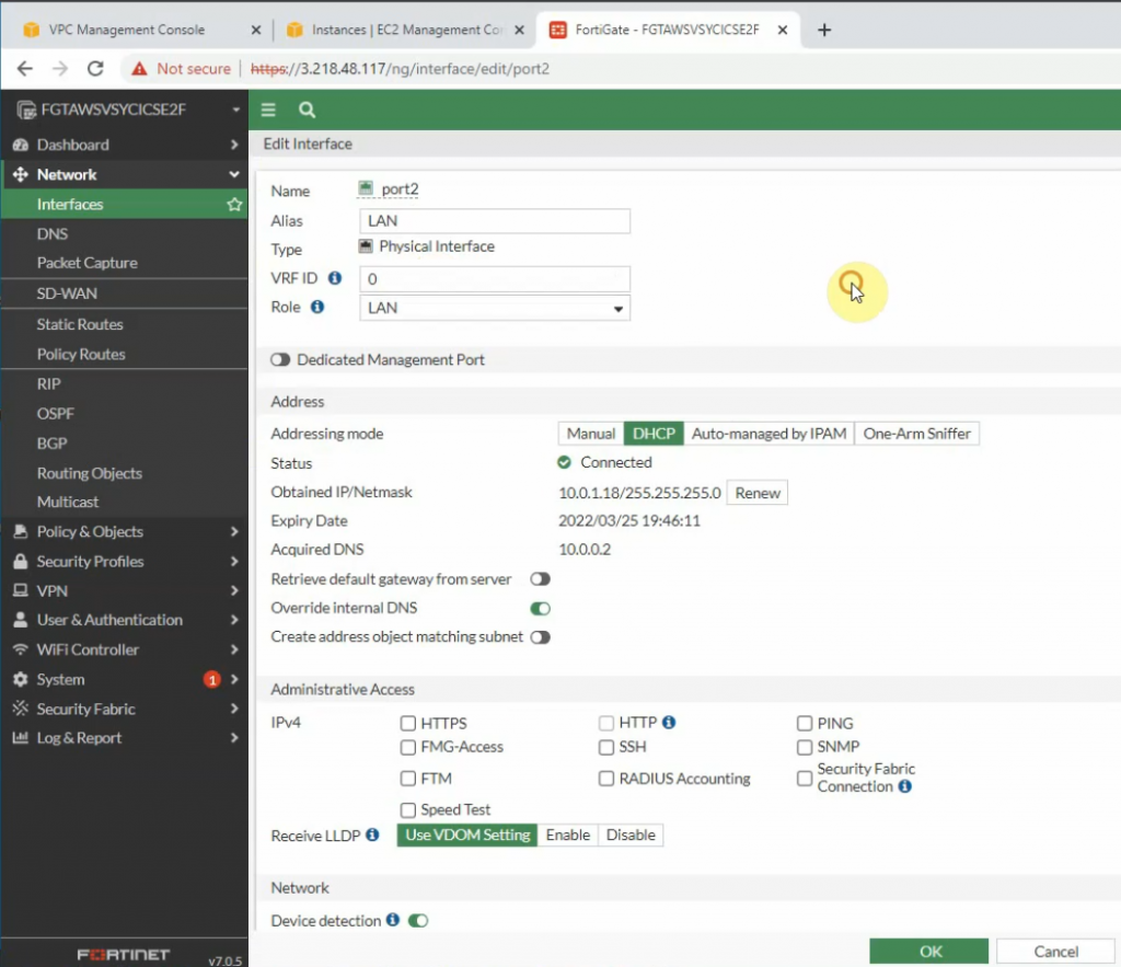
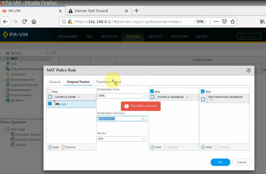
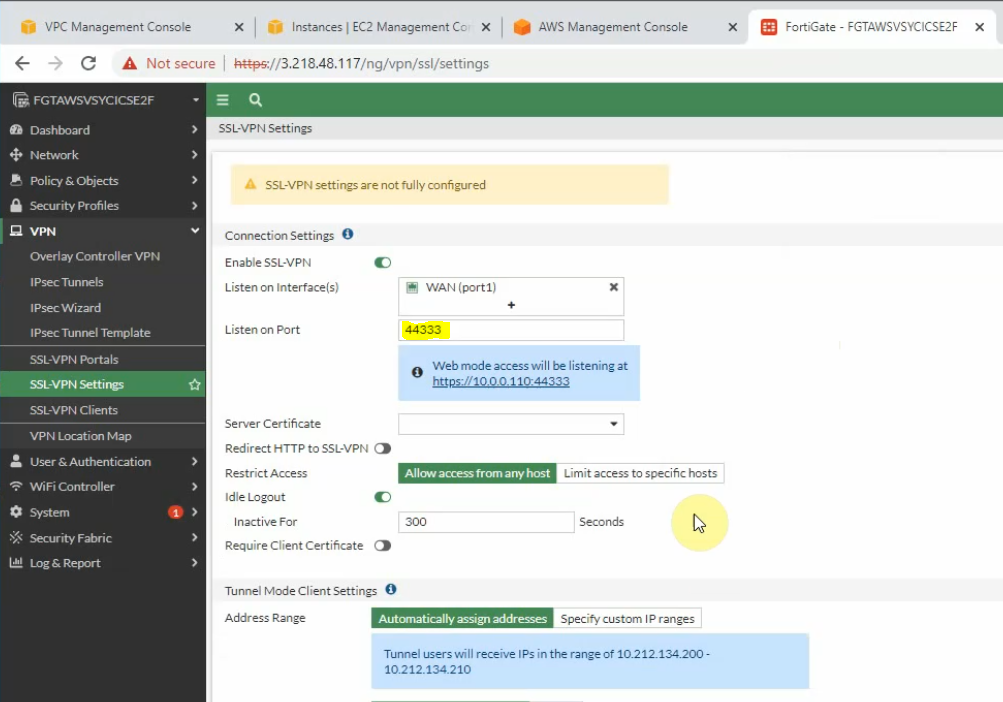
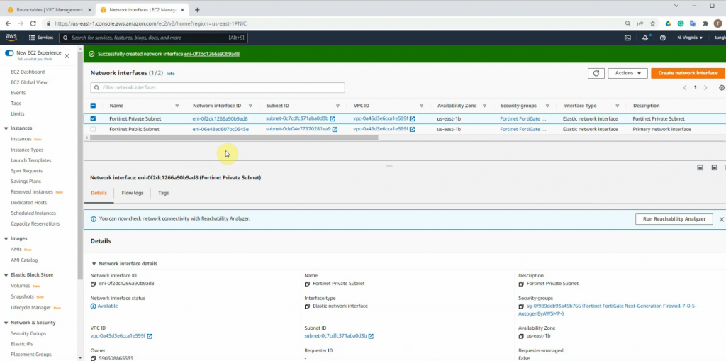
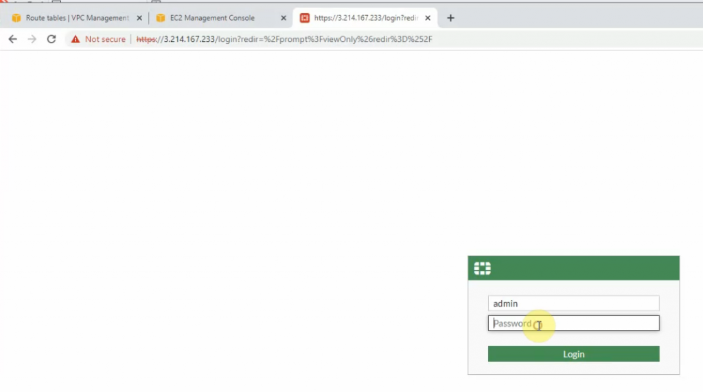
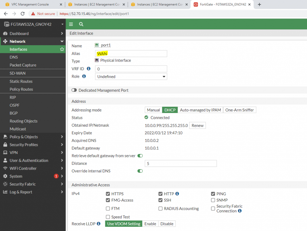
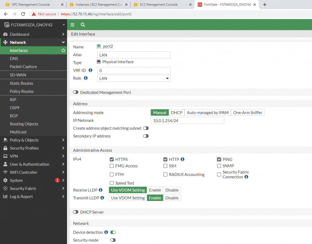
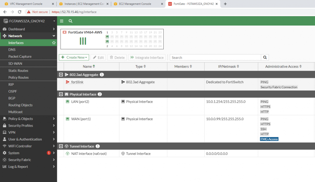
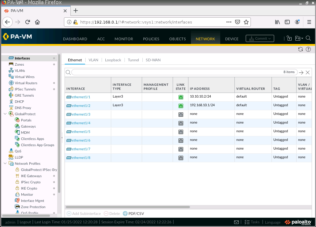
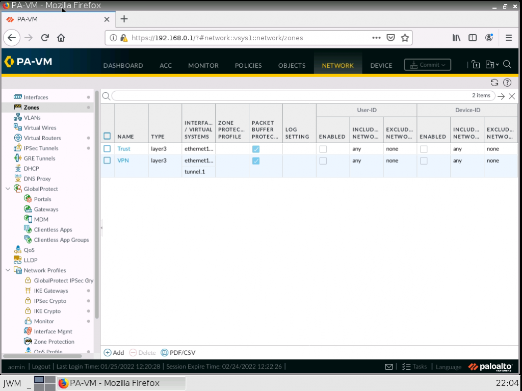
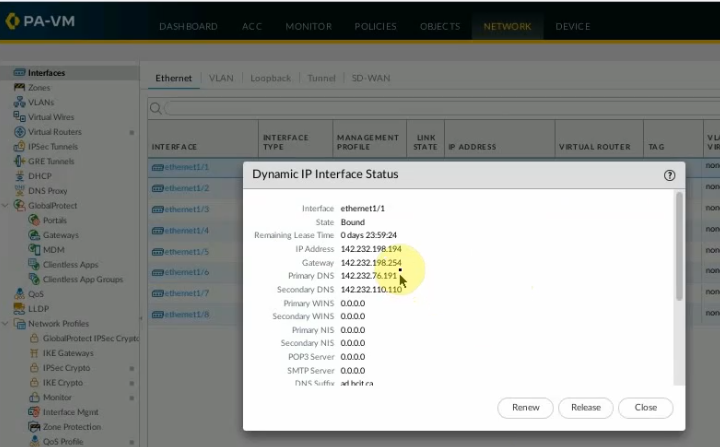
On Palo Alto.
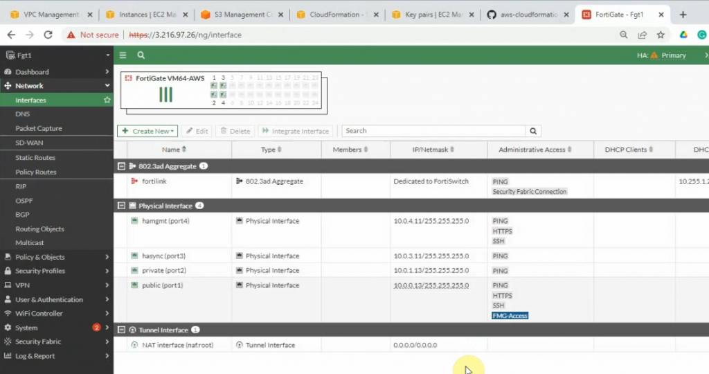
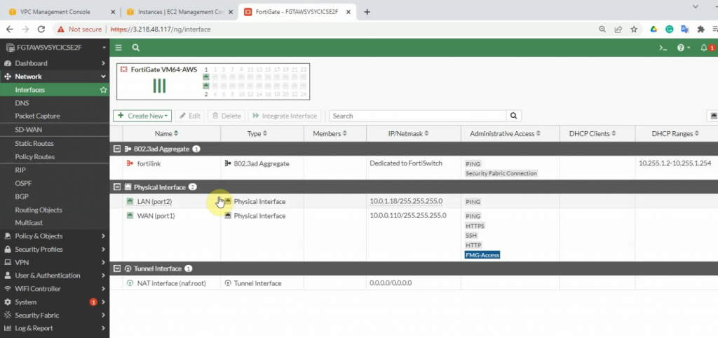
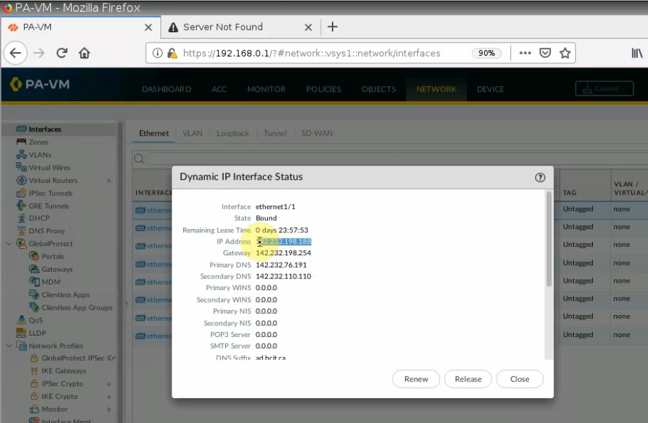
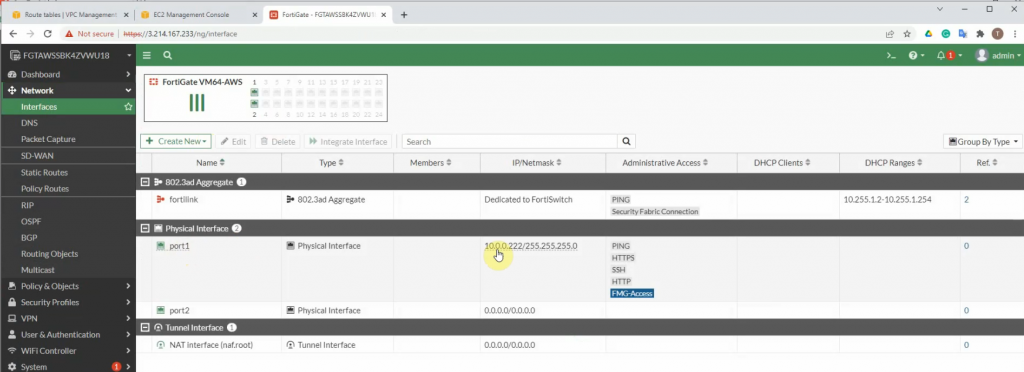
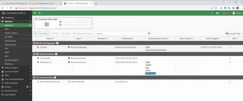
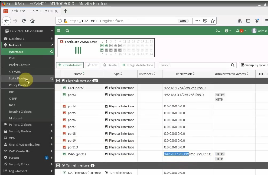
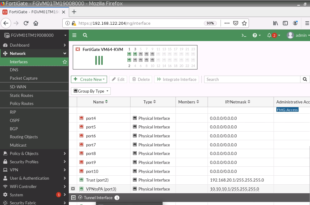
LAN interface.
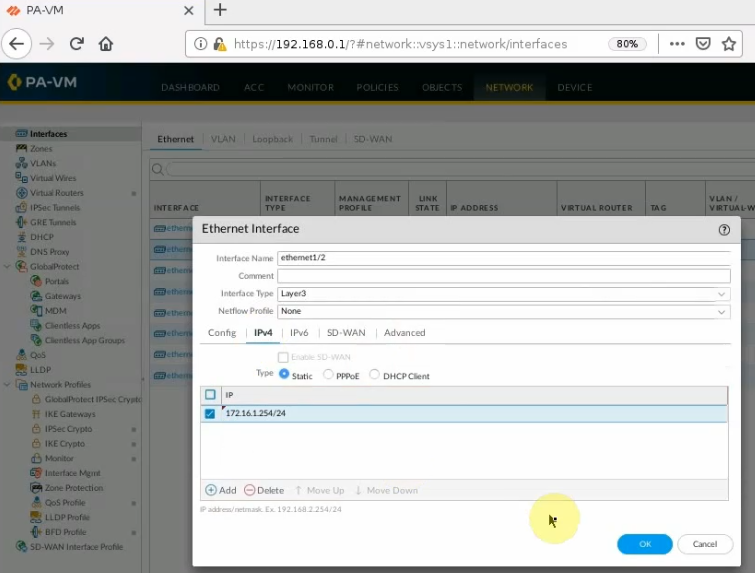
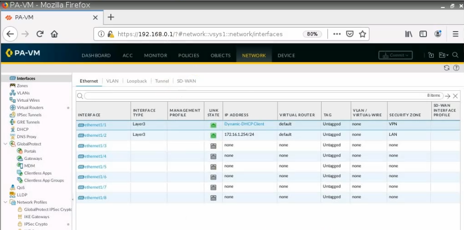
e1/1 belongs to the VPN zone, and e1/2 belongs to the LAN zone, respectively.
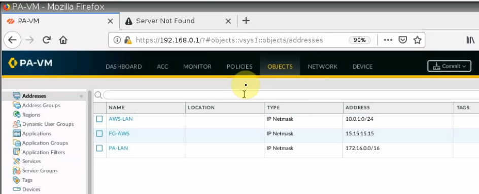
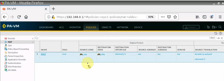
Create a new network object for the PA LAN subnet.
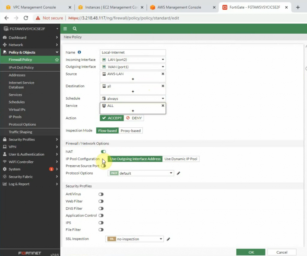
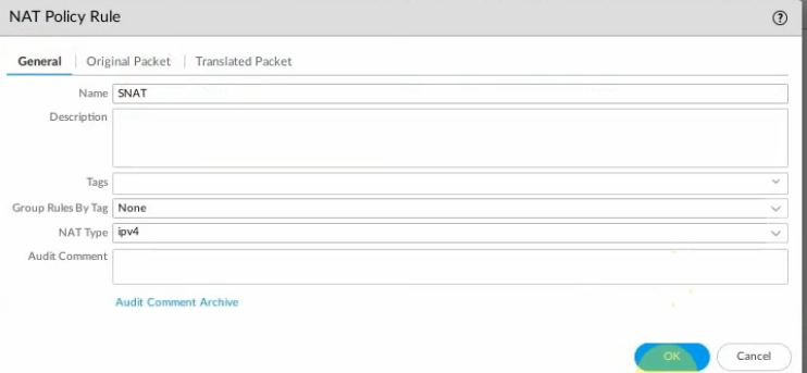
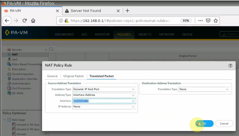
Configure SNAT to allow traffic from the PA LAN subnet to access the Internet.
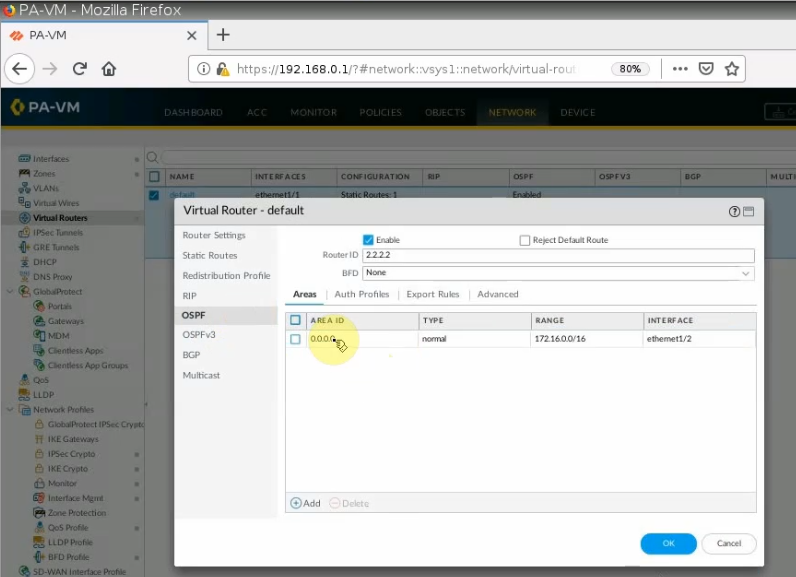
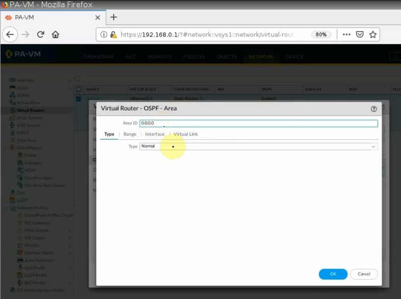
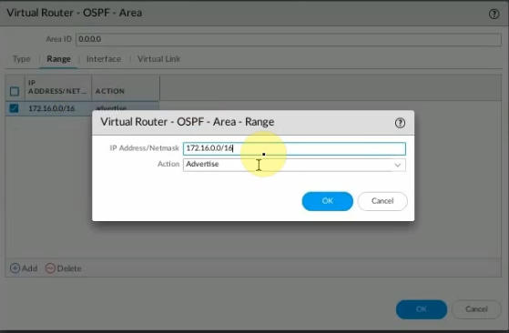
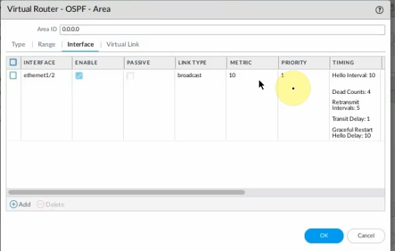
Configure OSPF on PA.
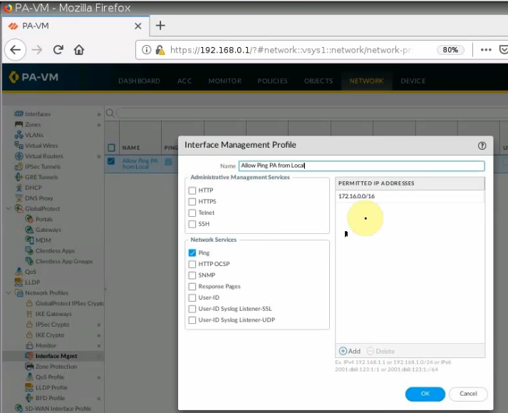
Allow ICMP on the Mgmt interface to troubleshoot.
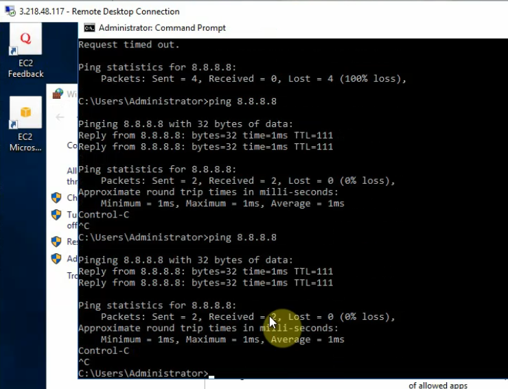
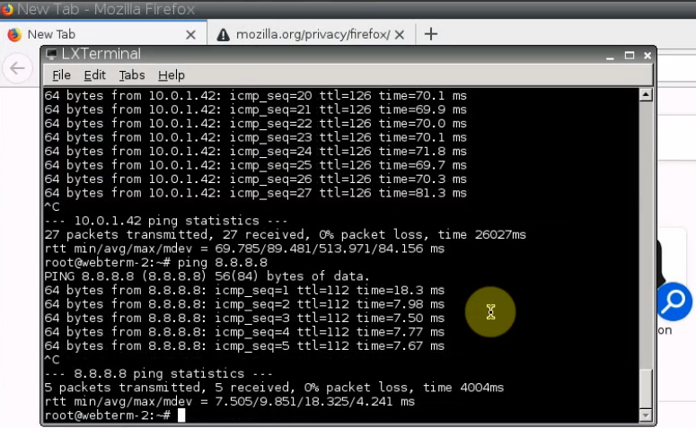
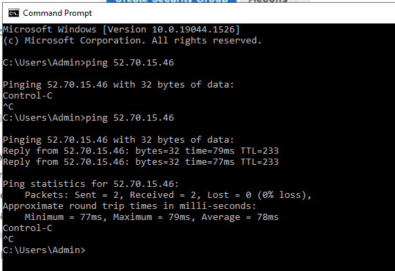
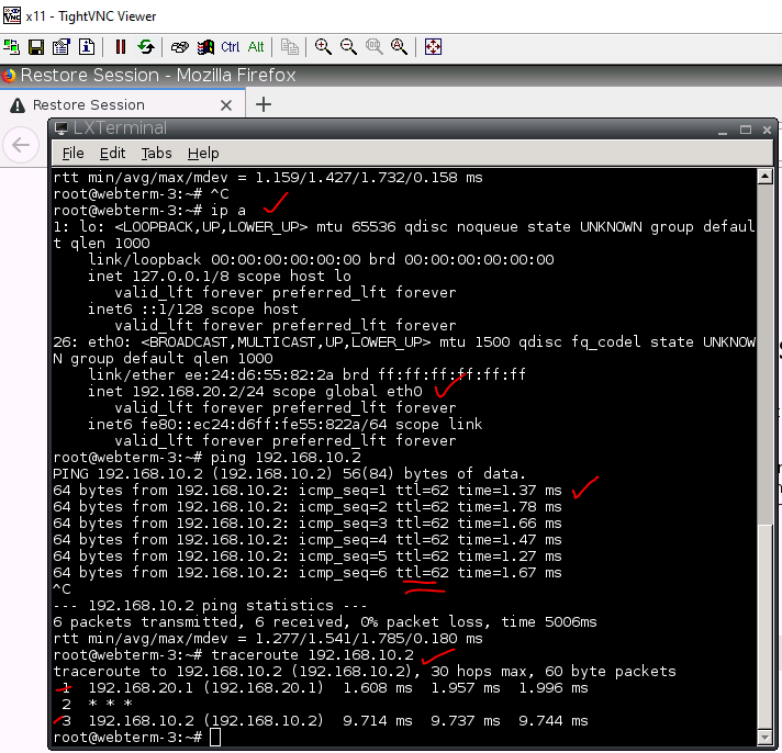
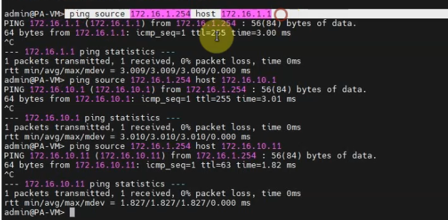
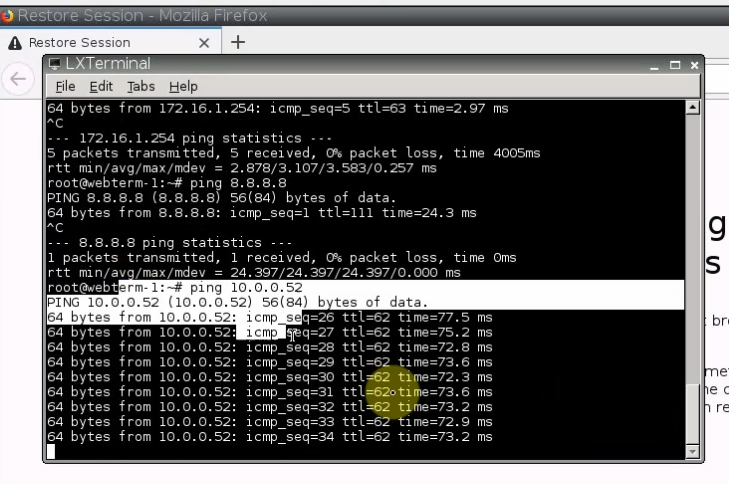
Ping from PA.
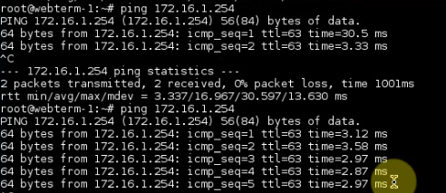
Ping from a VM on the PA LAN subnet.
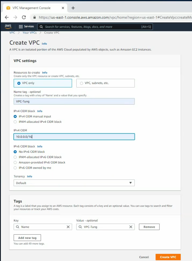
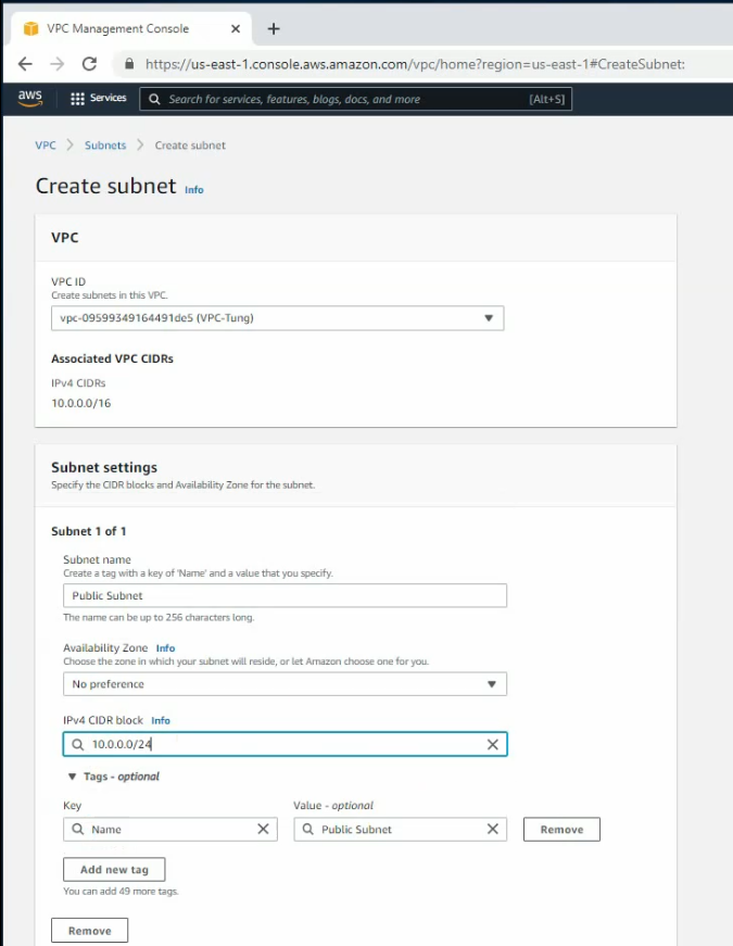
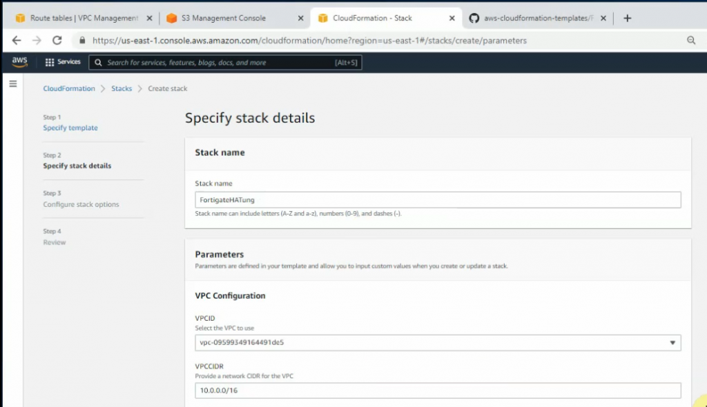
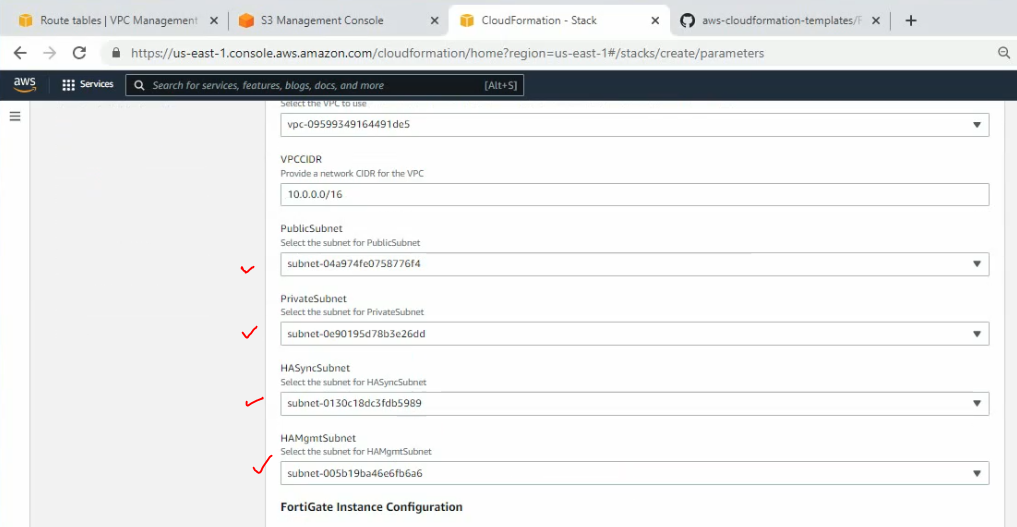
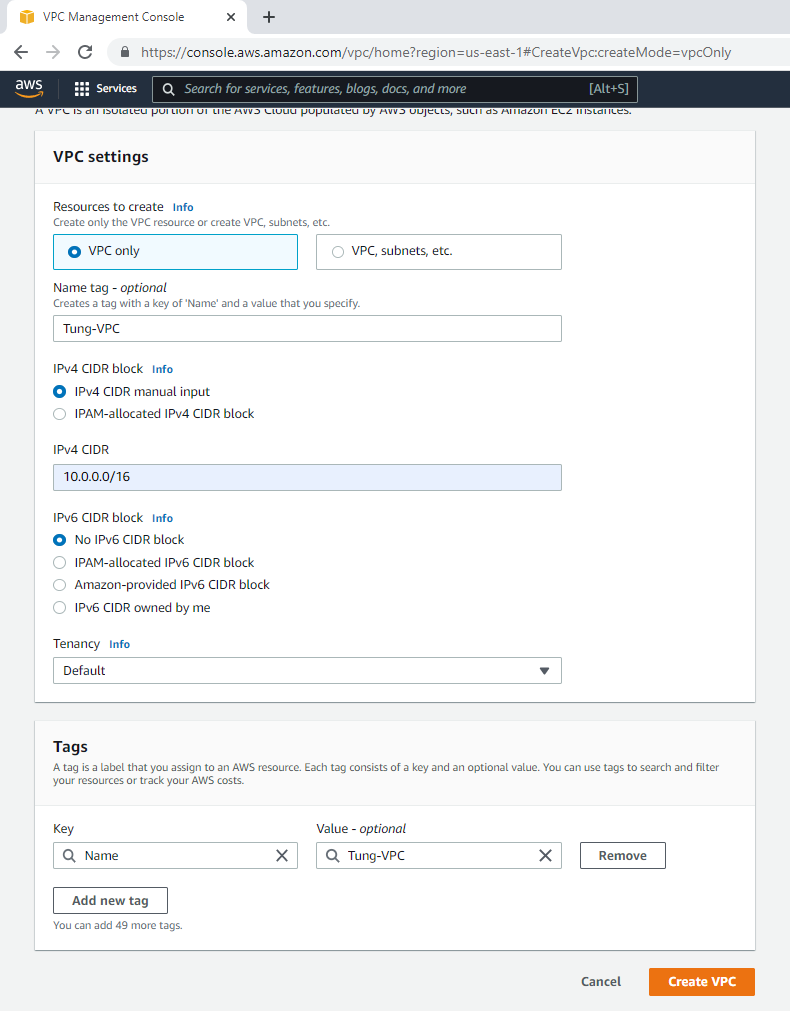
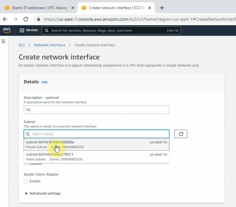
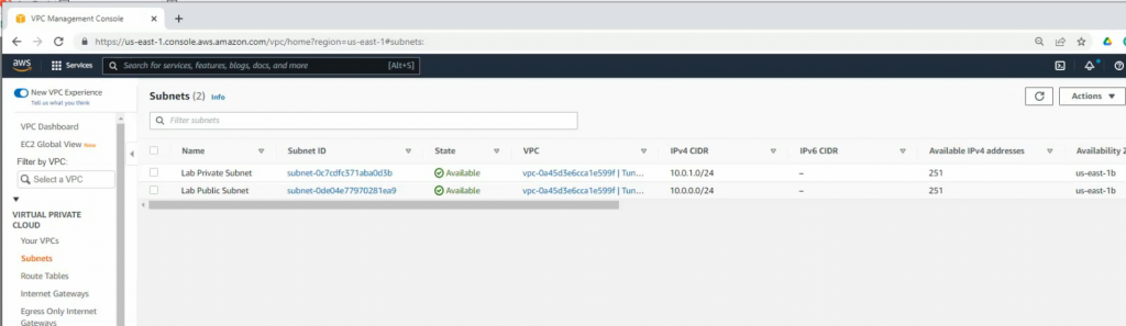
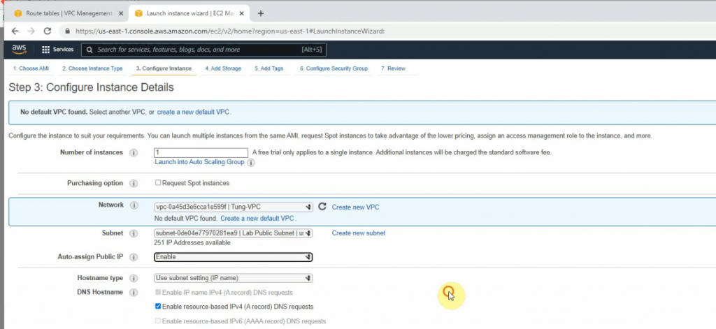
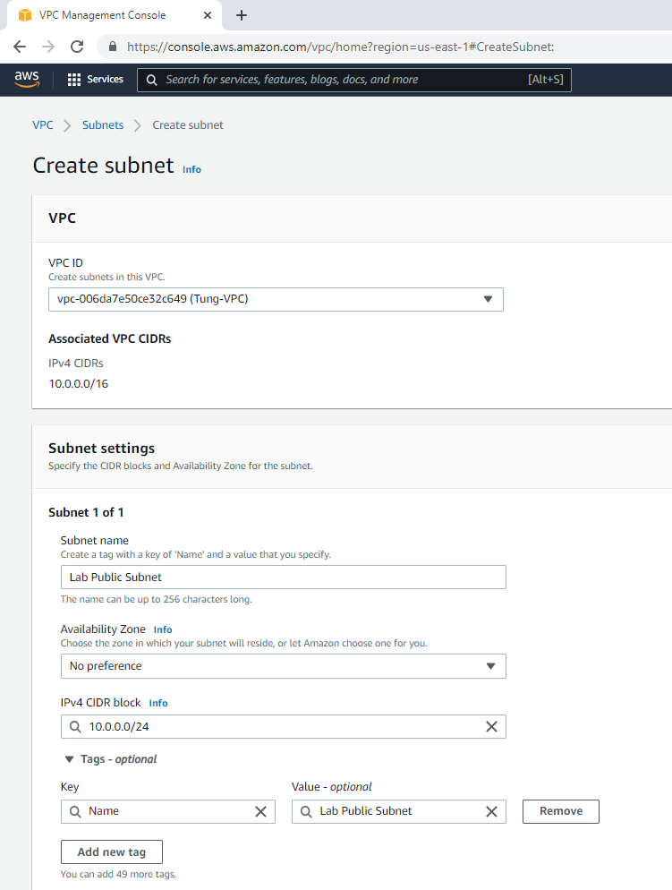
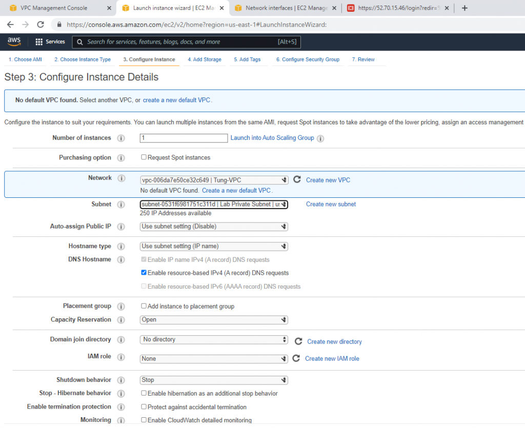
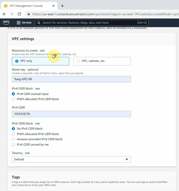
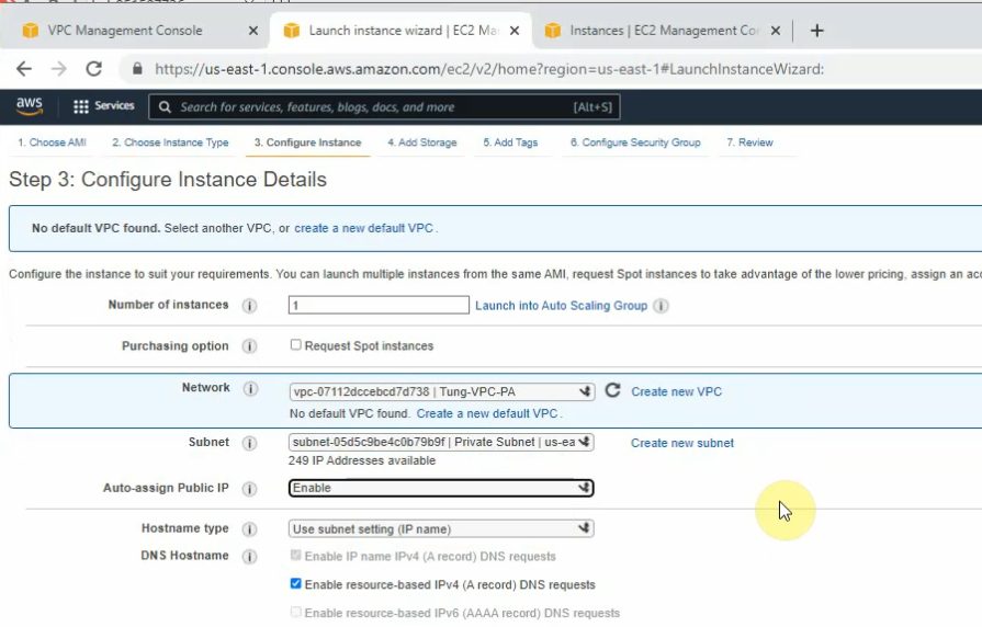
+ Create a new VPC.
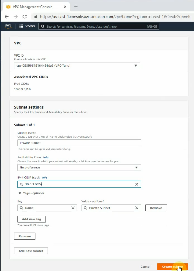
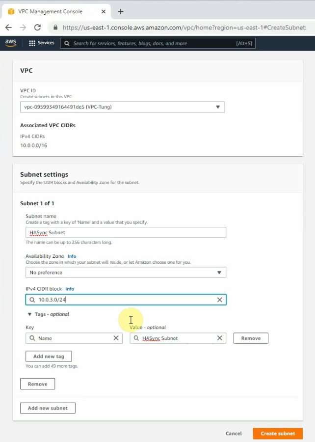
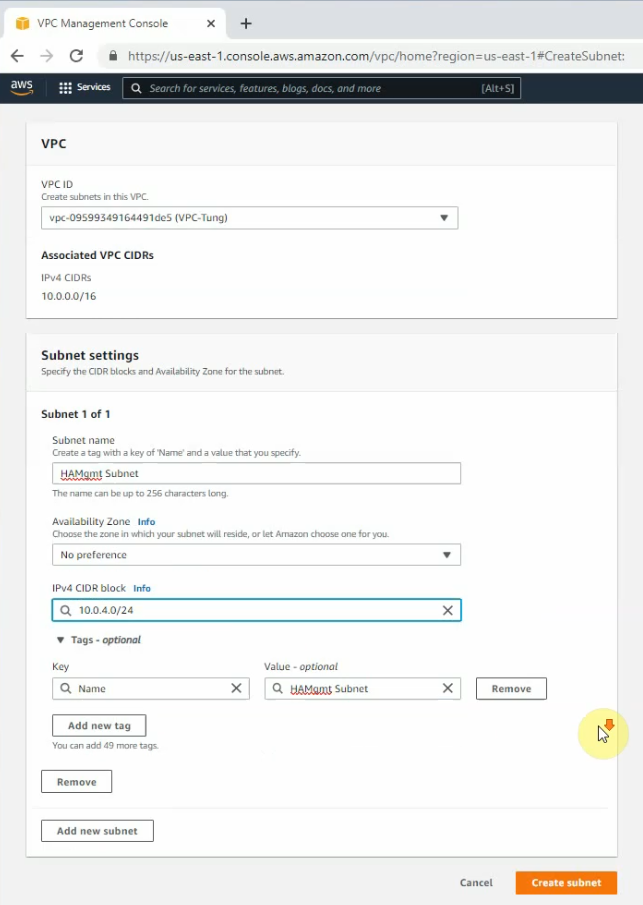
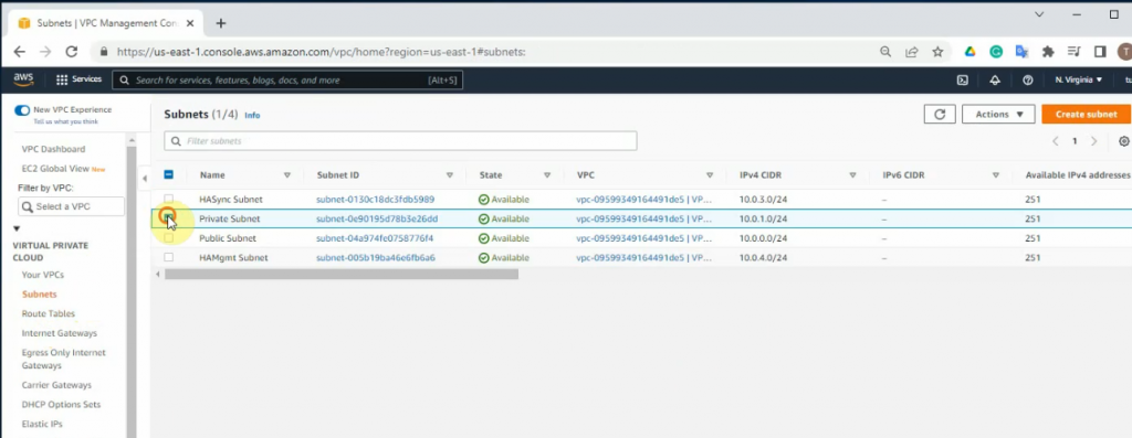
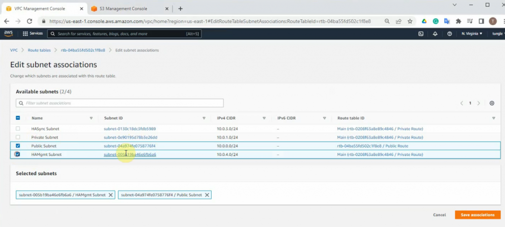
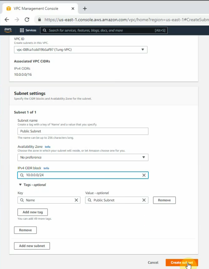
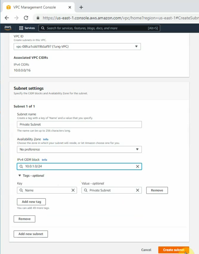
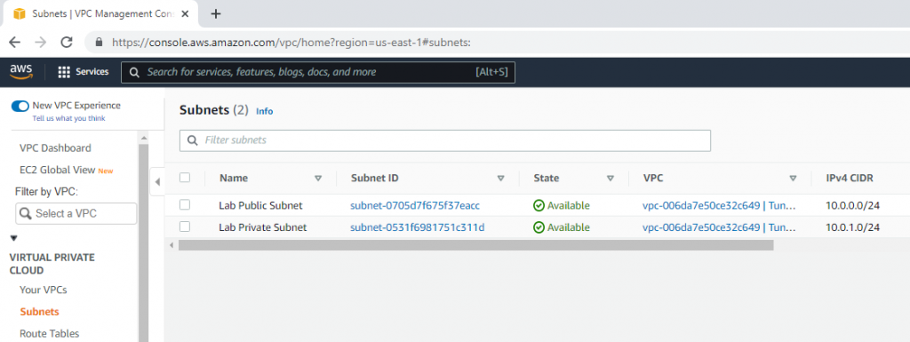
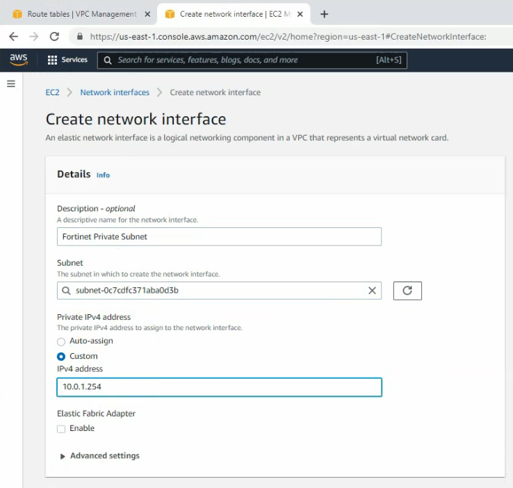
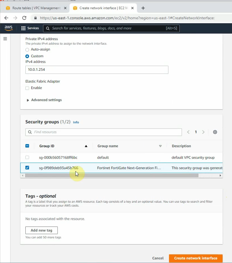
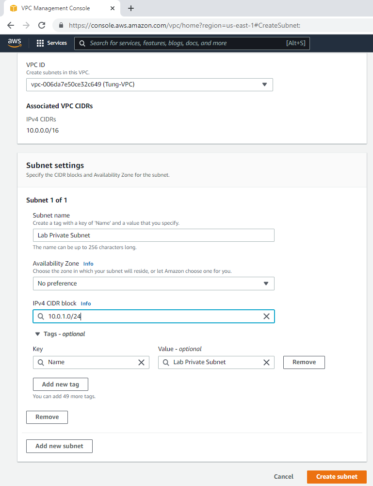
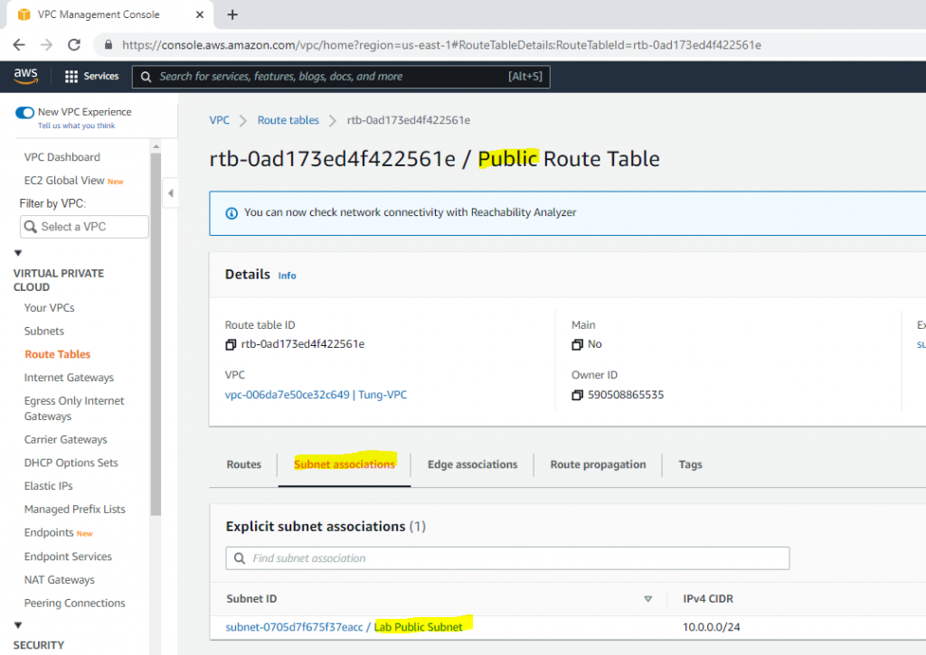
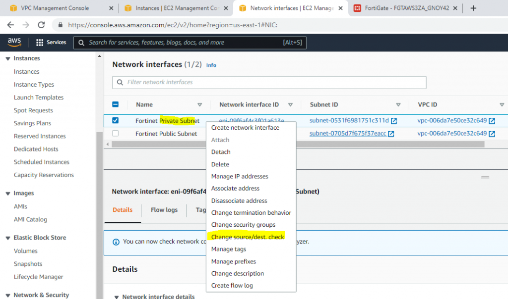
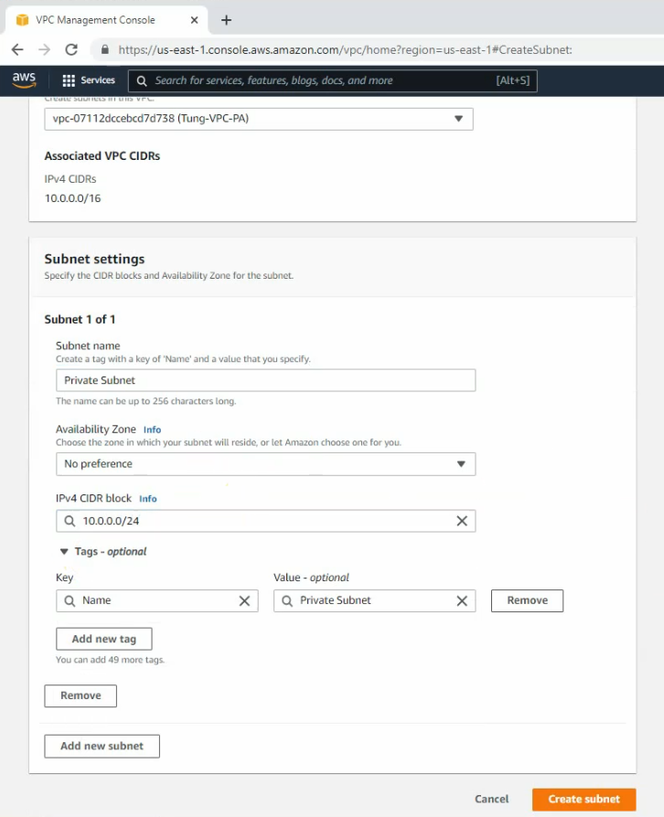
Create a private subnet.
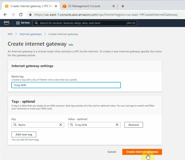
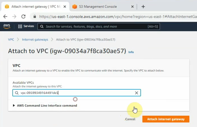
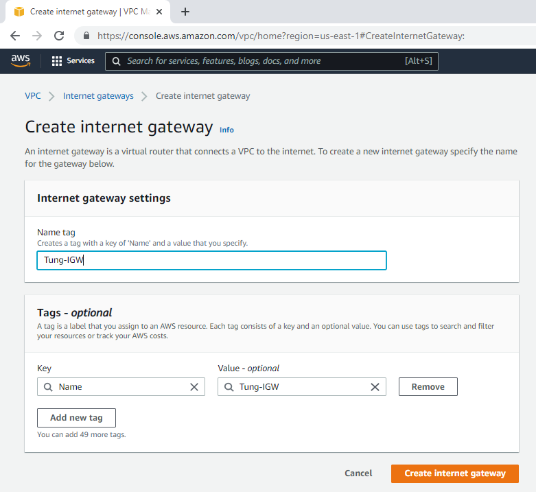
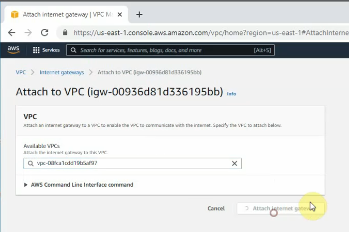
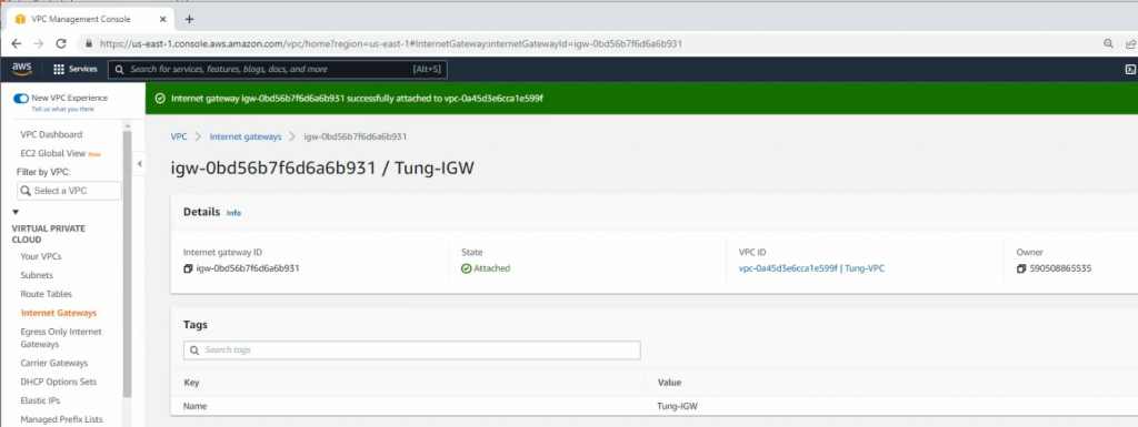
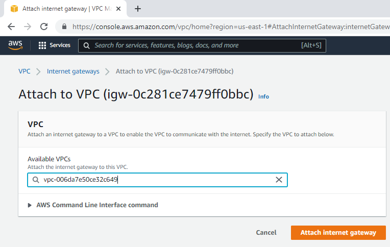
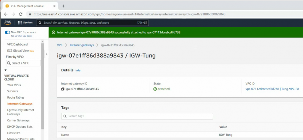
Create and attach Internet gateway to your VPC.
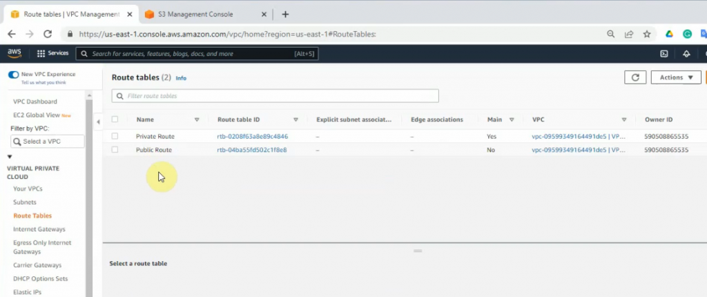
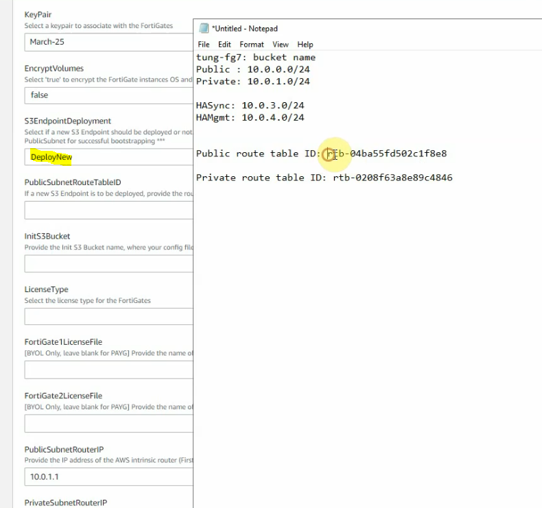
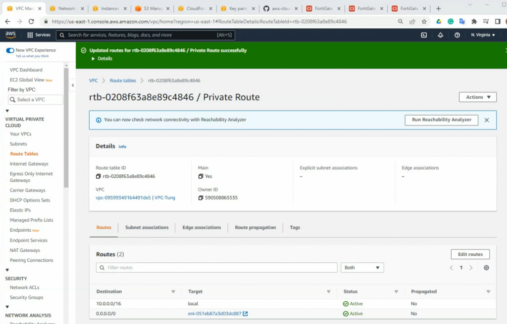
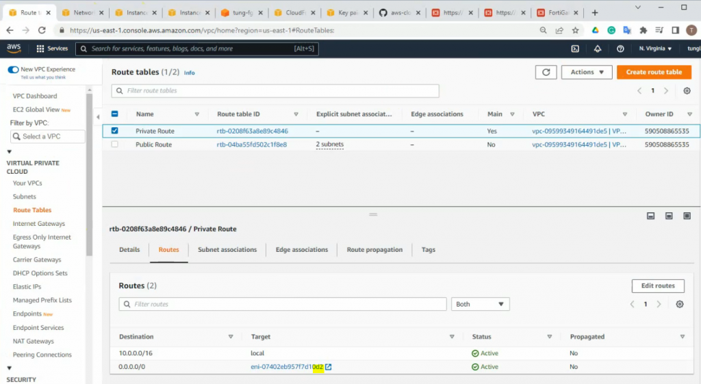
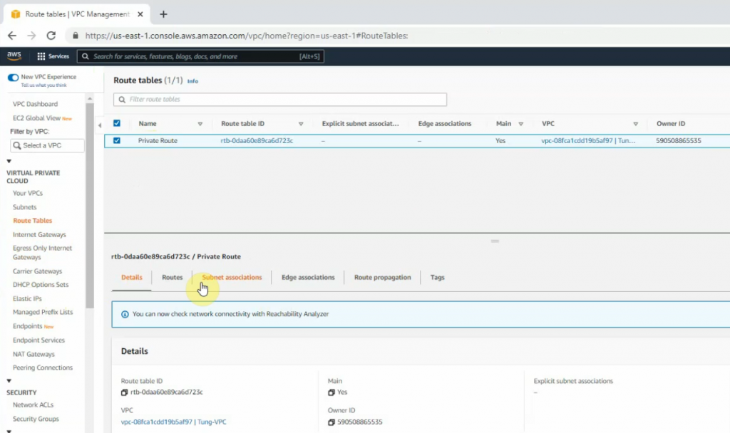
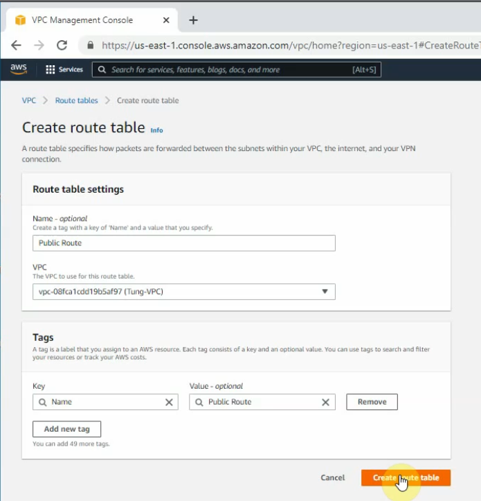
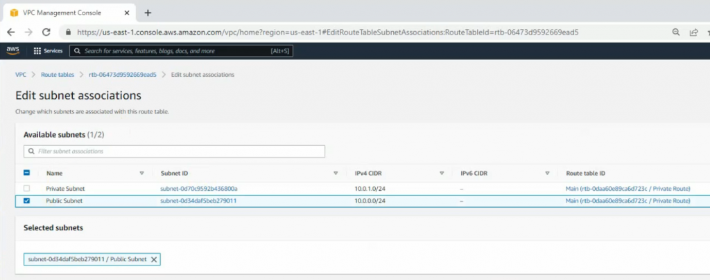
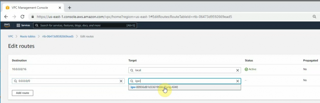
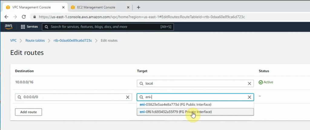
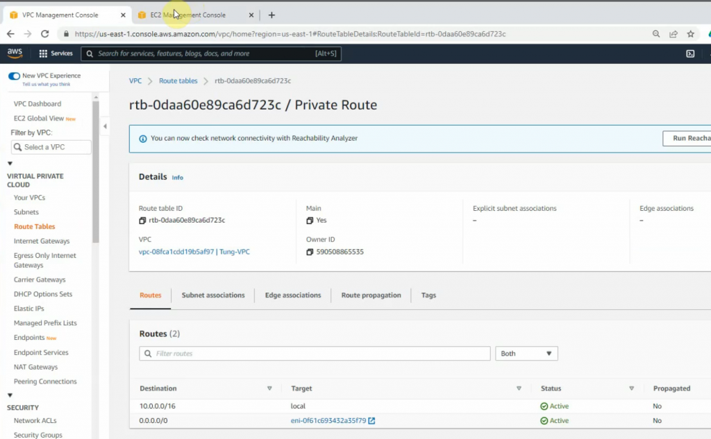
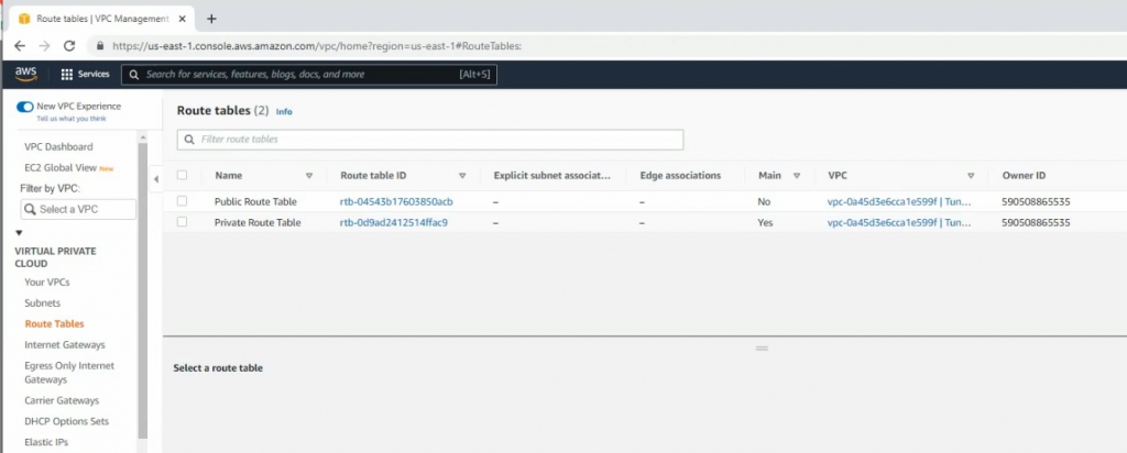
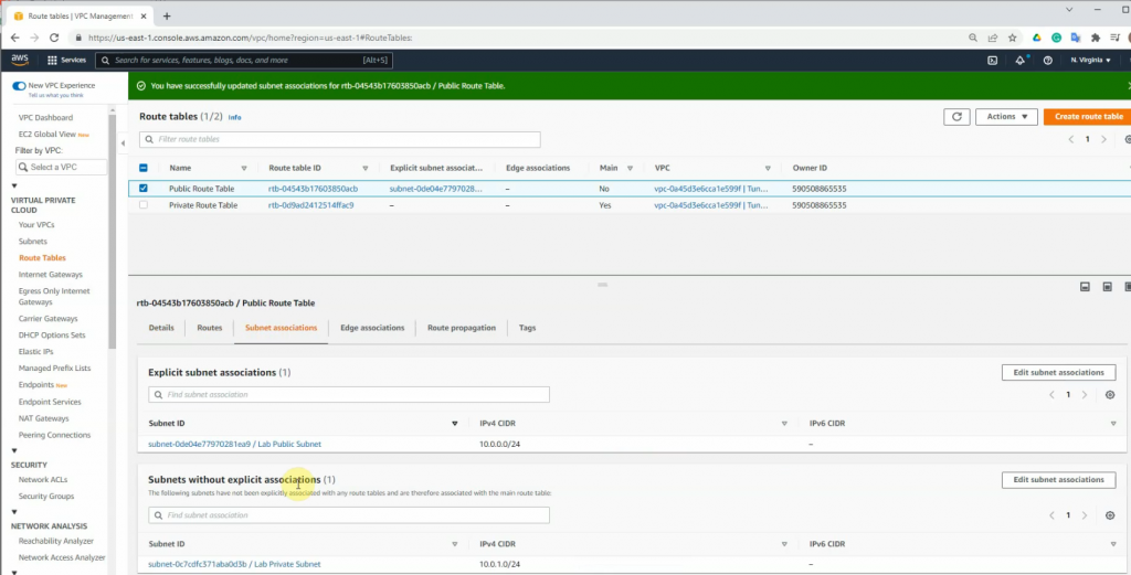
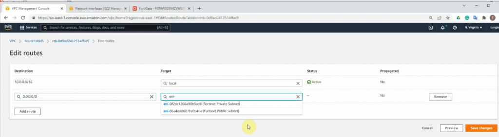
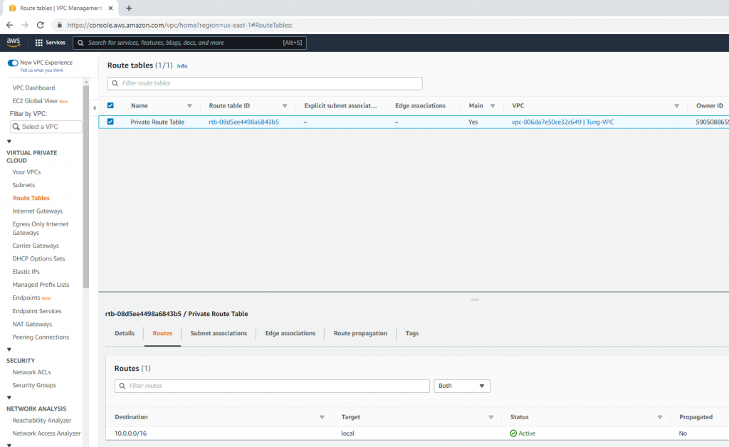
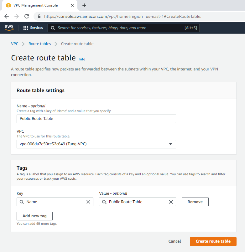
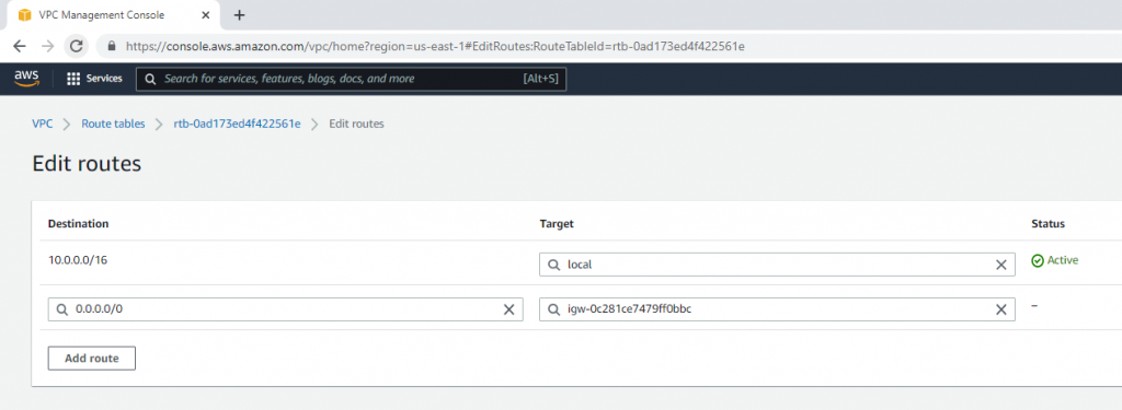
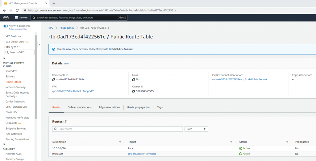
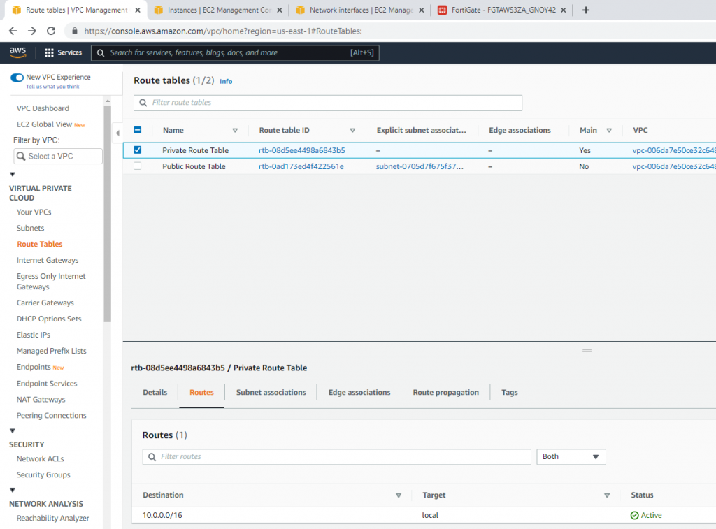
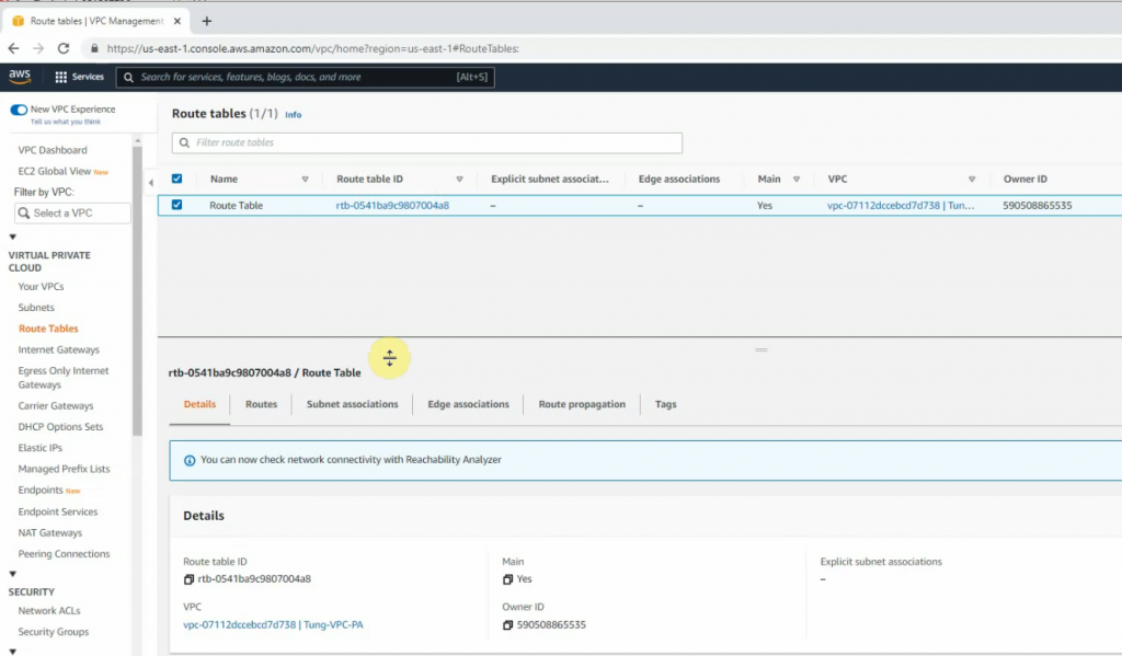
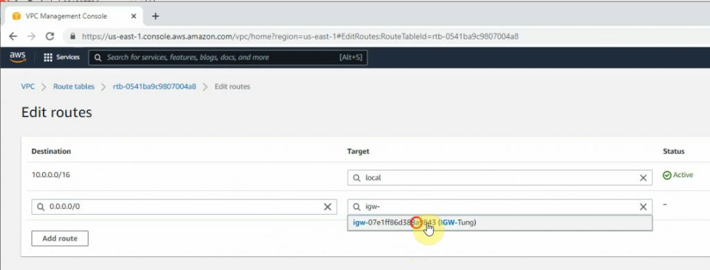
Route table.
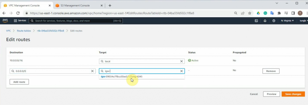
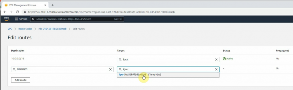
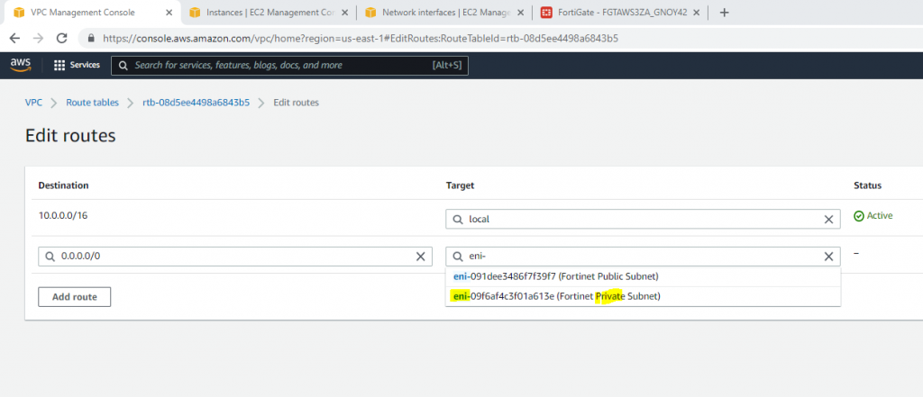
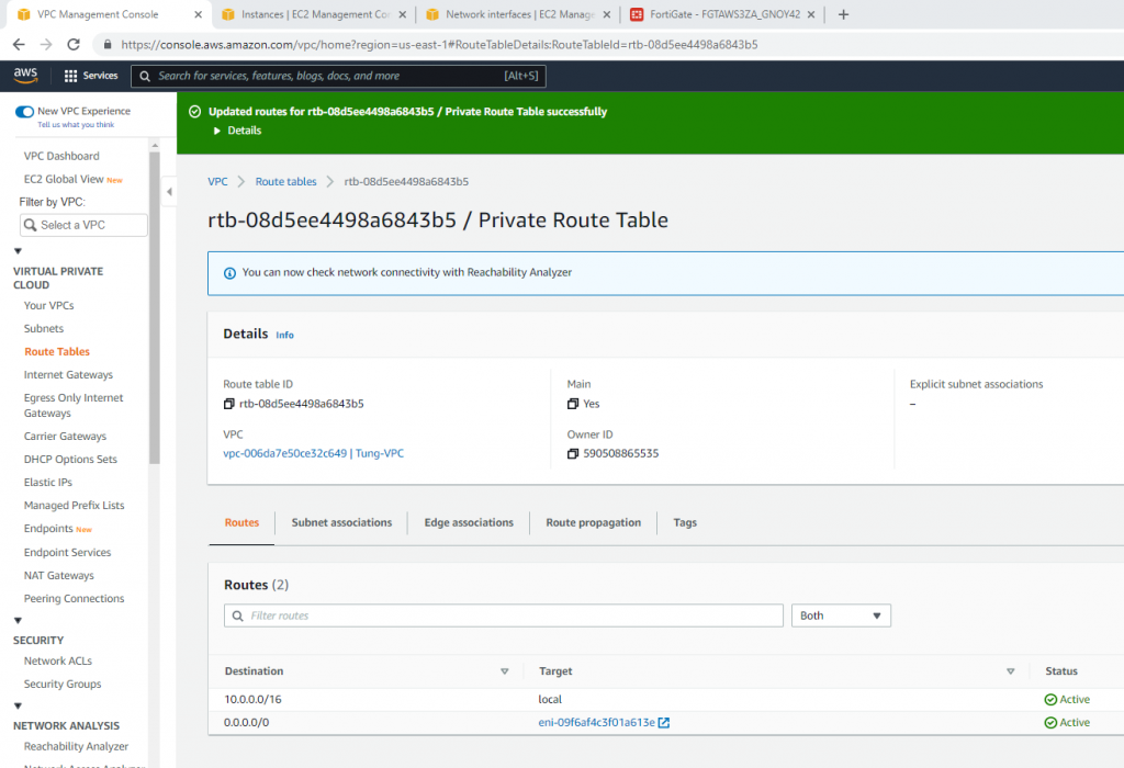
Add a new route to your Internet Gateway.
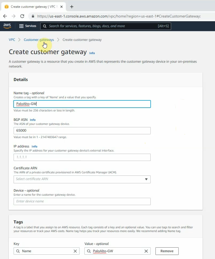
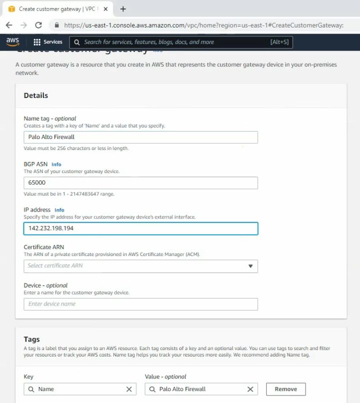
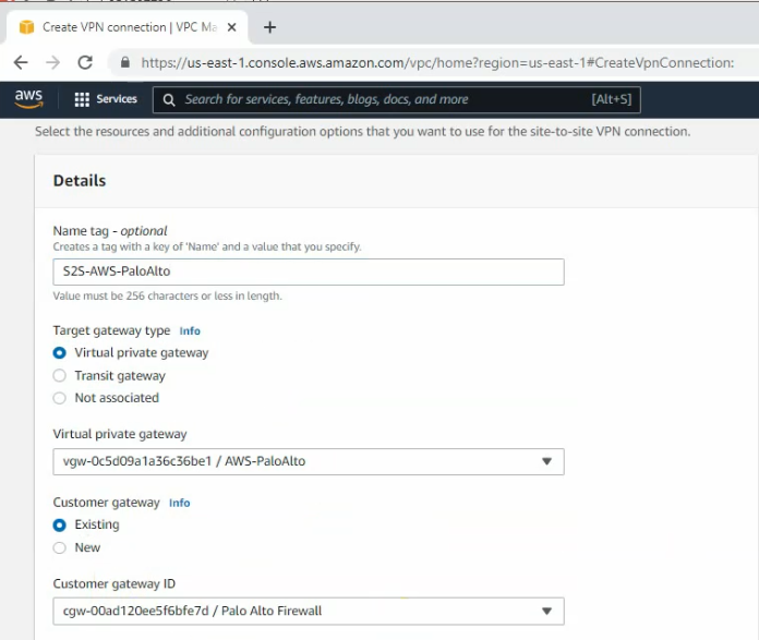
Go to VPN, create a customer gateway.
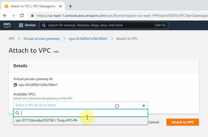
Create a new VPN gateway.
Attach it to your VPC.
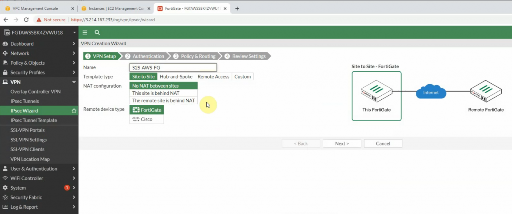
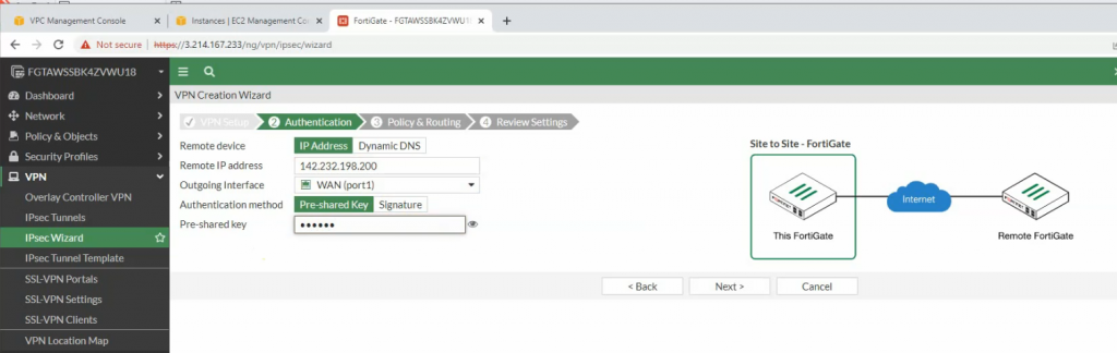
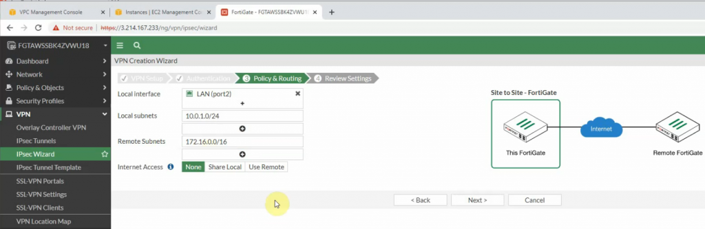
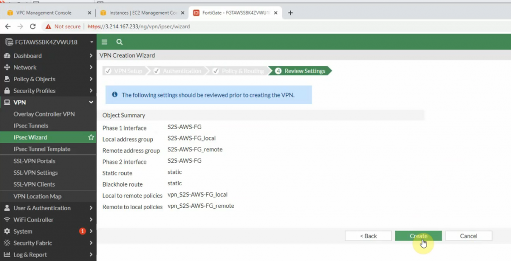
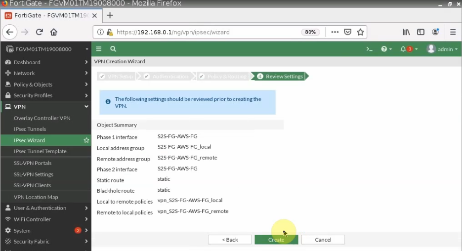
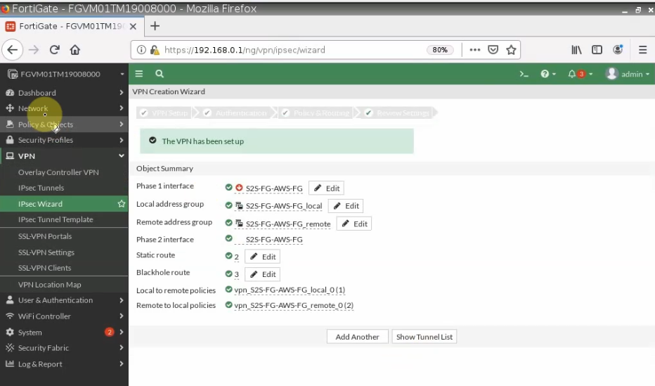
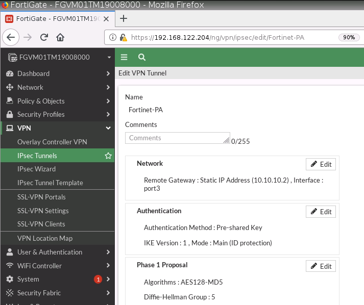
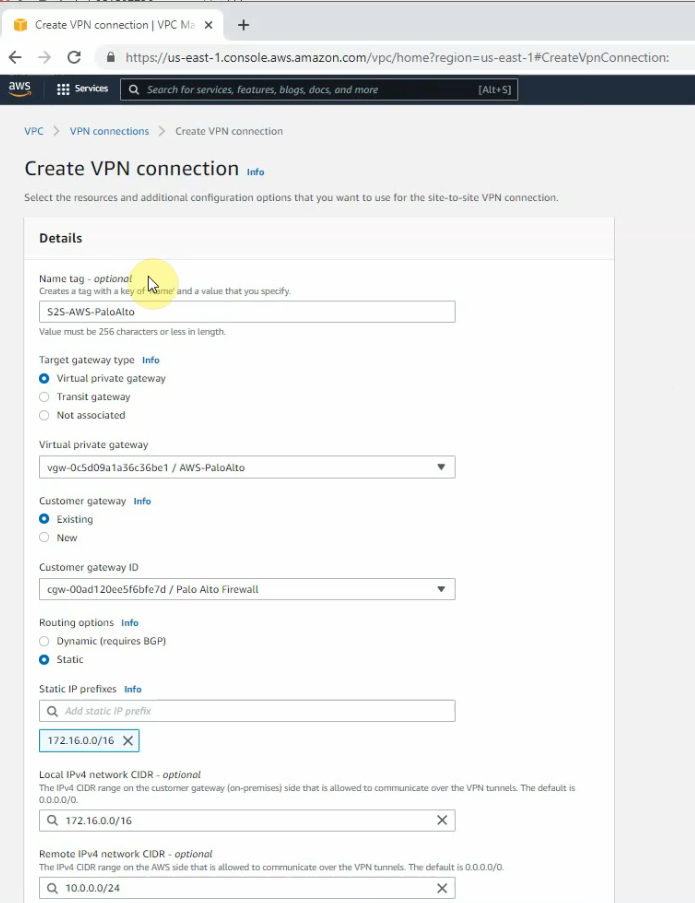
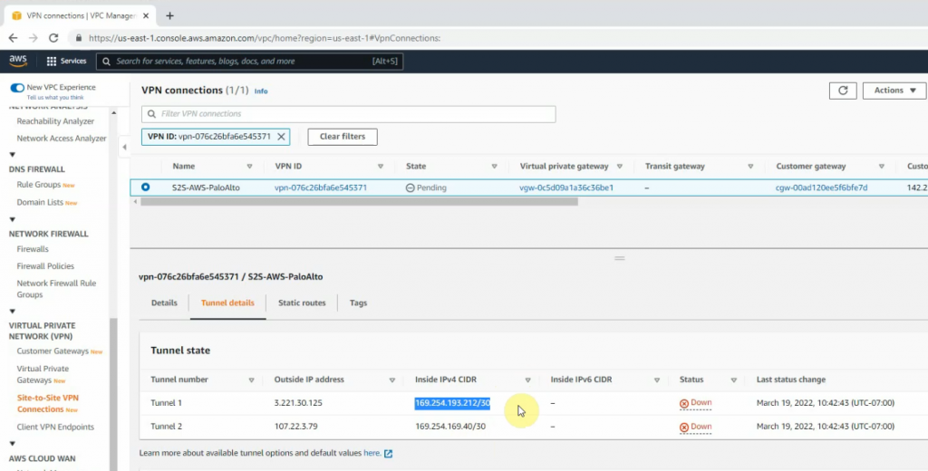
Create a VPN site to site.
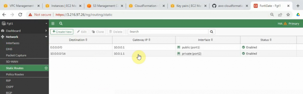
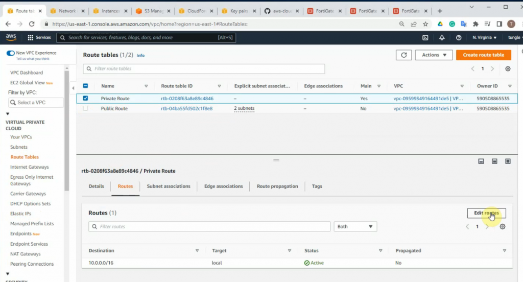
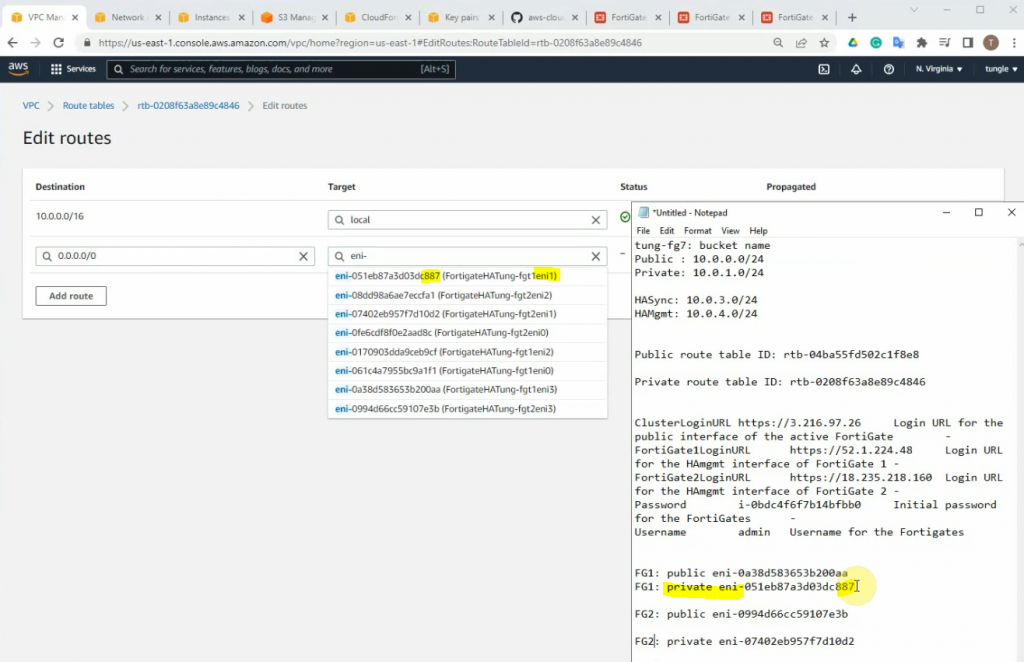
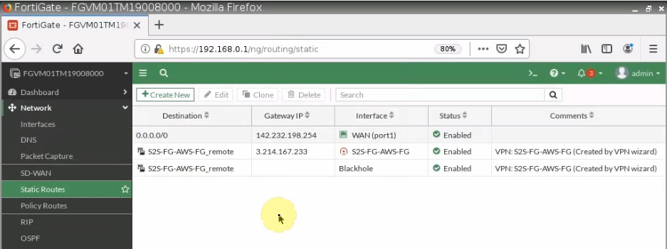
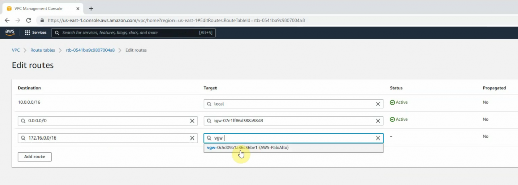
Go to the Route table and add a new route to PA LAN subnet.
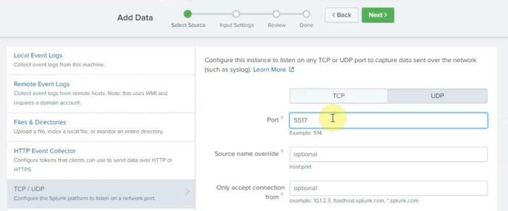
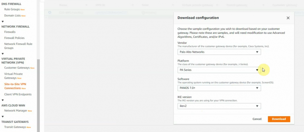
Click Download Configuration and select information as the following screenshot.
Open the file to use for configuring PA.
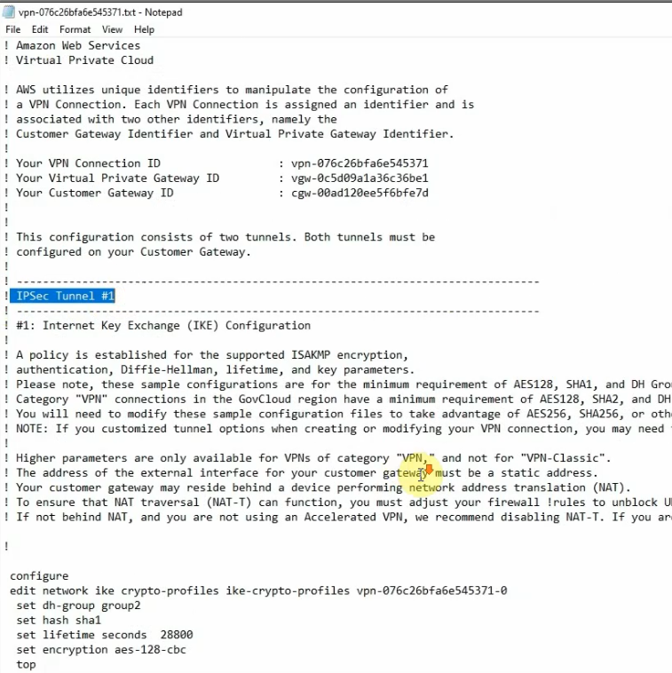
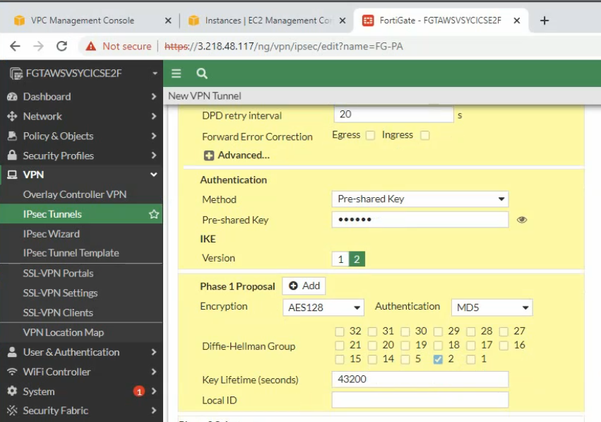
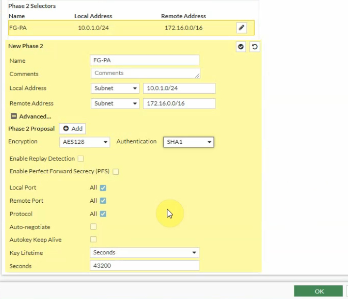
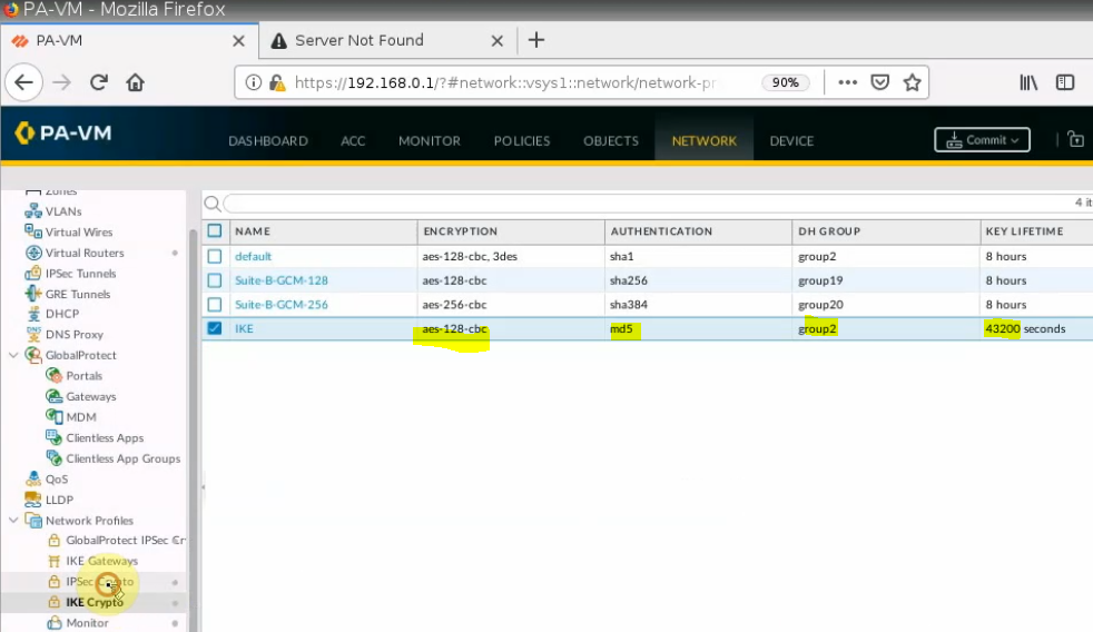
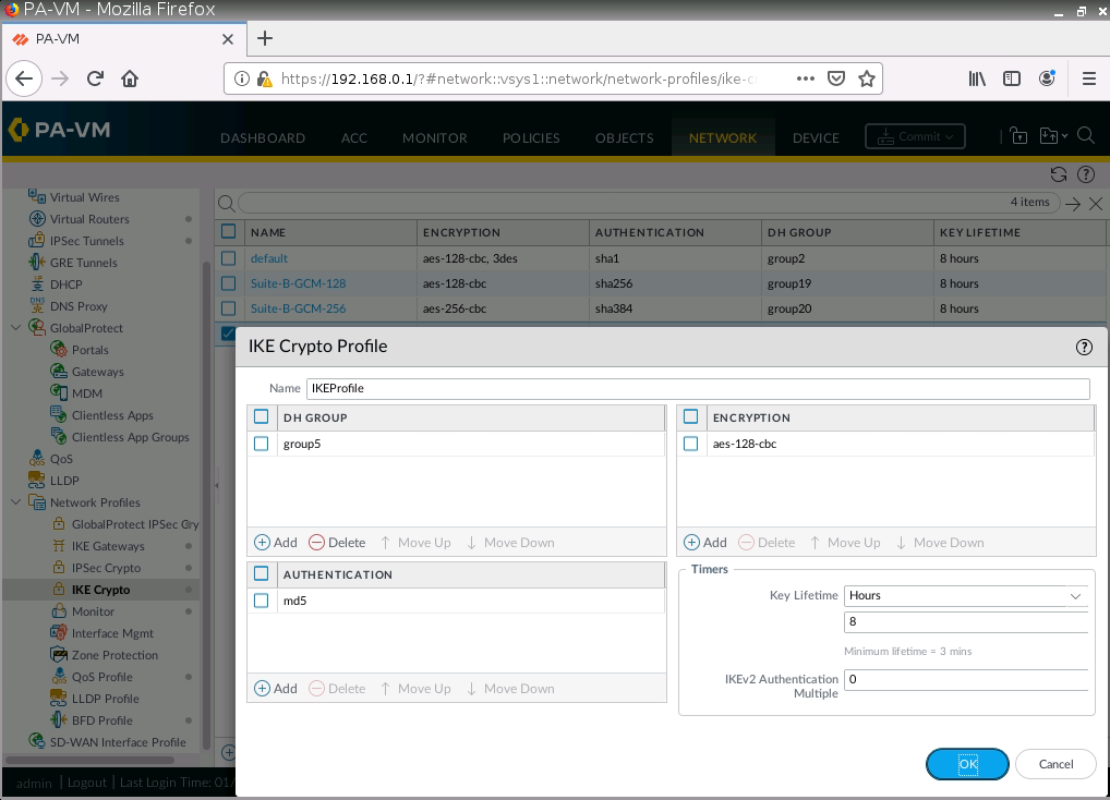
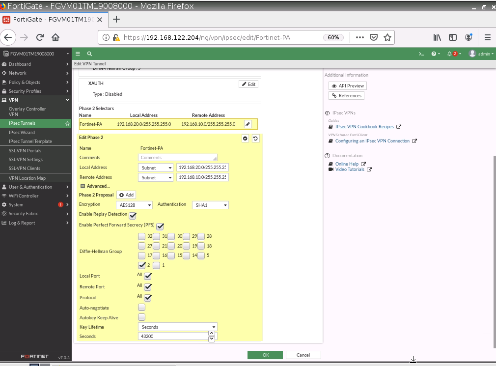
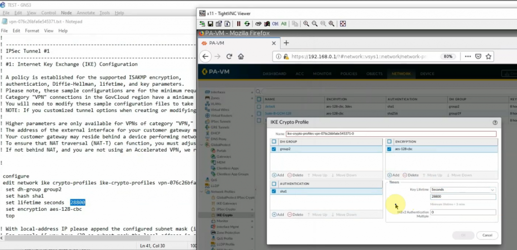
Configure IKECrypto.
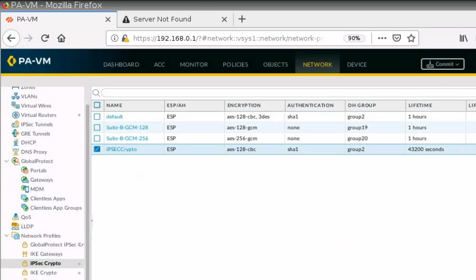
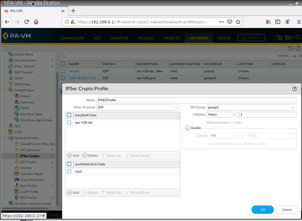
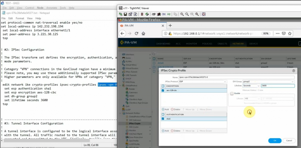
Configure IPSECCrypto.
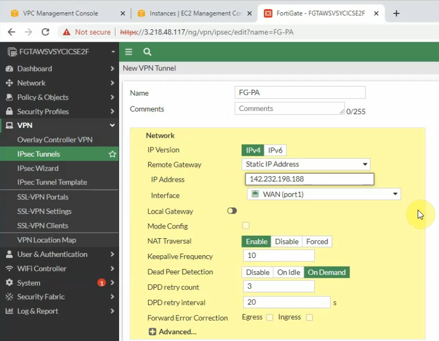
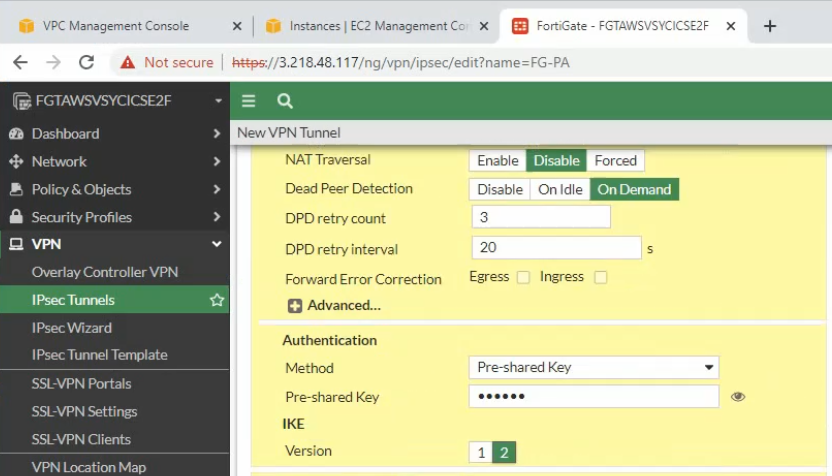
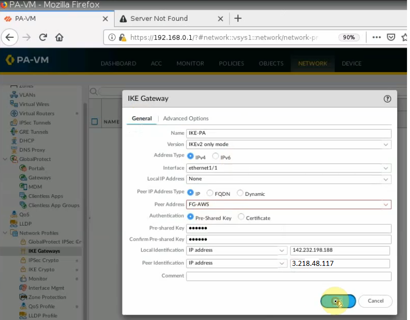
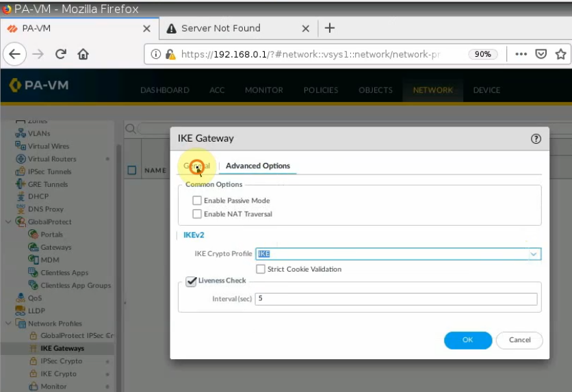
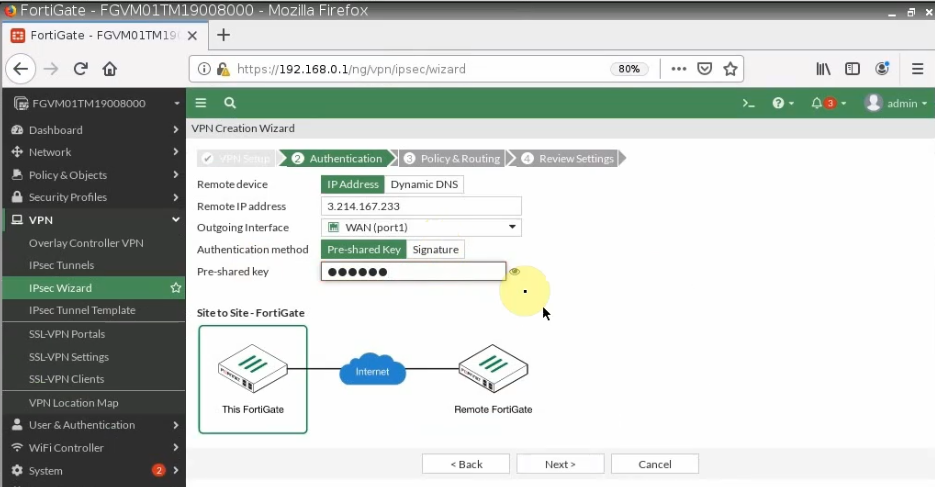
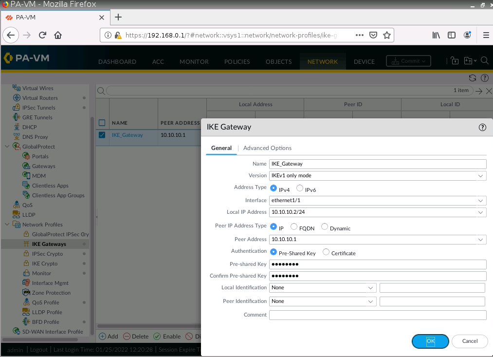
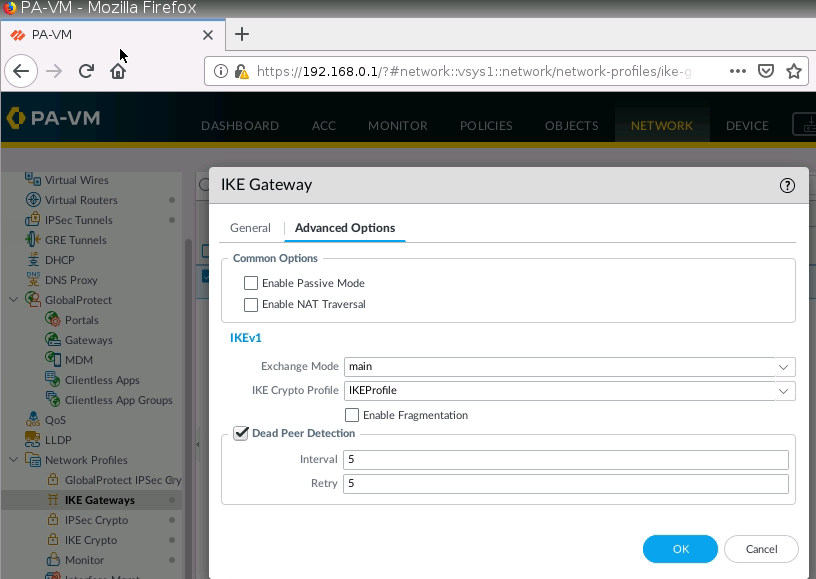
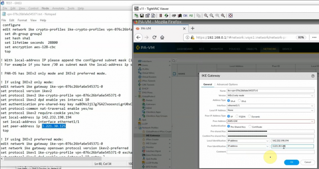
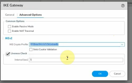
Configure IKE Gateway.
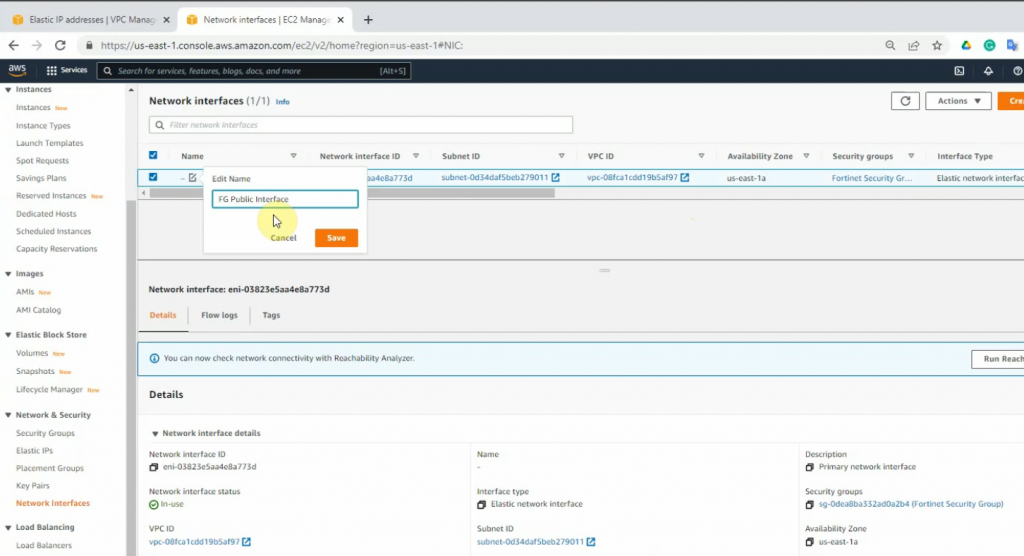
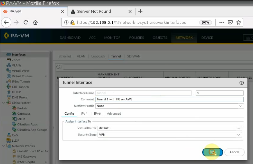
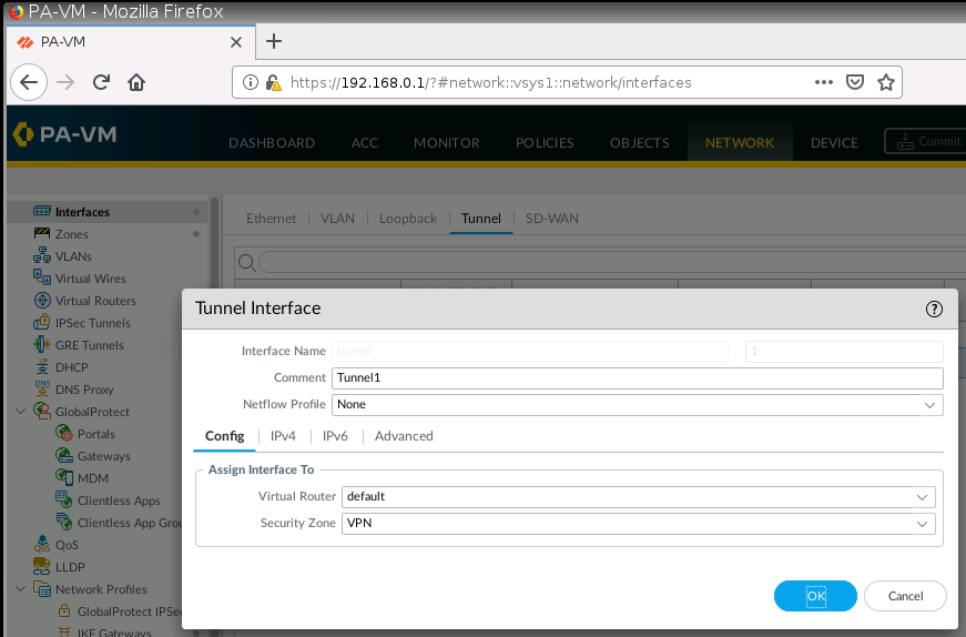
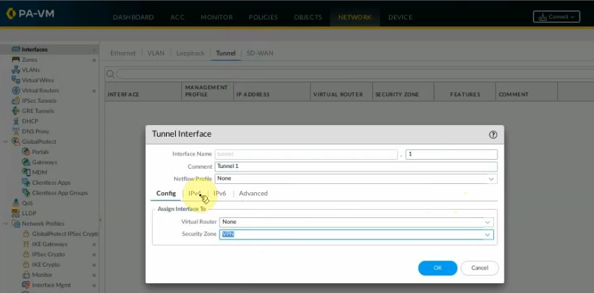
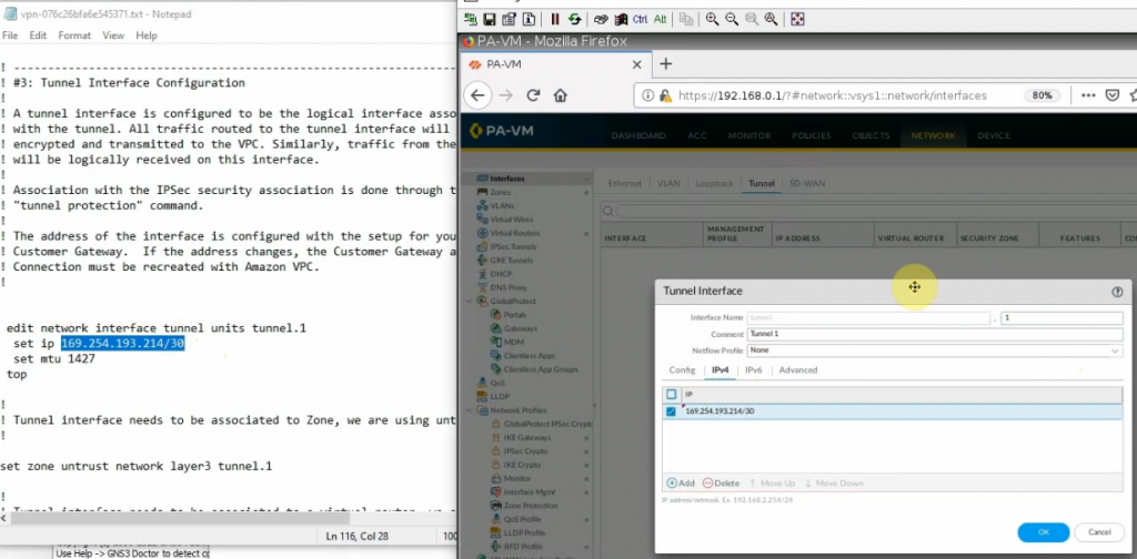
Create a new interface tunnel 1 for VPN IPSEC site to site between FG on AWS and PA.
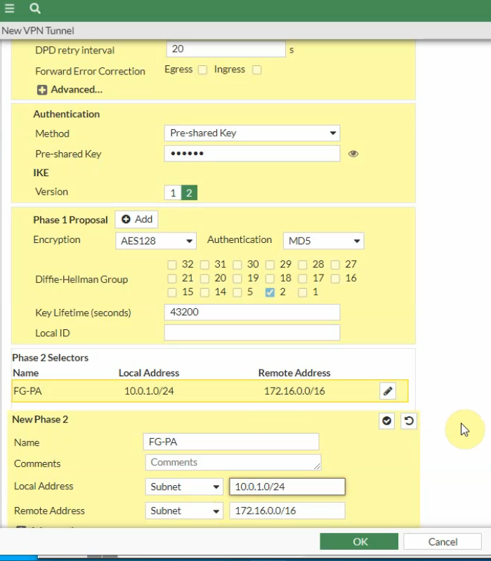
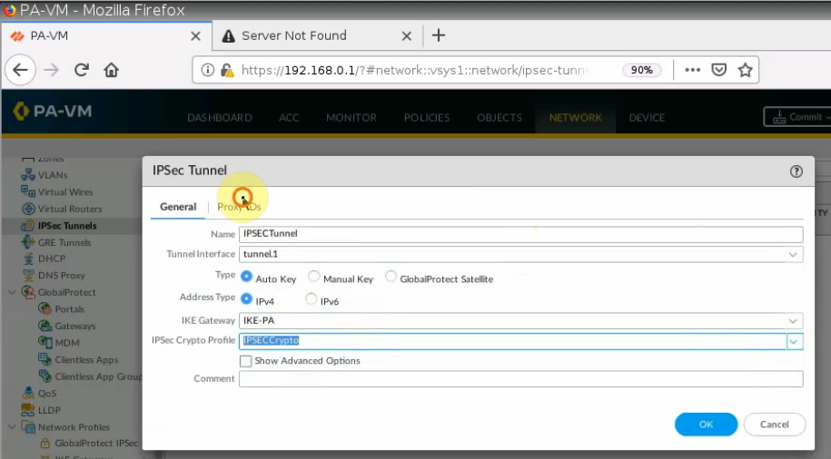
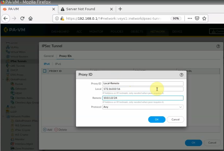
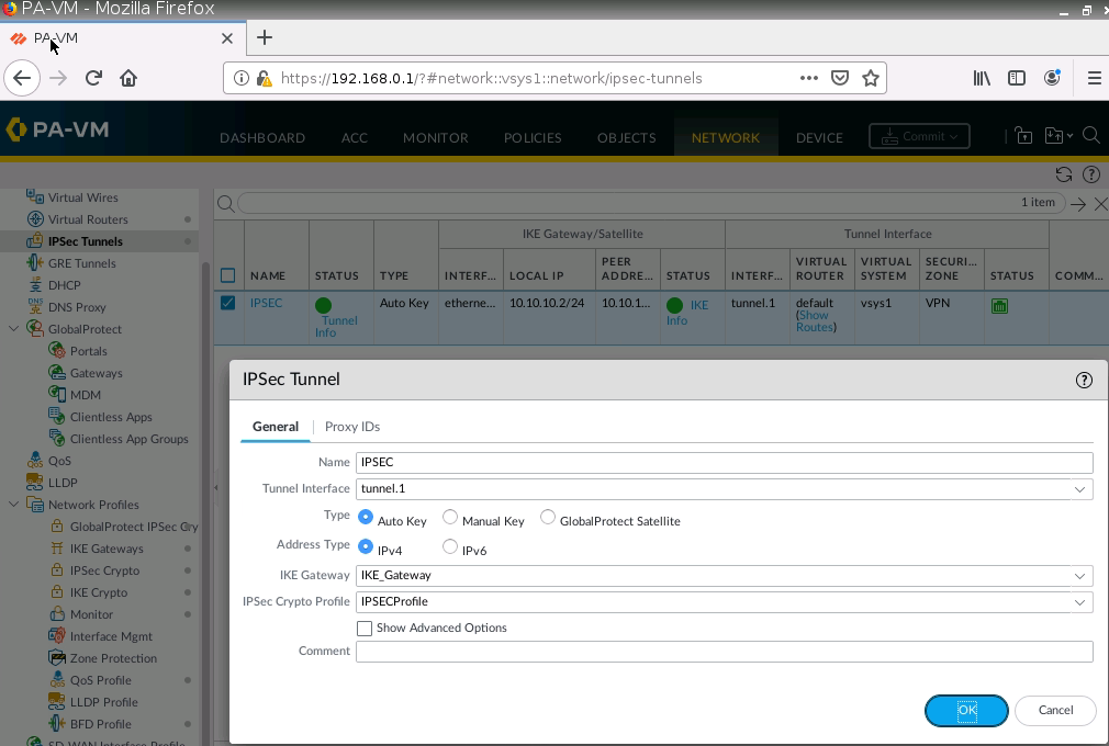
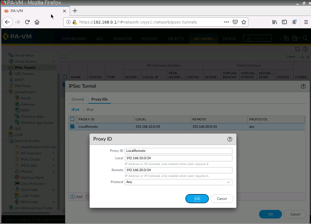
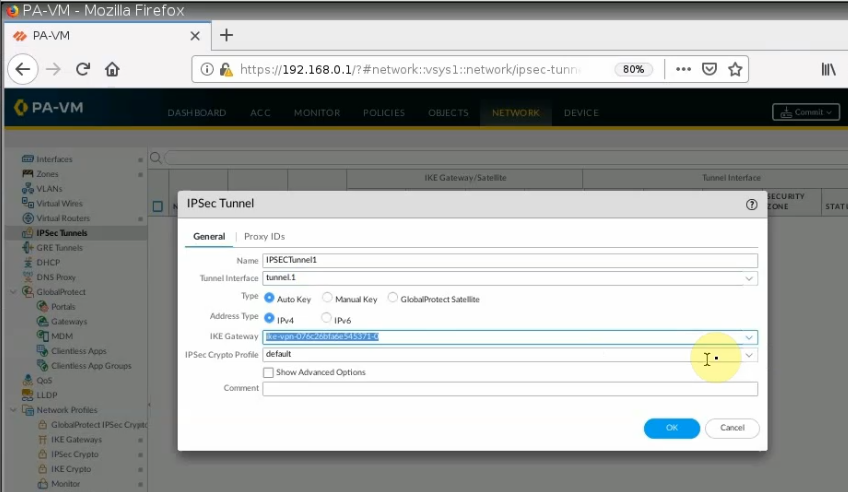
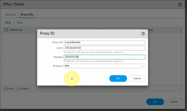
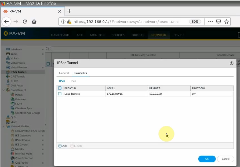
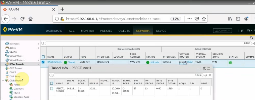
Configure IPSEC Tunnel.
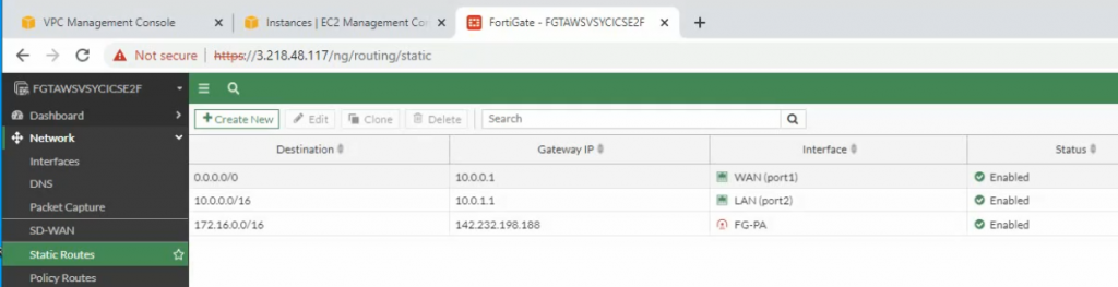
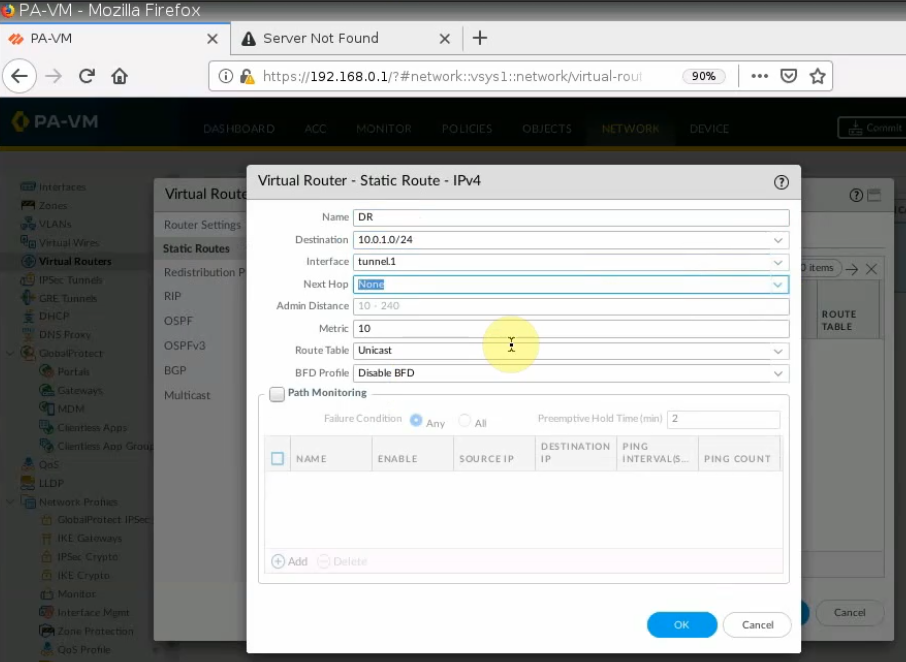
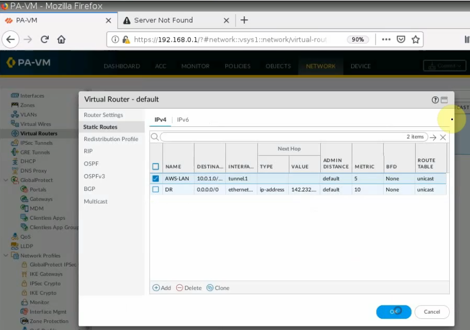
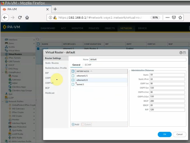
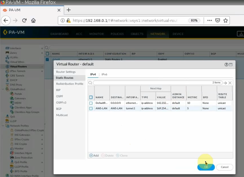
On Virtual Routers, add an interface tunnel 1 on the router settings.
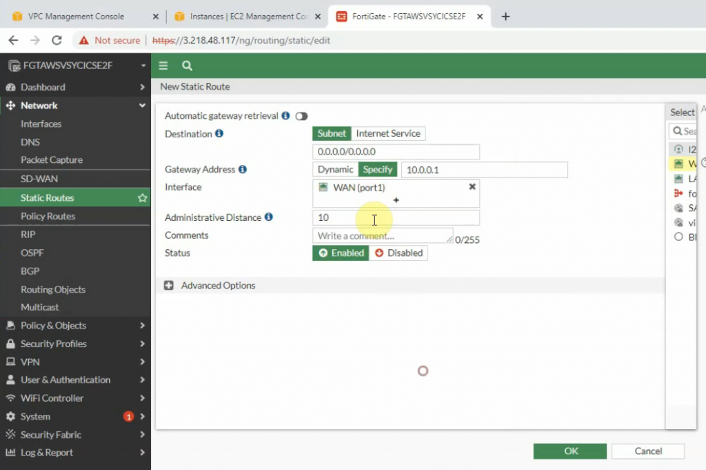
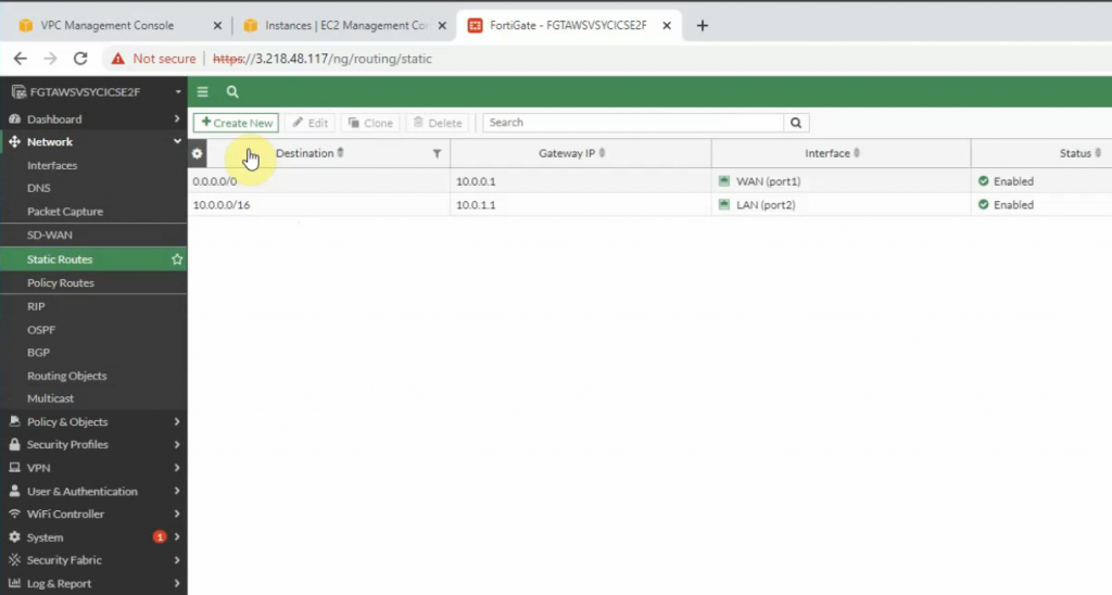
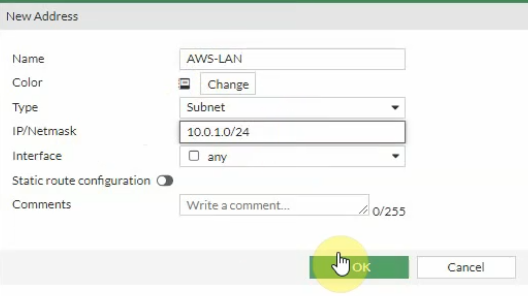
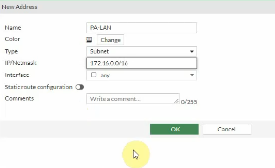
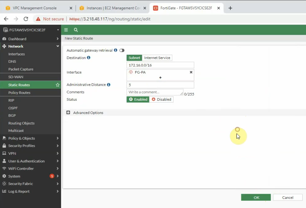
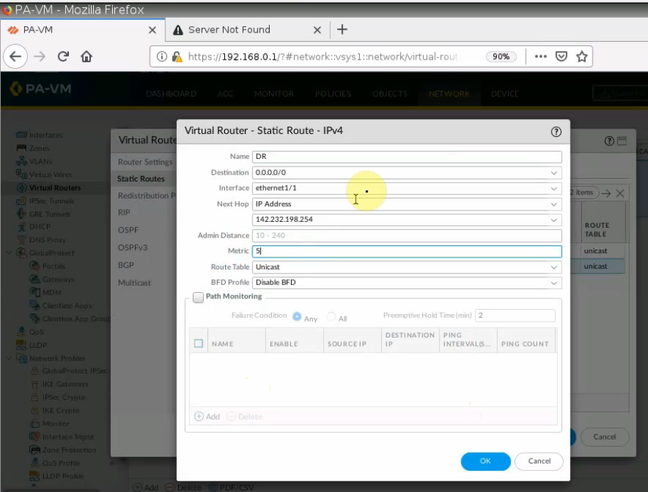
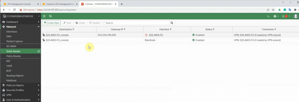
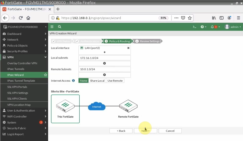
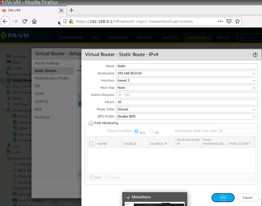
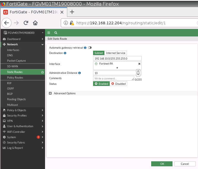
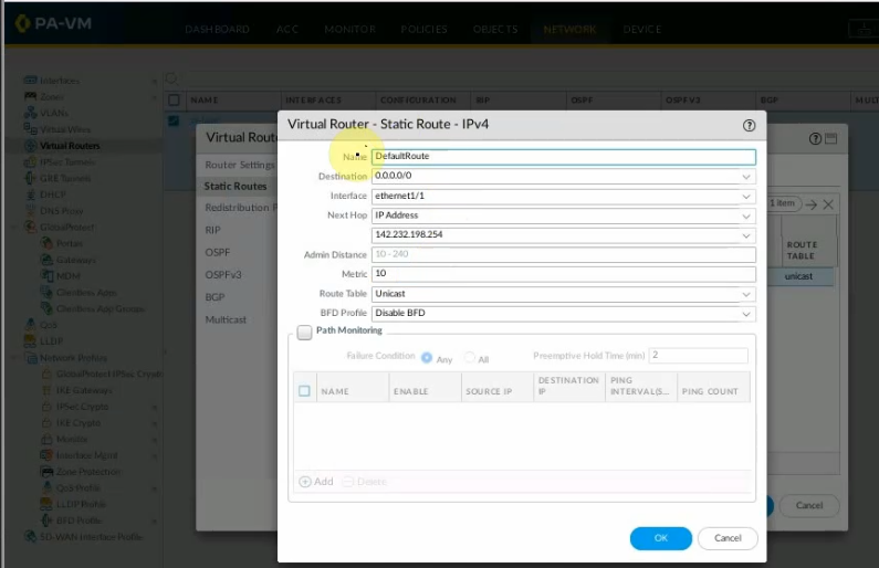
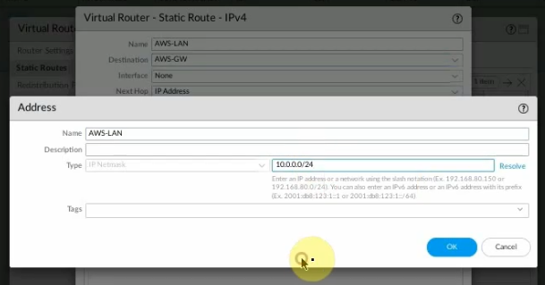
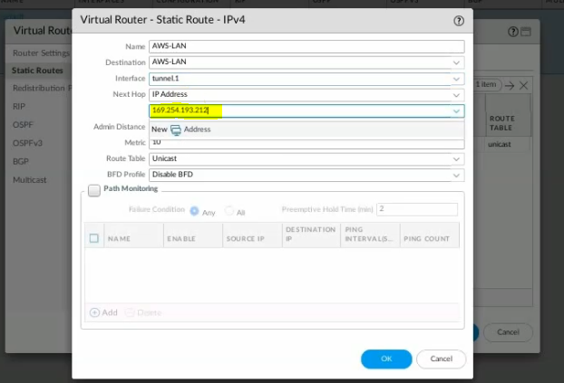
Create a new static route to the AWS LAN subnet.
New address object.
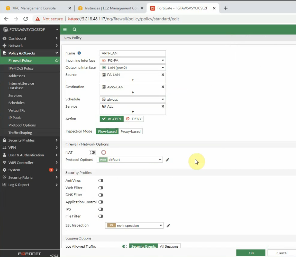
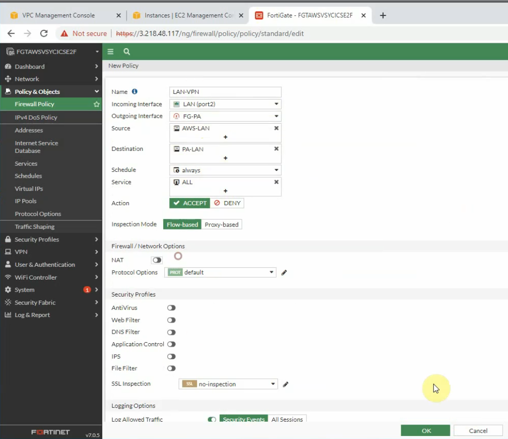
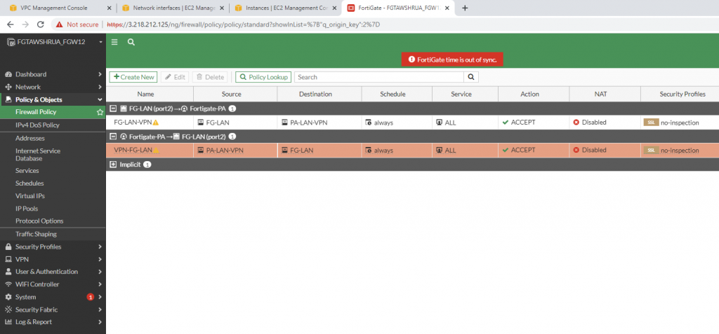
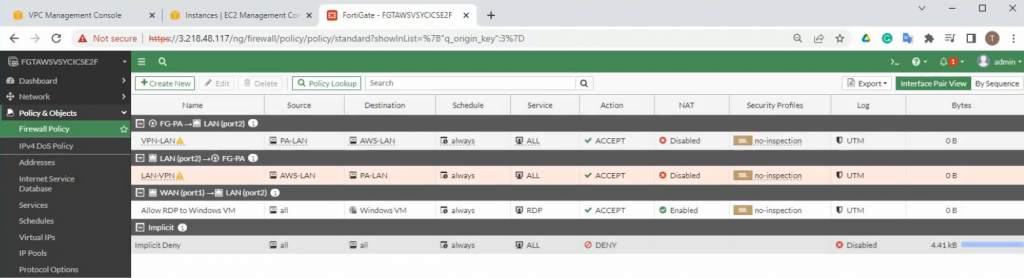
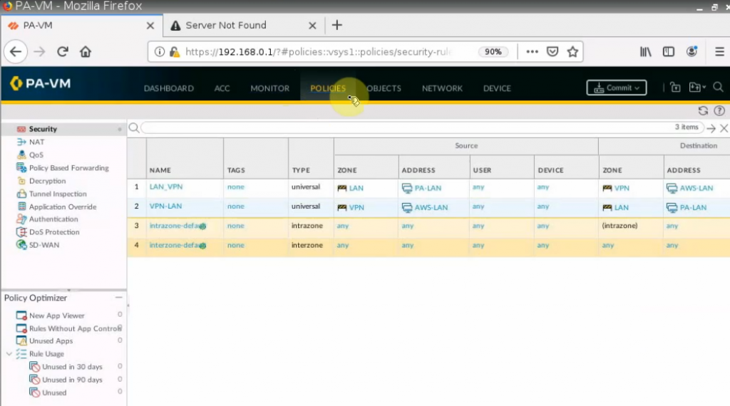
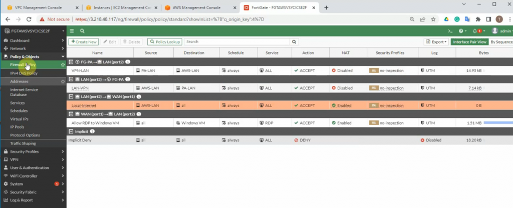
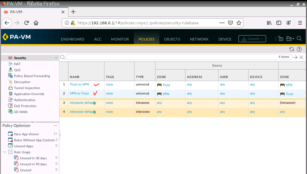
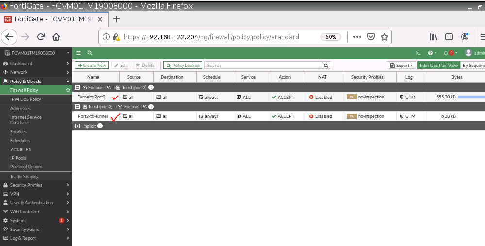
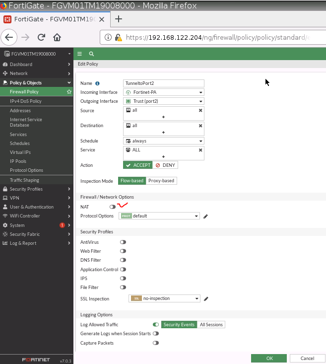
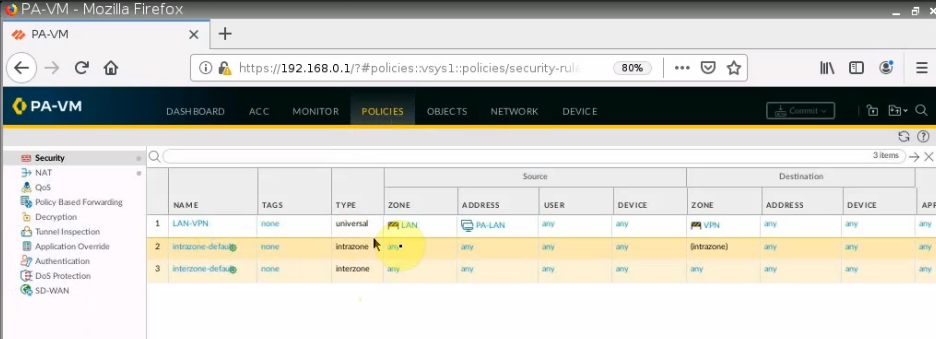
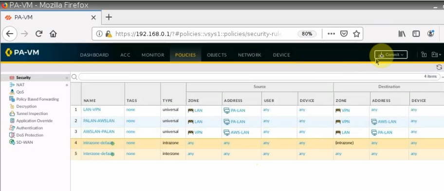
Create both Security policies to allow traffic from LAN to VPN.
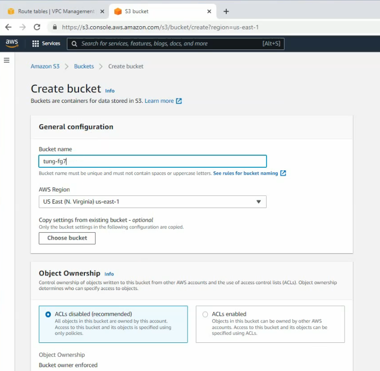
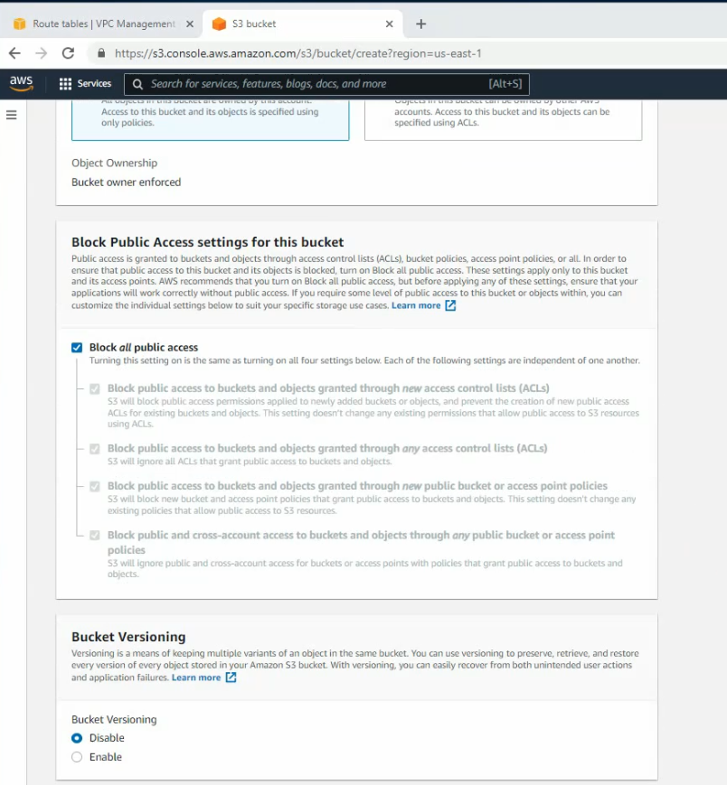
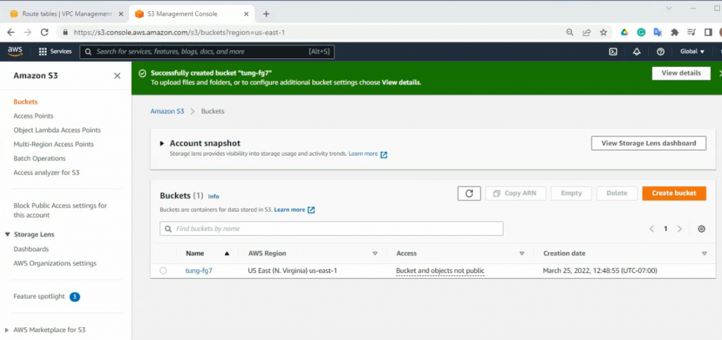
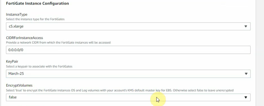
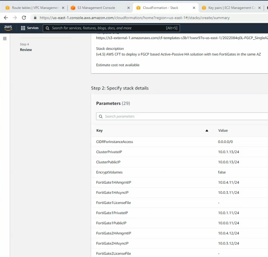
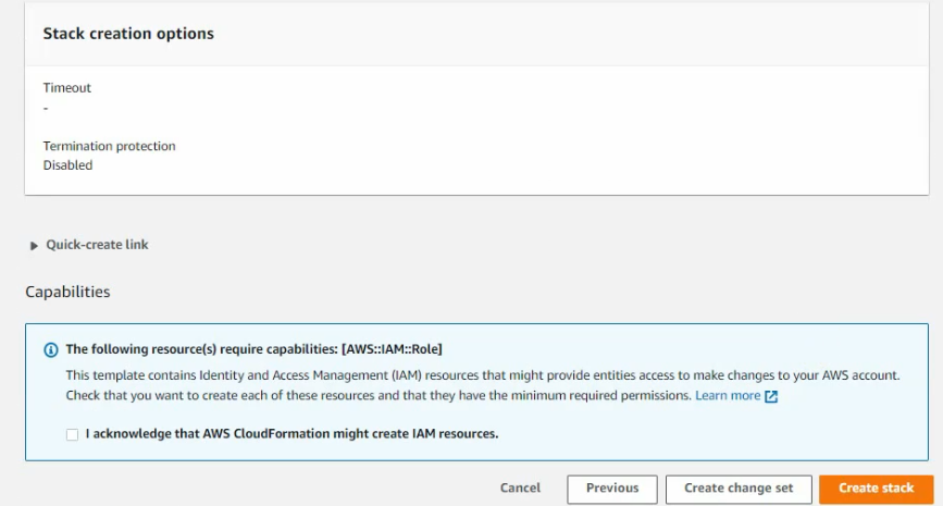
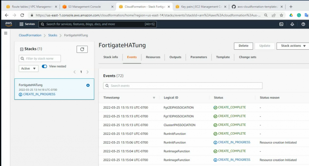
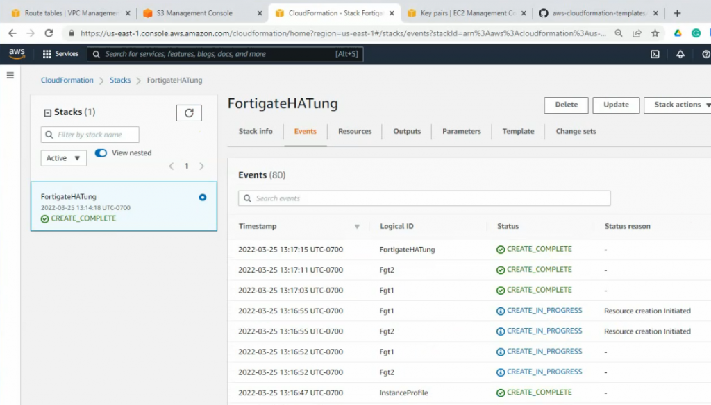
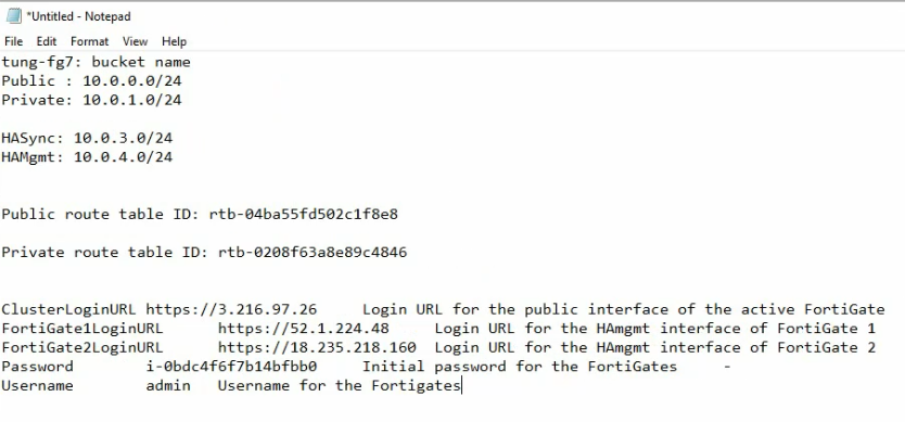
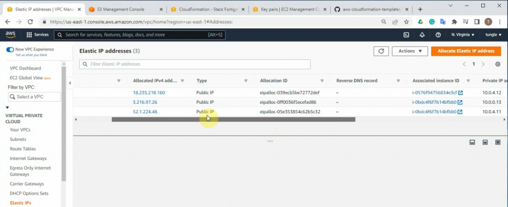
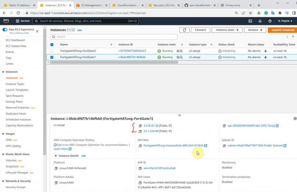
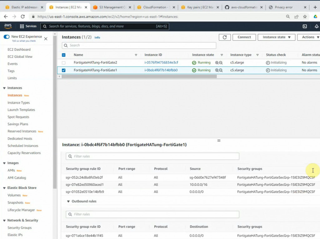
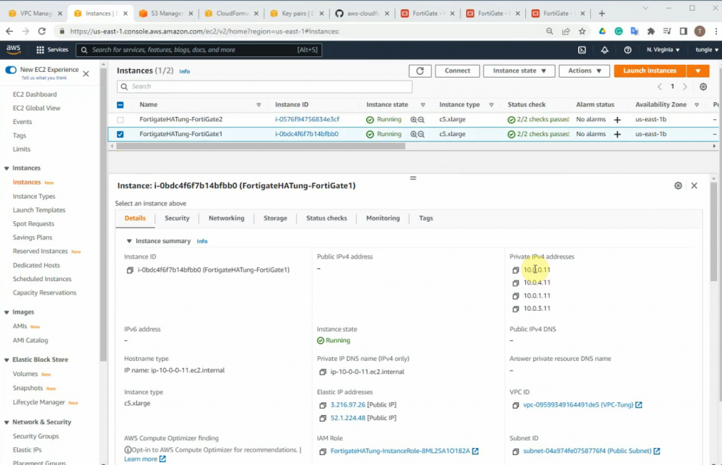
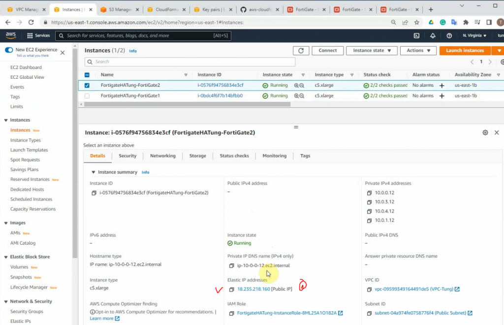
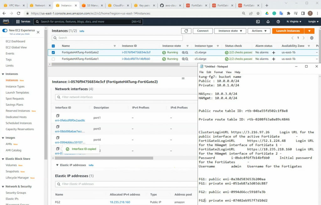
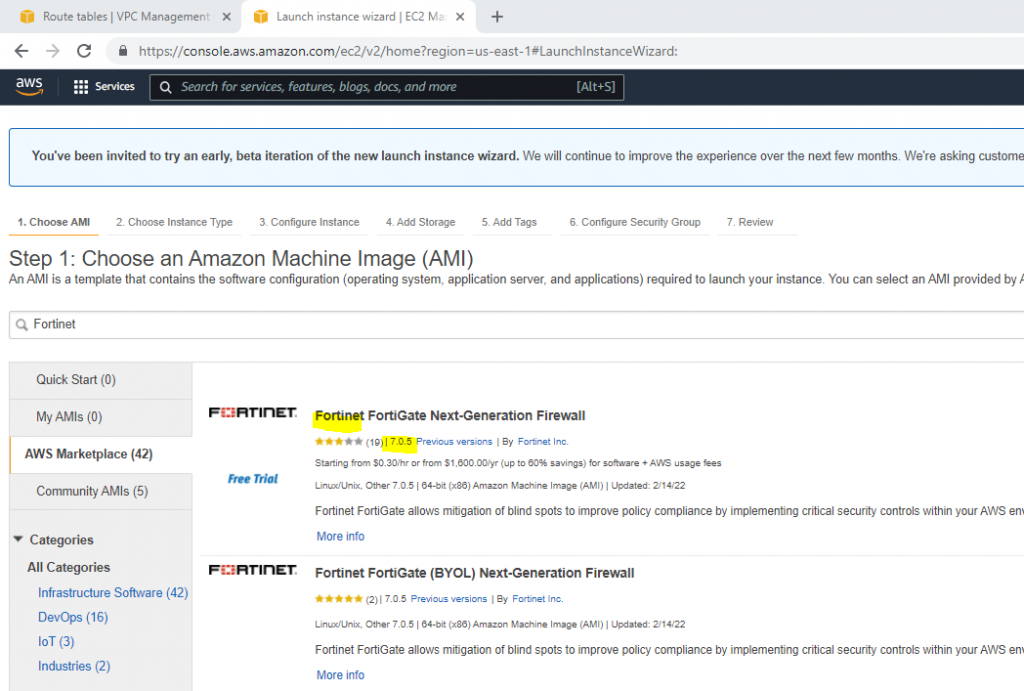
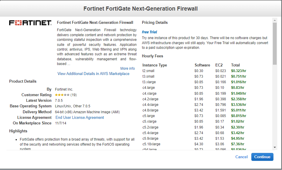
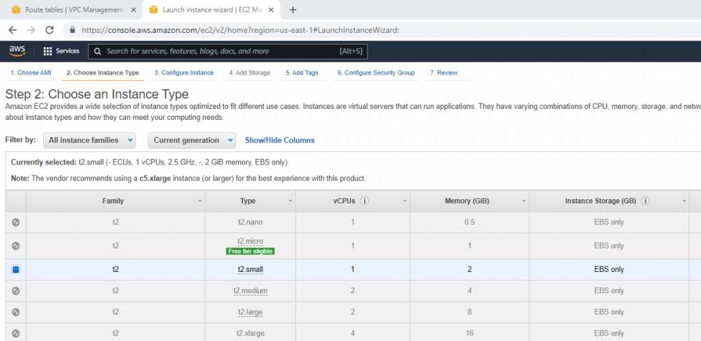
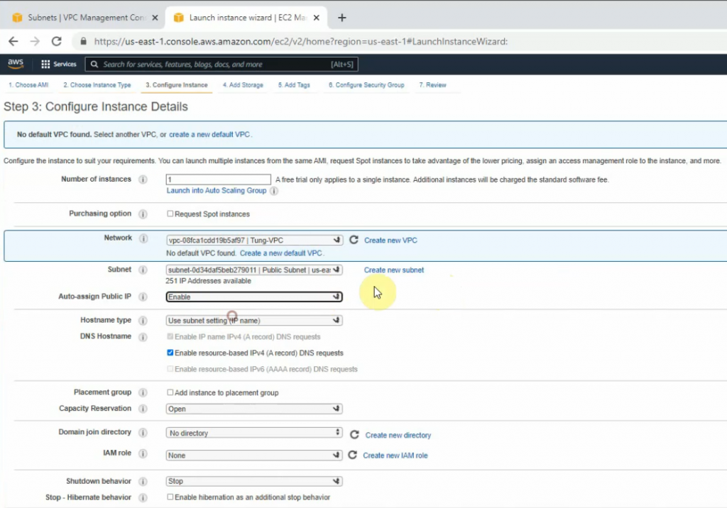
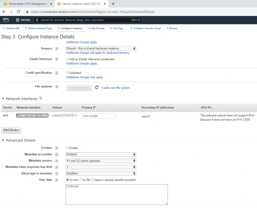
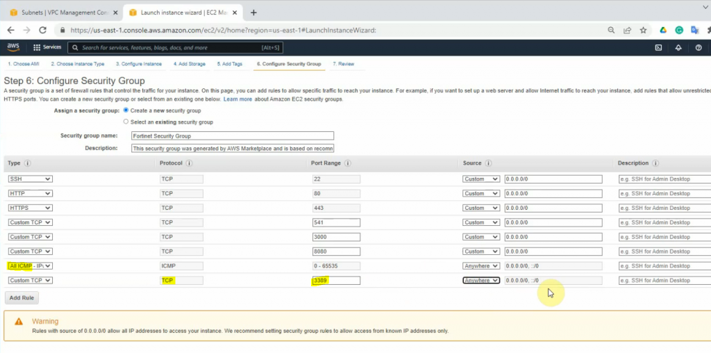
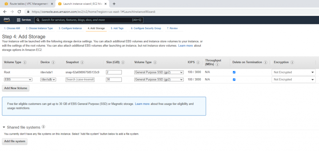
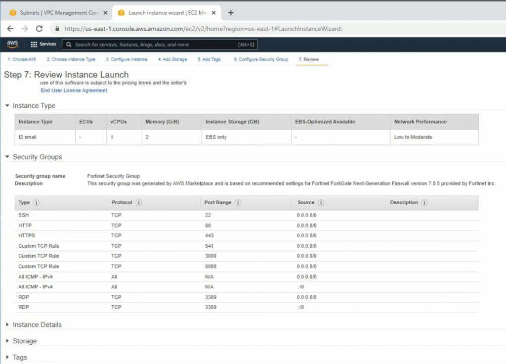
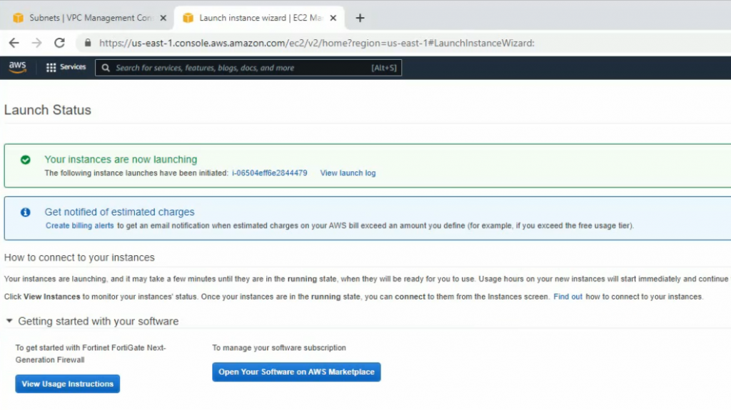
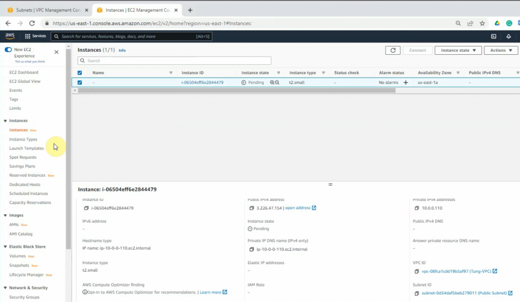
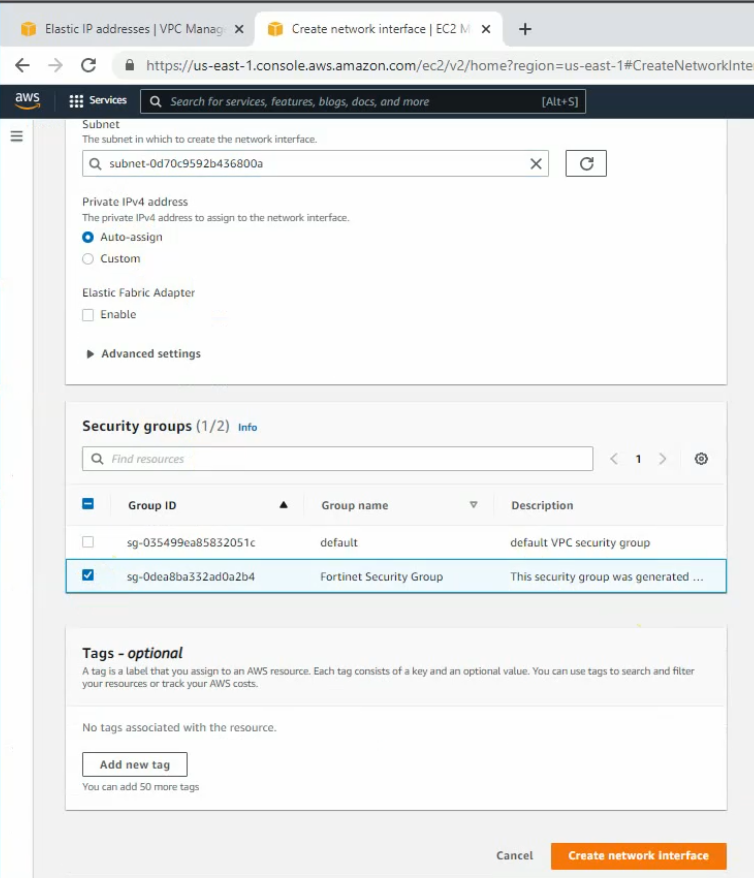
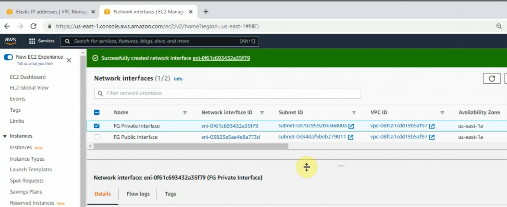
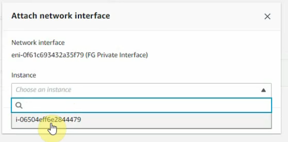
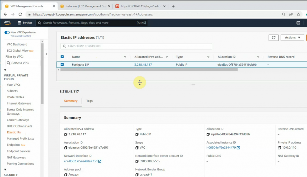
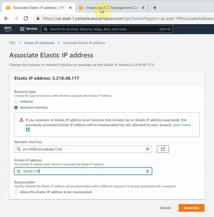
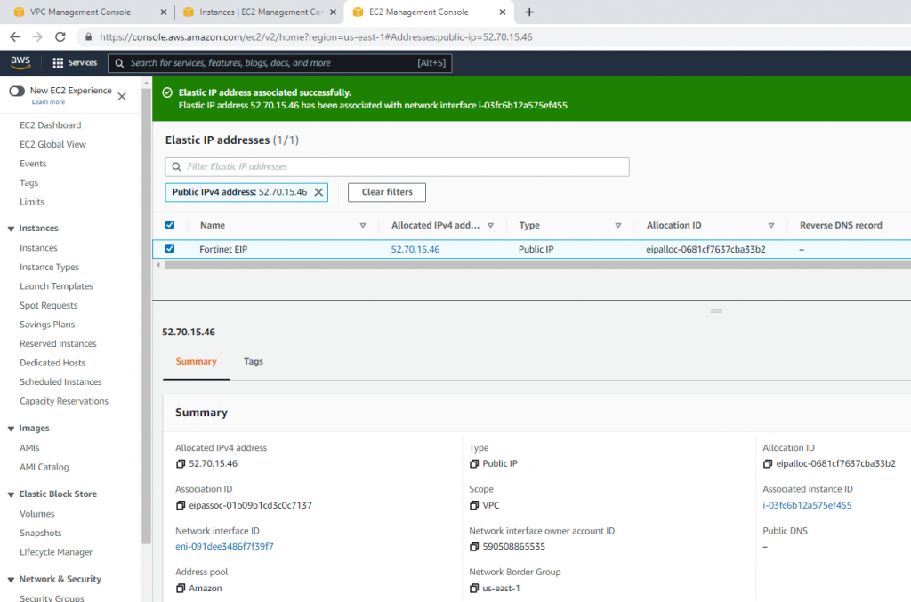
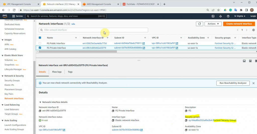
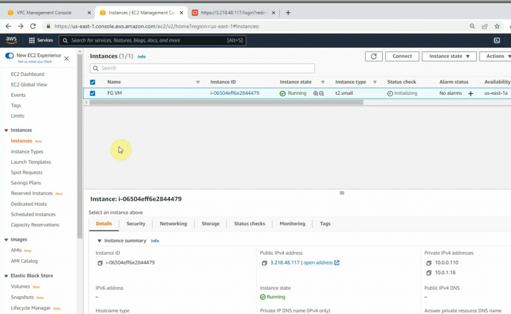
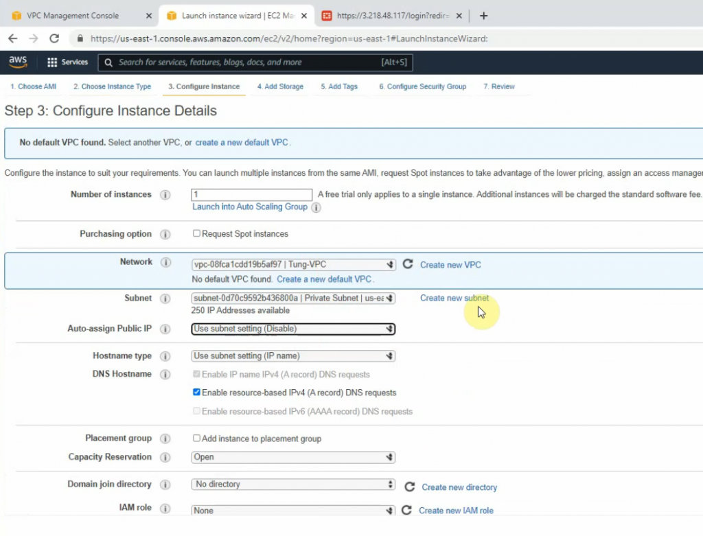
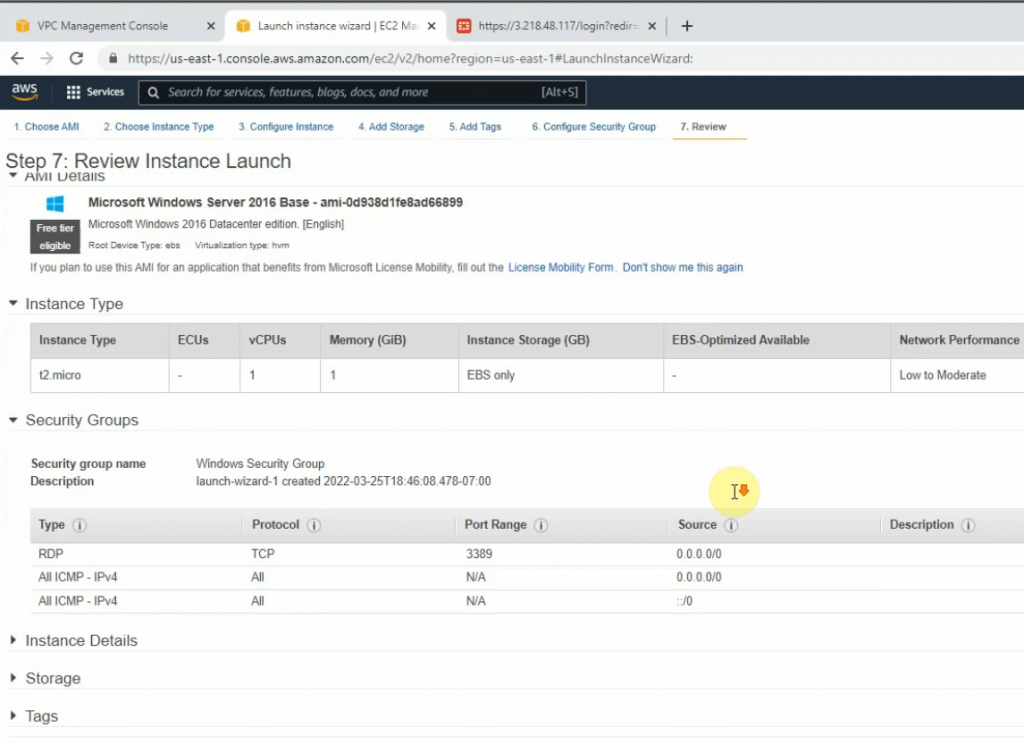
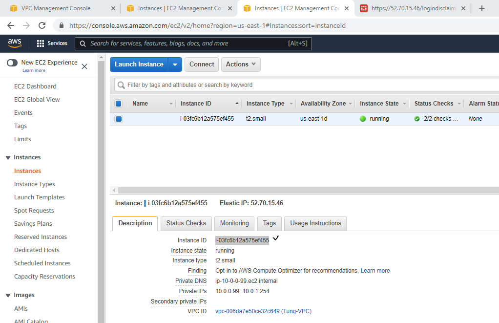
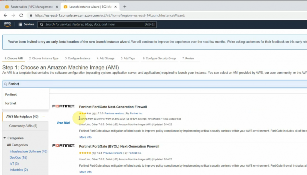
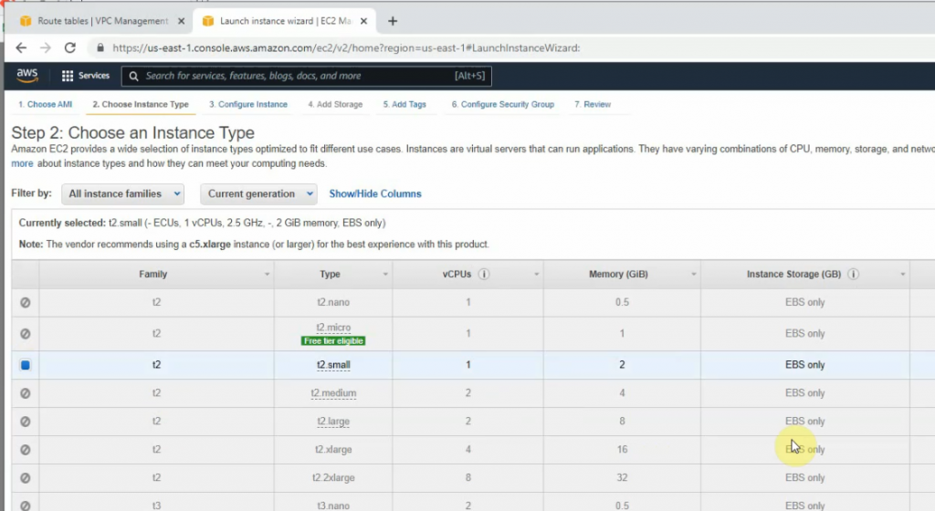
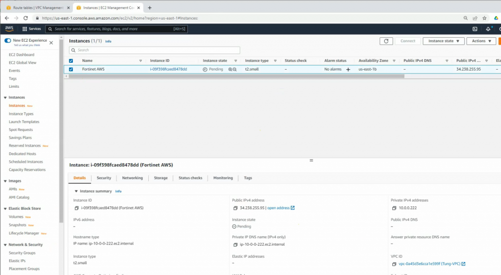
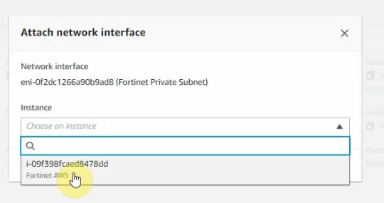
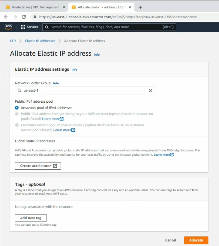
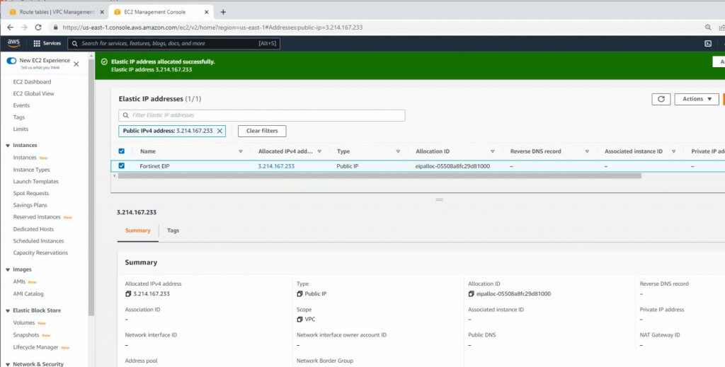
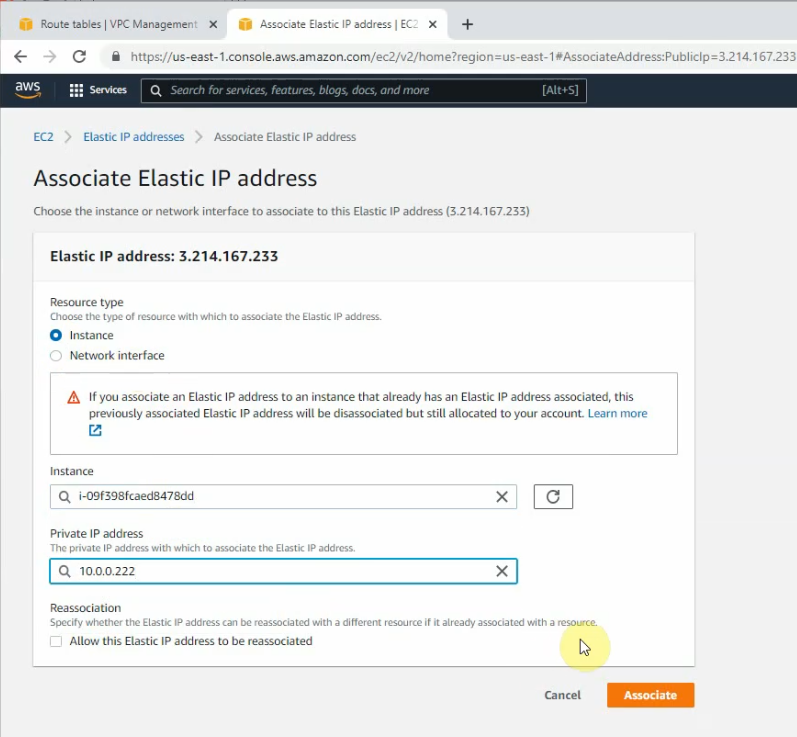
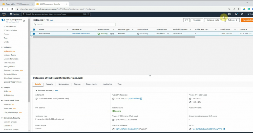
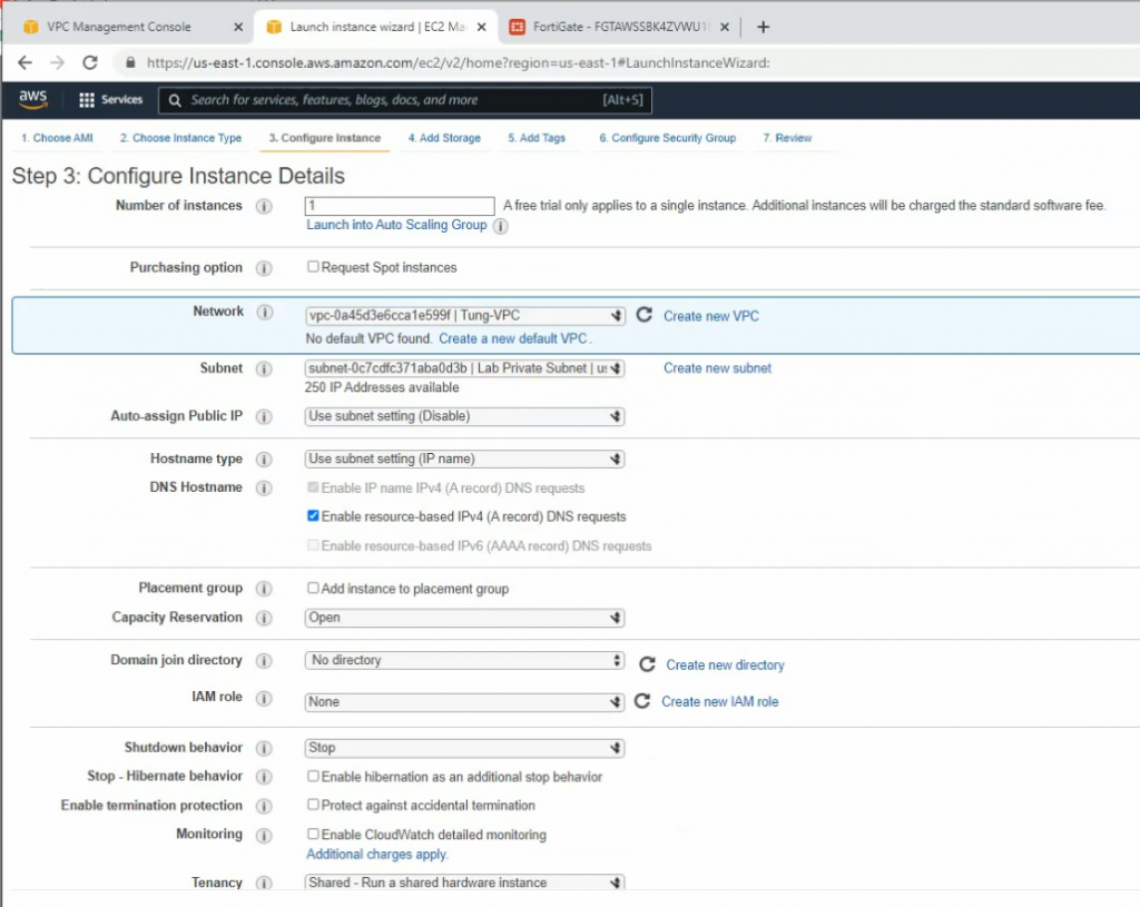
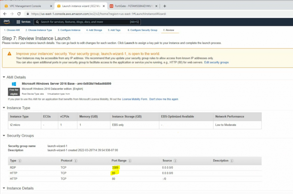
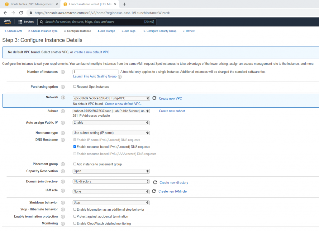
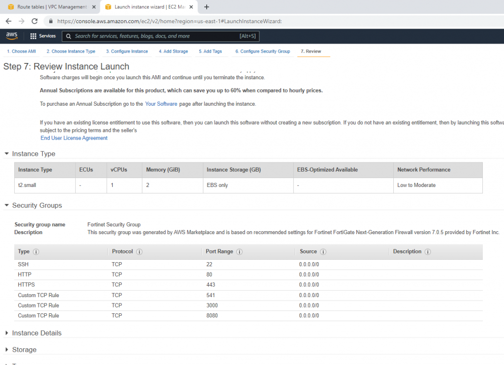
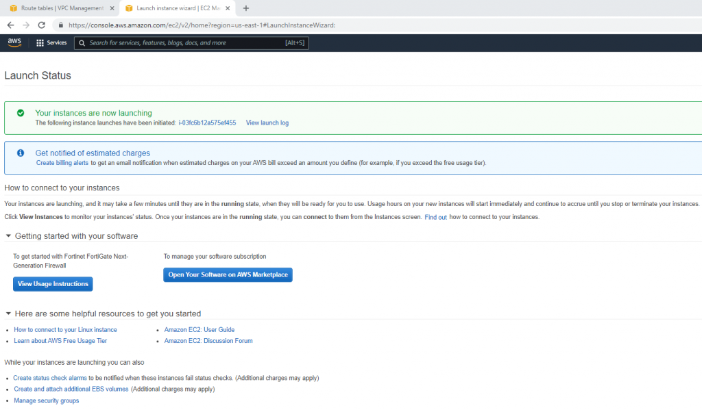
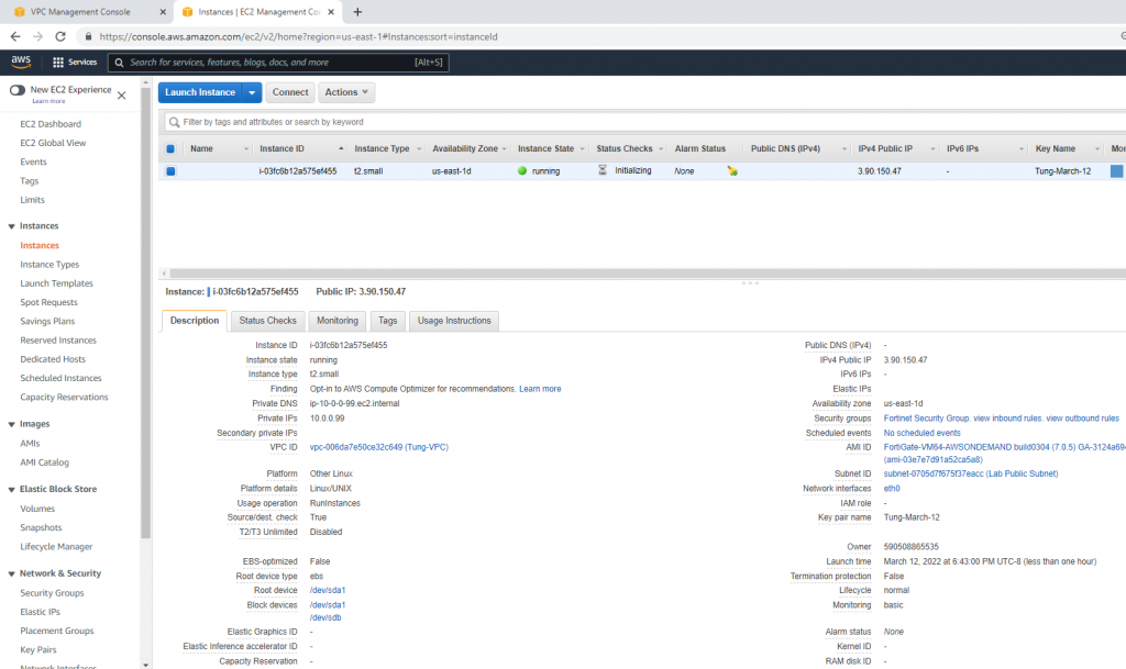
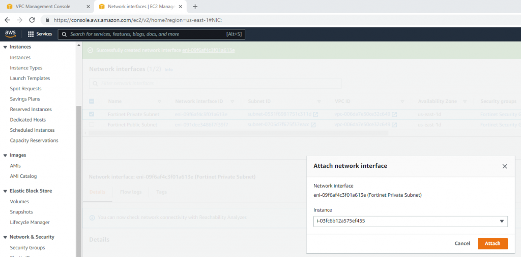
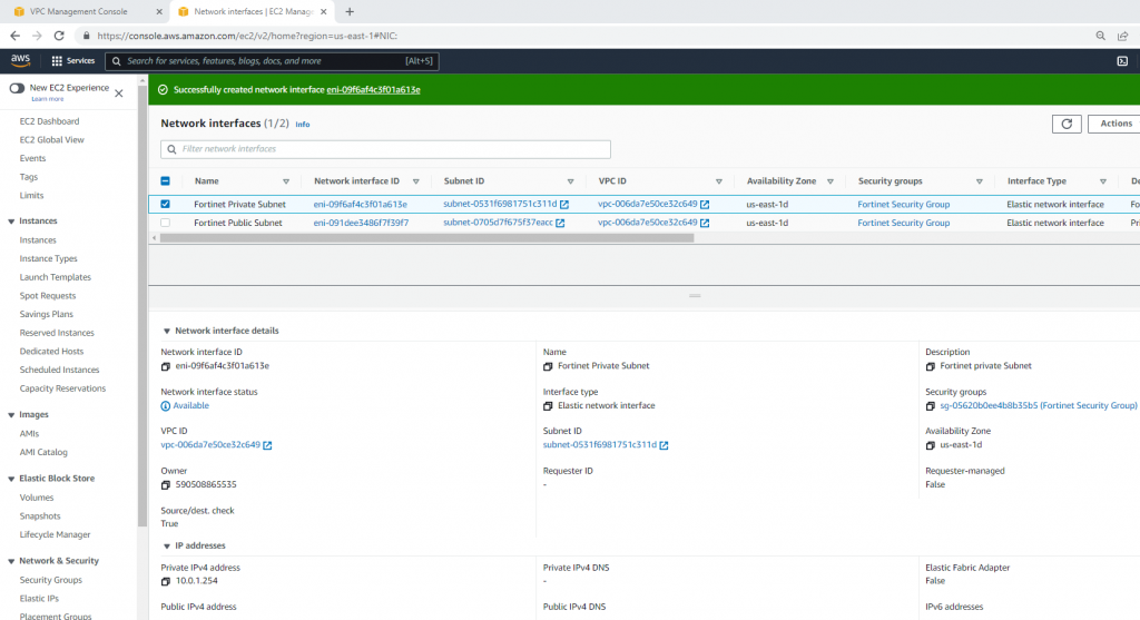
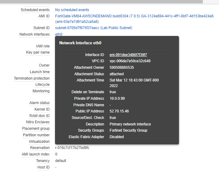
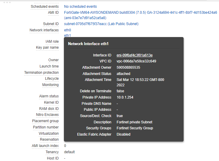
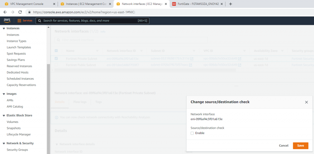
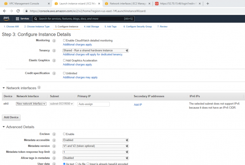
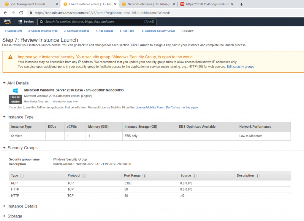
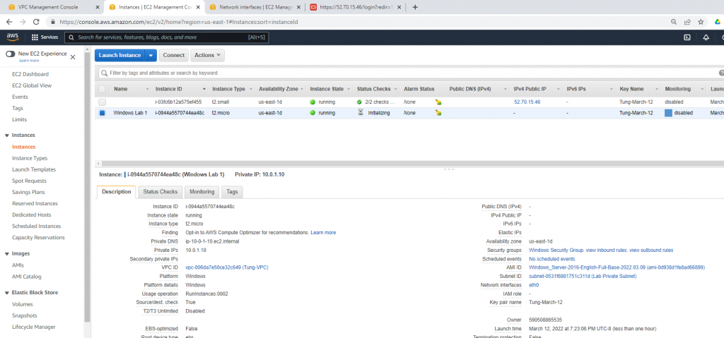
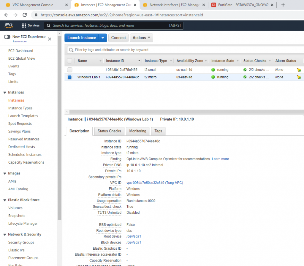
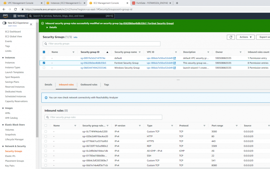
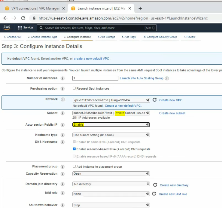
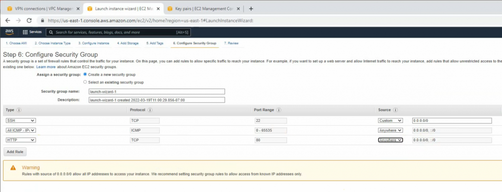
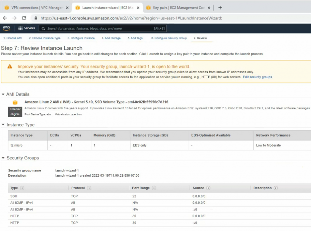
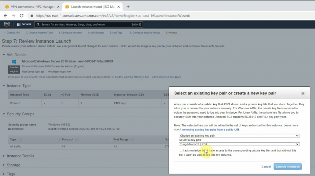
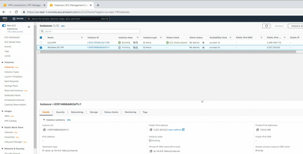
+ Back to AWS, create a new Linux and Windows instance on AWS.
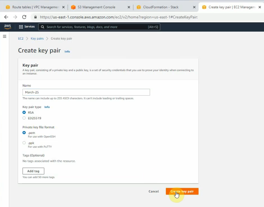
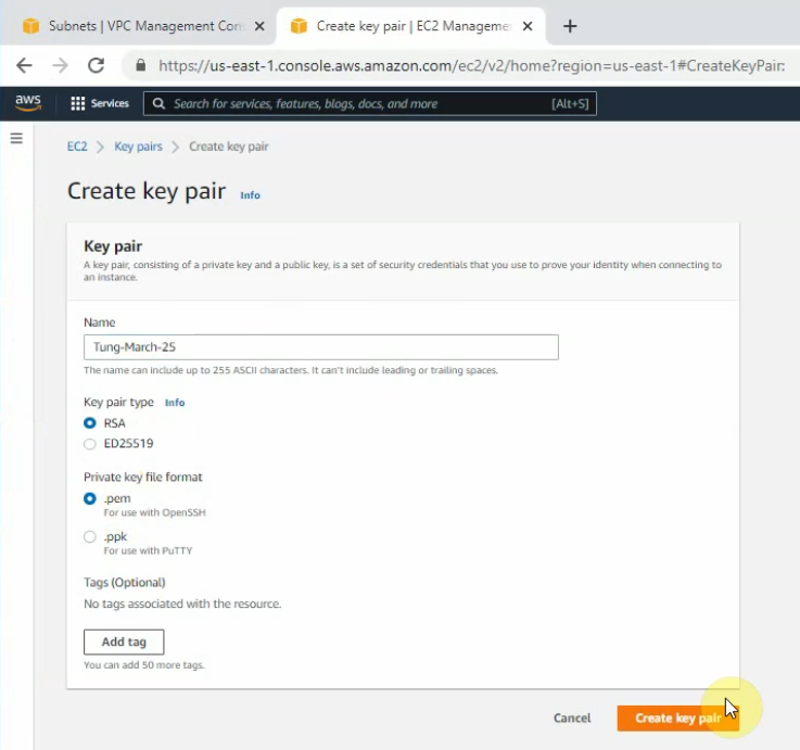
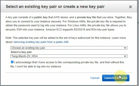
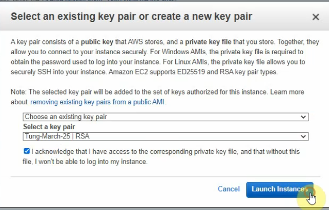
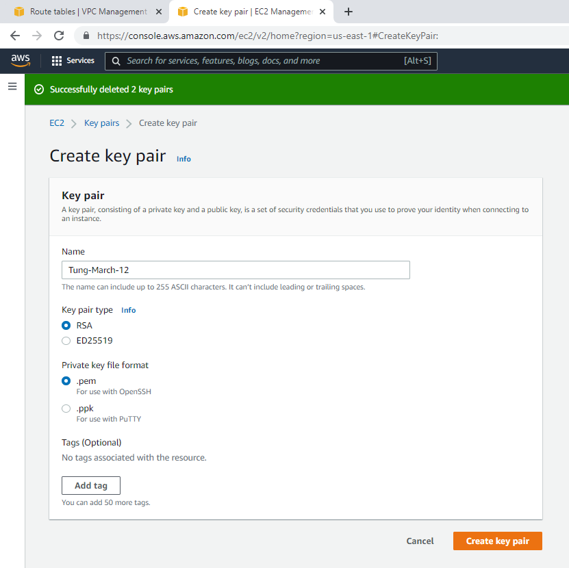
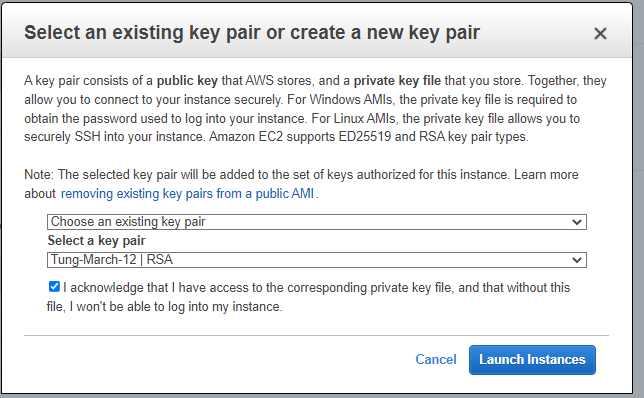
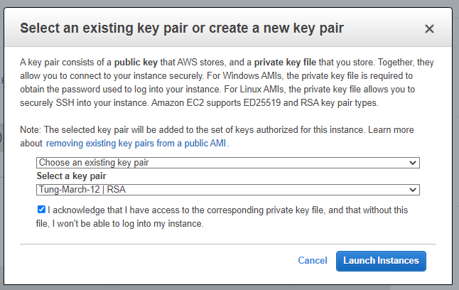
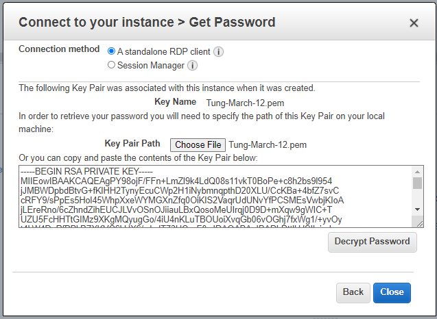
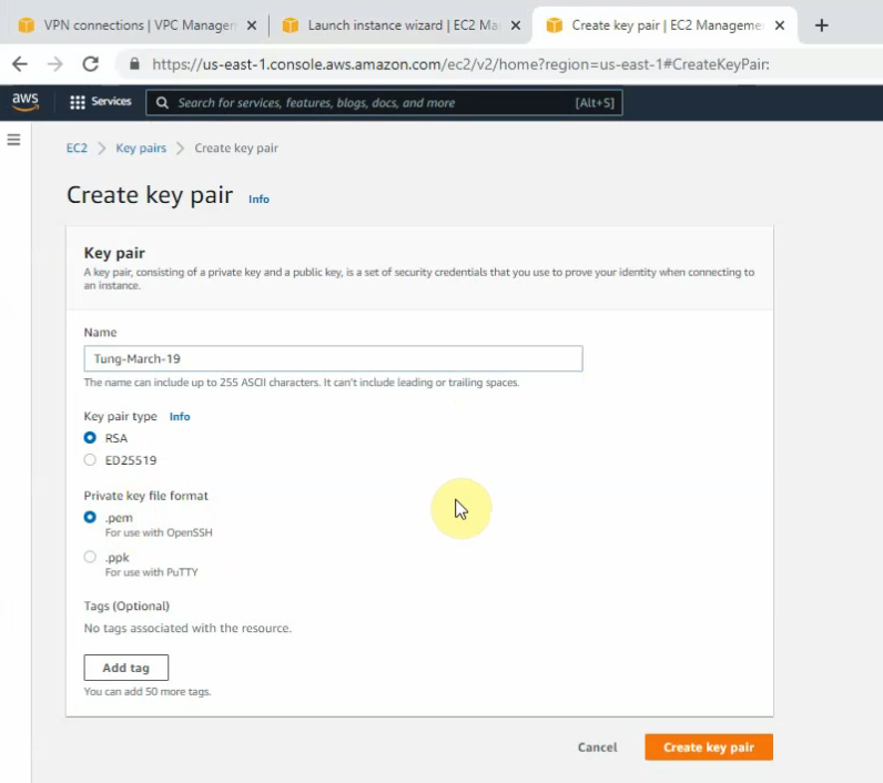
Create a new key pair on AWS.
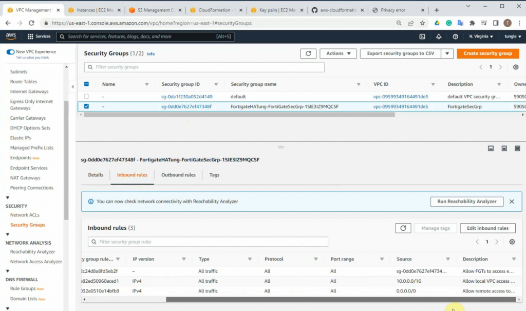
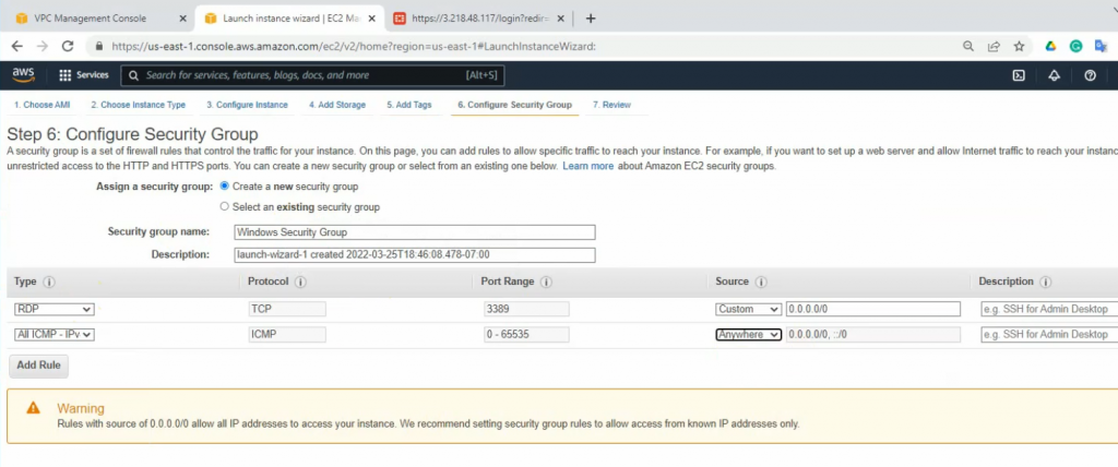
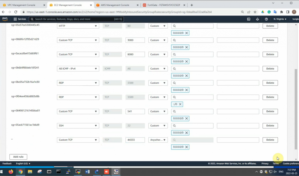
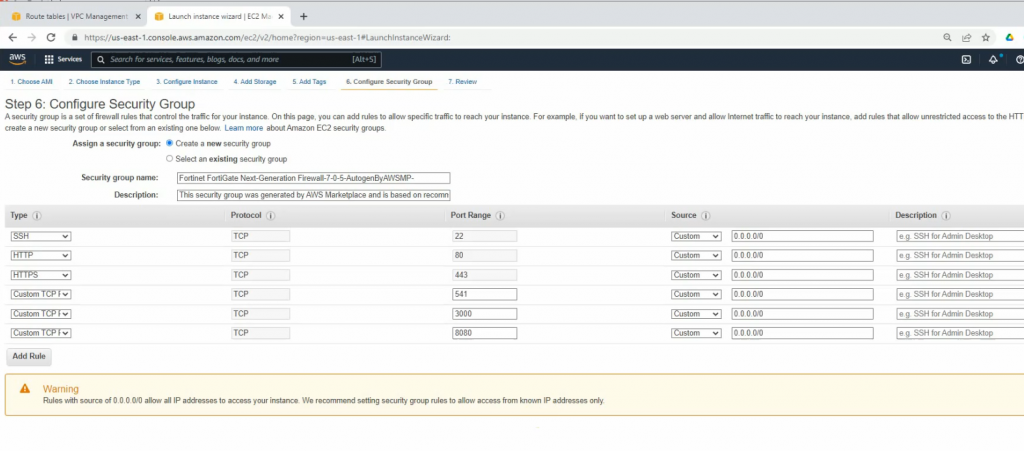
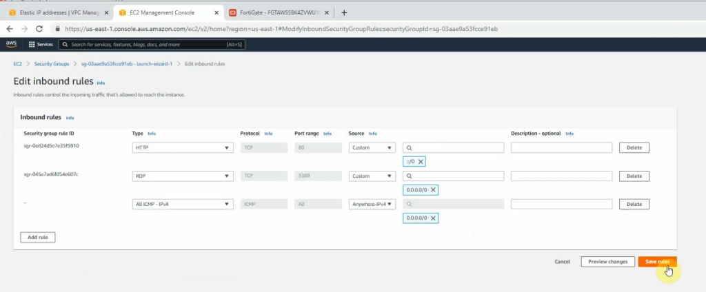
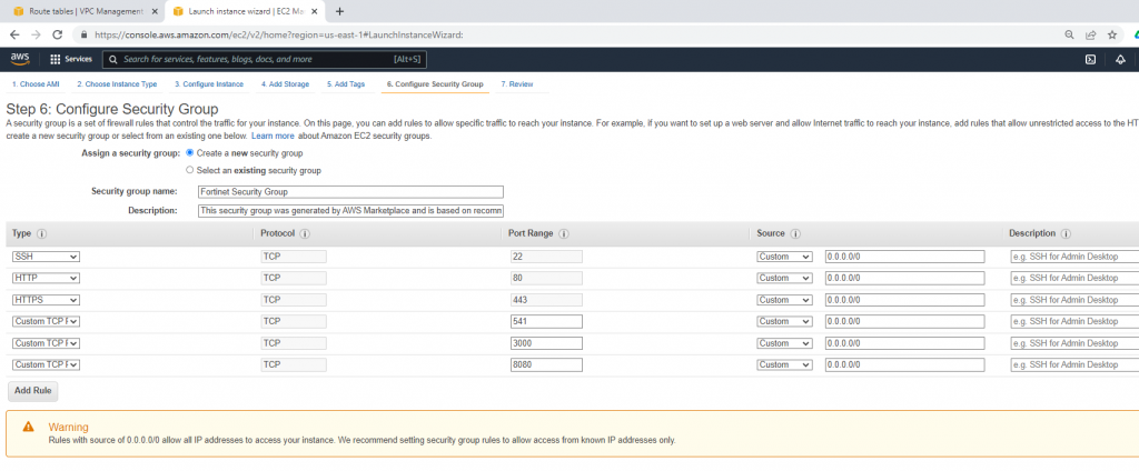
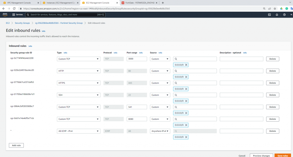
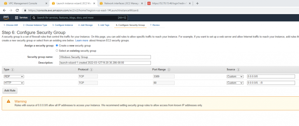
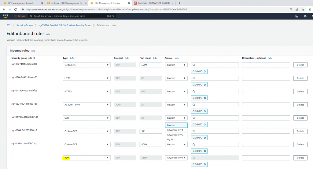
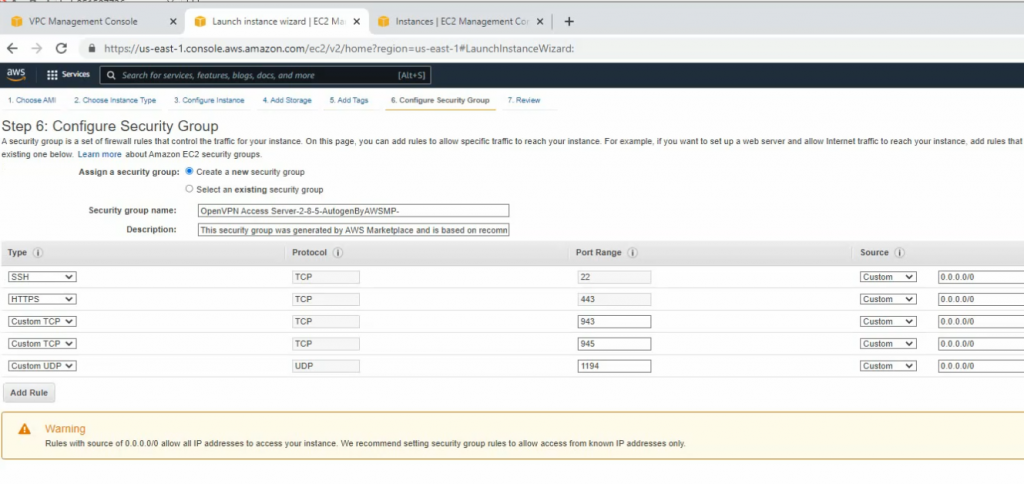
Allow HTTP, SSH, and ICMP on Security Group.
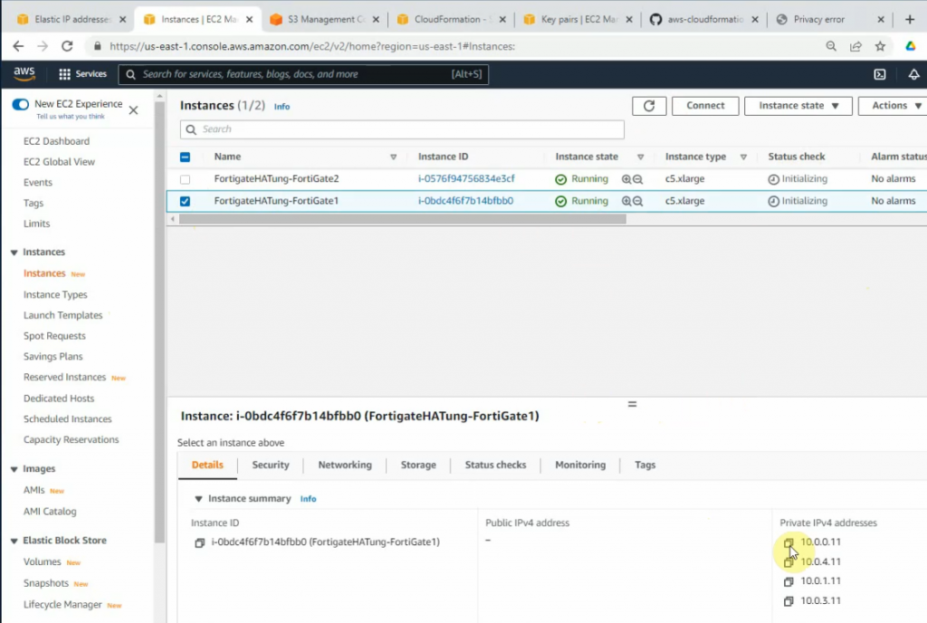
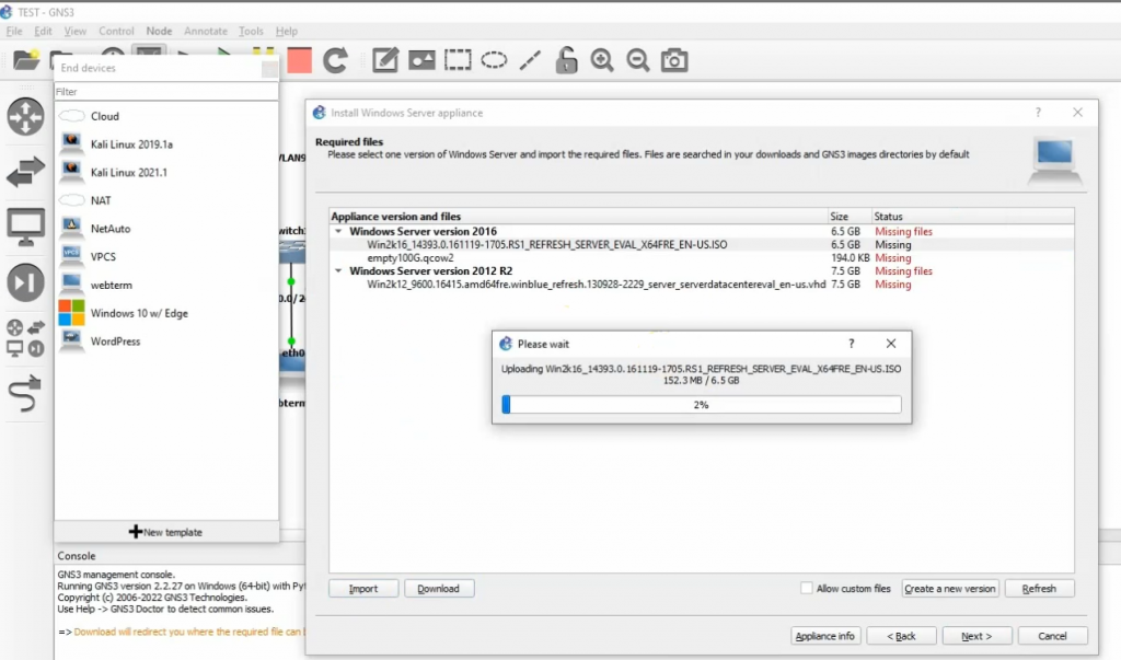
Back to GNS3, configure a new Windows 2016 server VM.
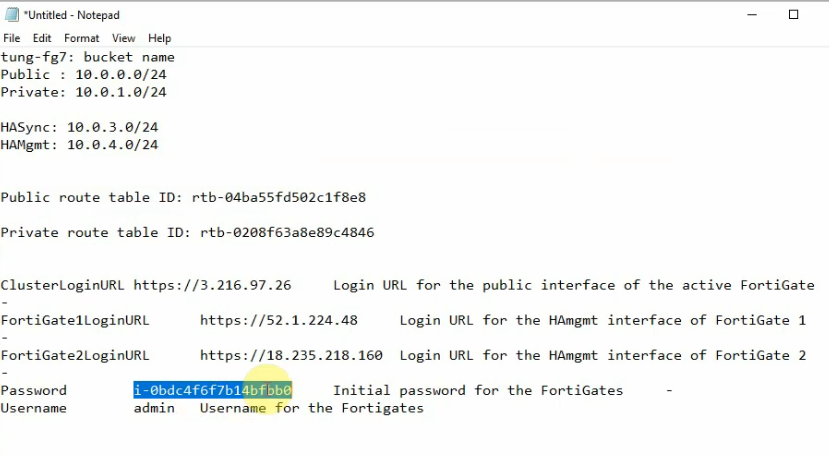
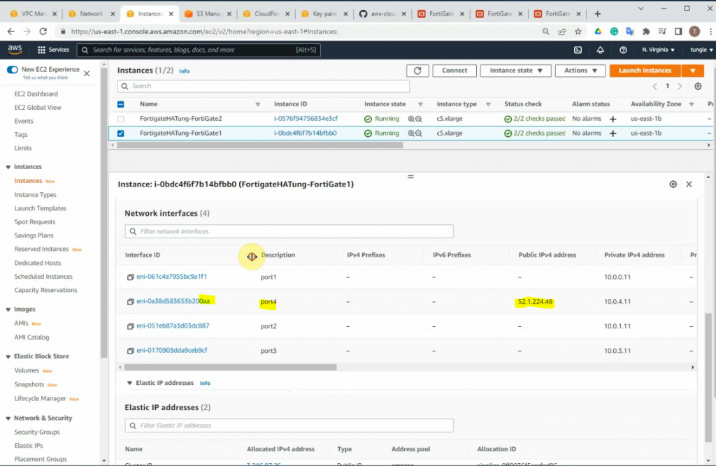
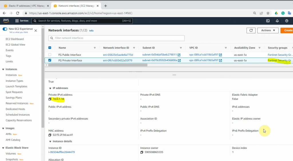
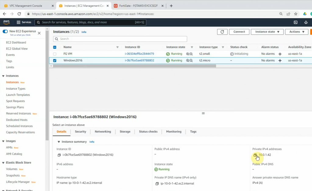
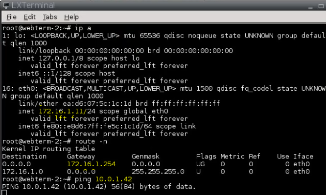
Takes notes of IP address of Linux instance on AWS.
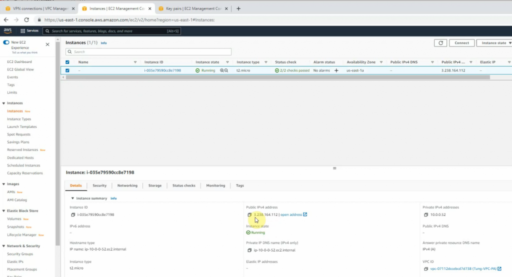
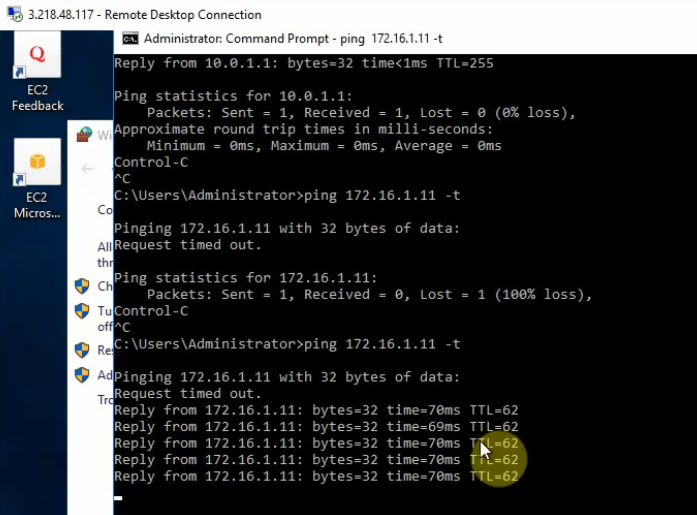
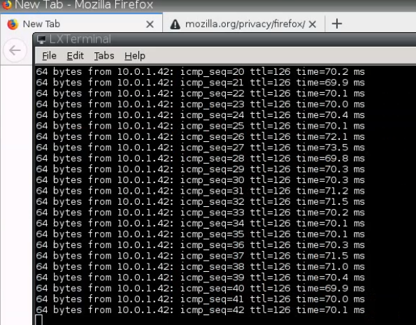
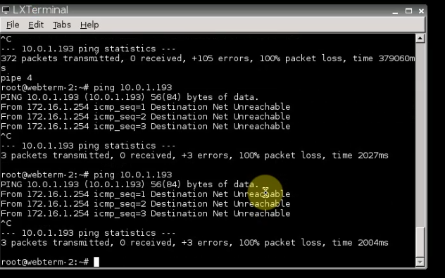
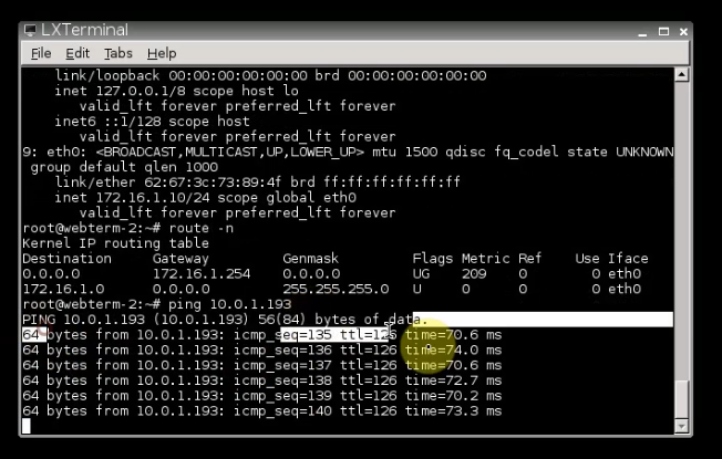
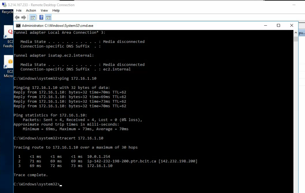
Ping the Linux instance on AWS LAN subnet from PA LAN subnet.
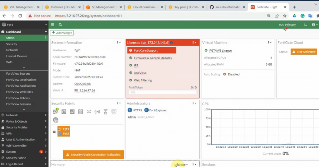
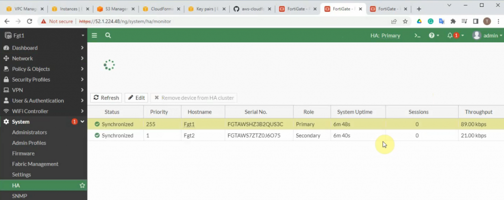
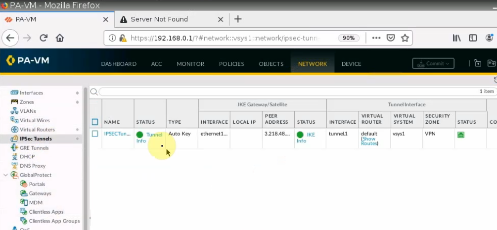
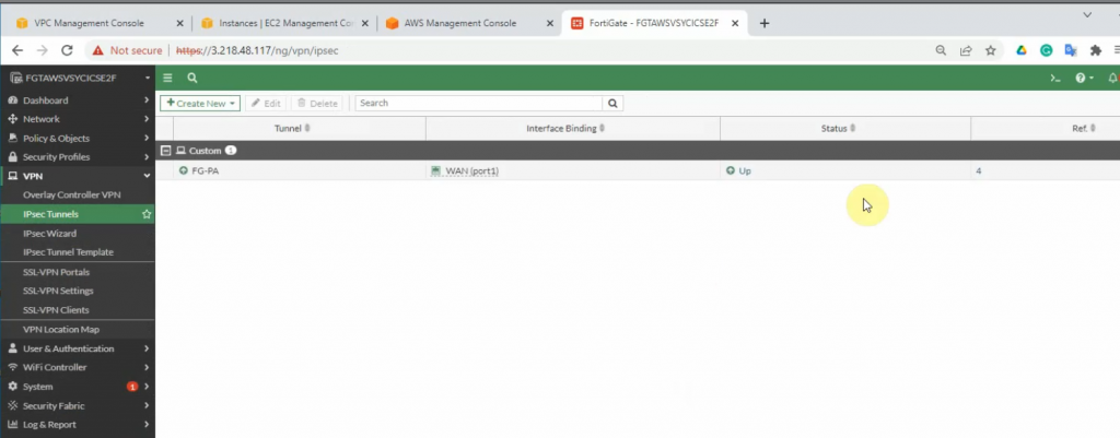
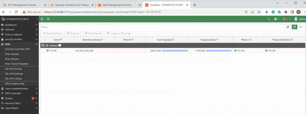
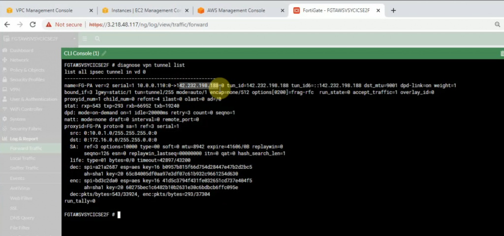
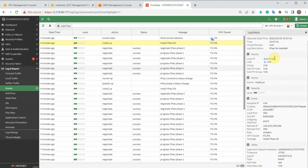
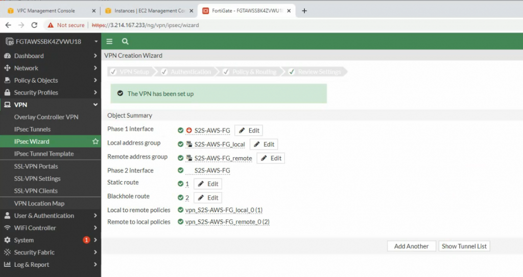
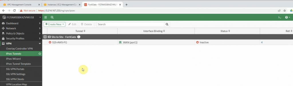
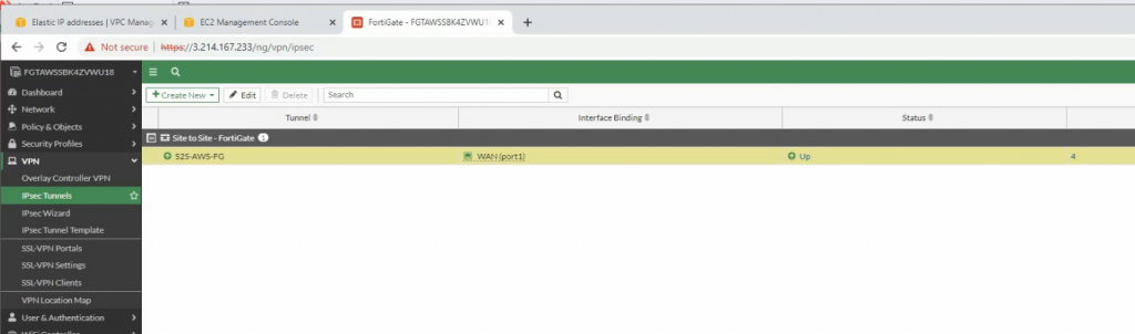
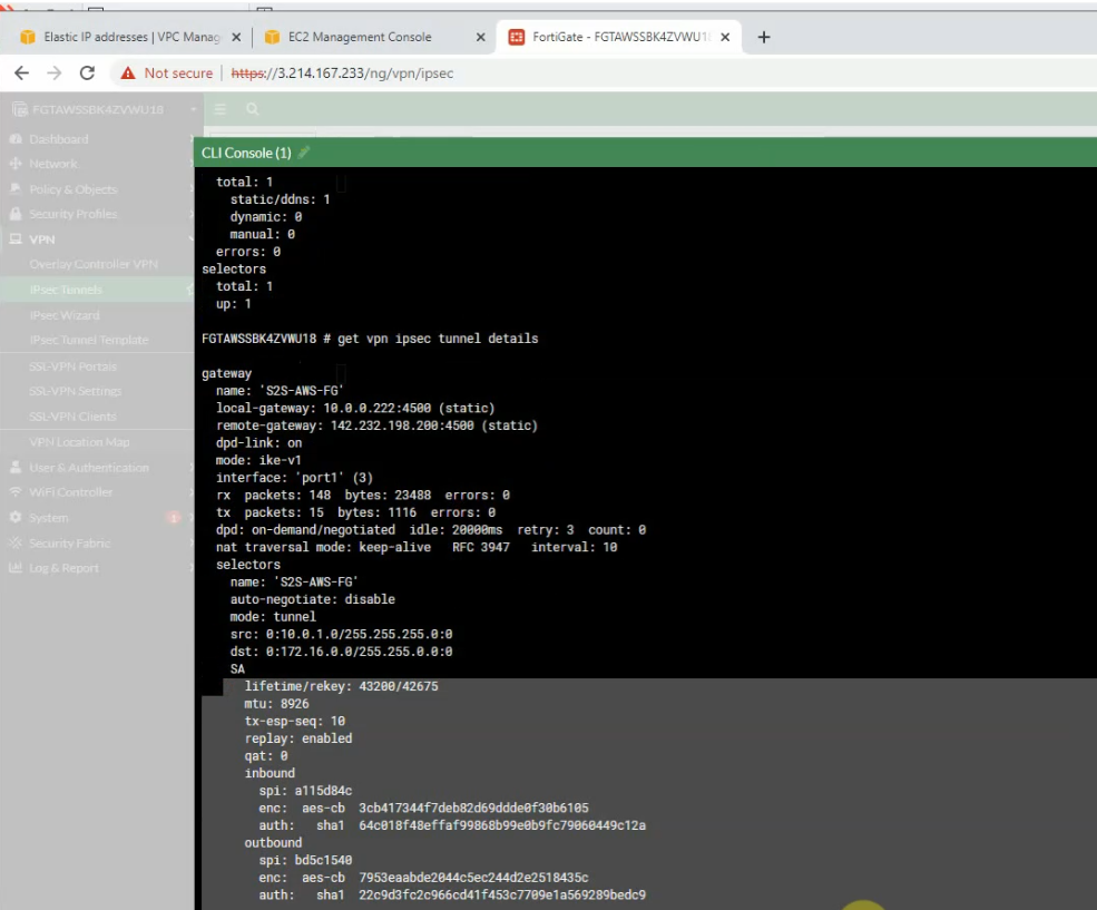
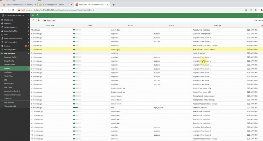
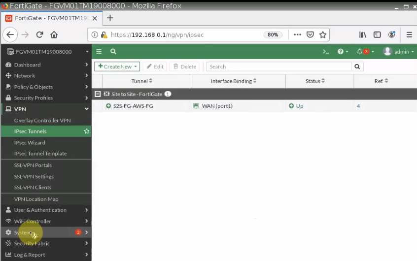
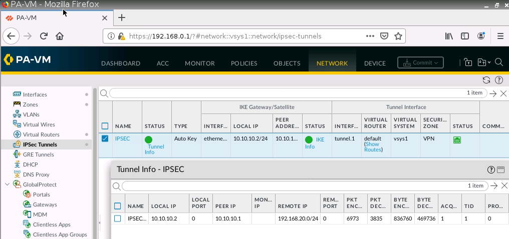
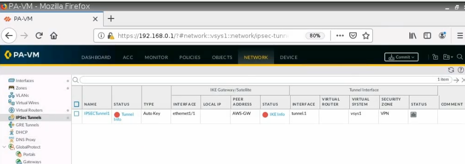
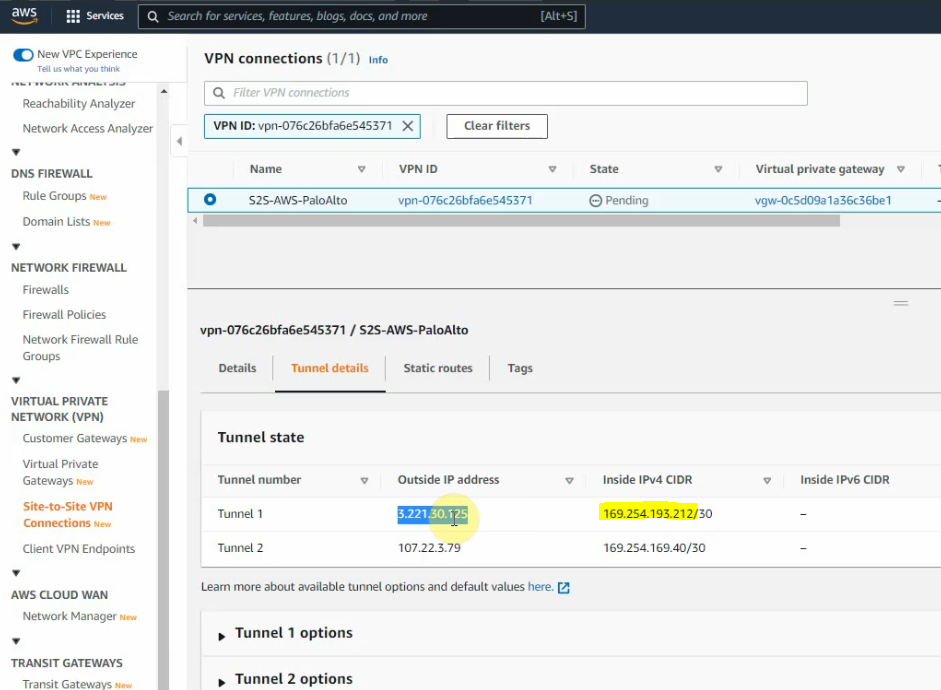
The tunnel is up on PA
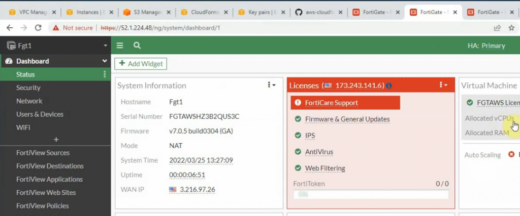
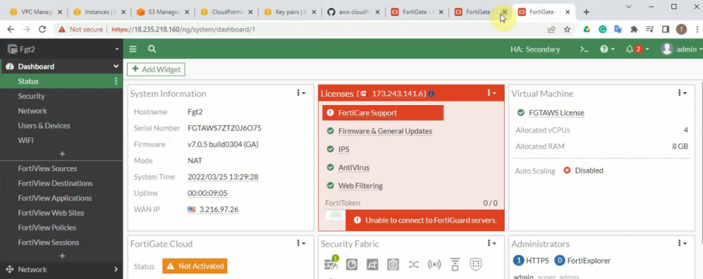
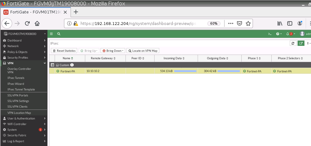
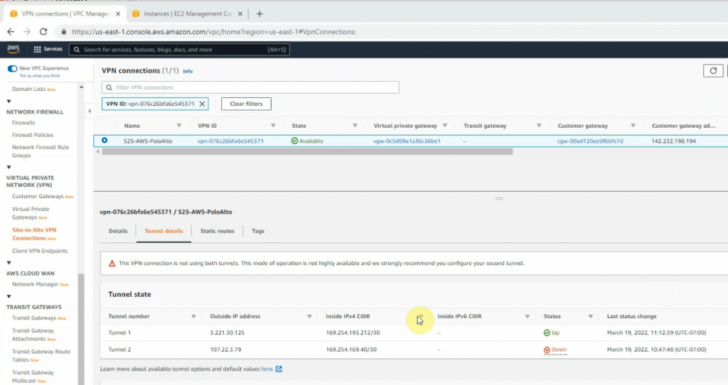
On AWS, the tunnel is up as well.
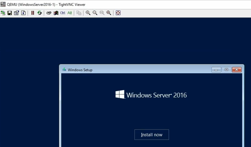
Configure Windows 2016 on GNS3.
Install Windows 2016.
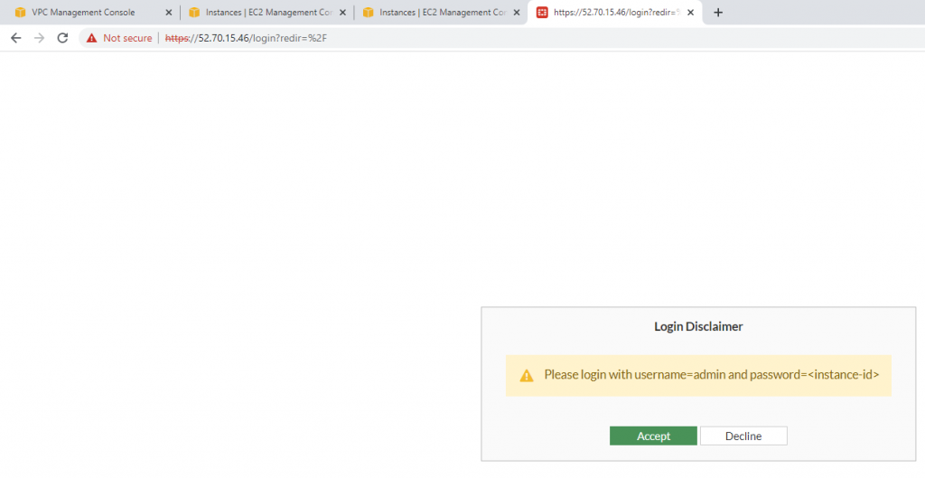
On Kali, access SSH to Linux VM instance on AWS>
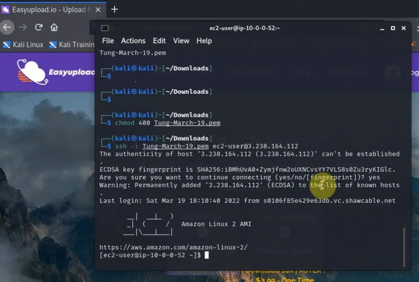
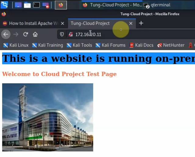
Website on-prem.
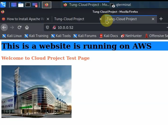
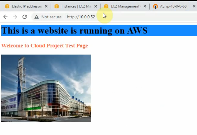
Website on AWS.
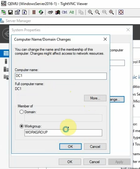
Change computer name to DC1 and promote it to a domain controller.
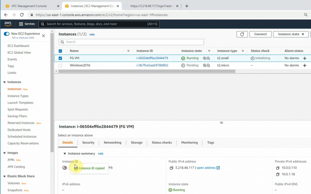
Create a new Windows VM on AWS.
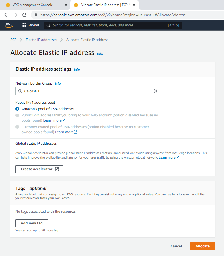
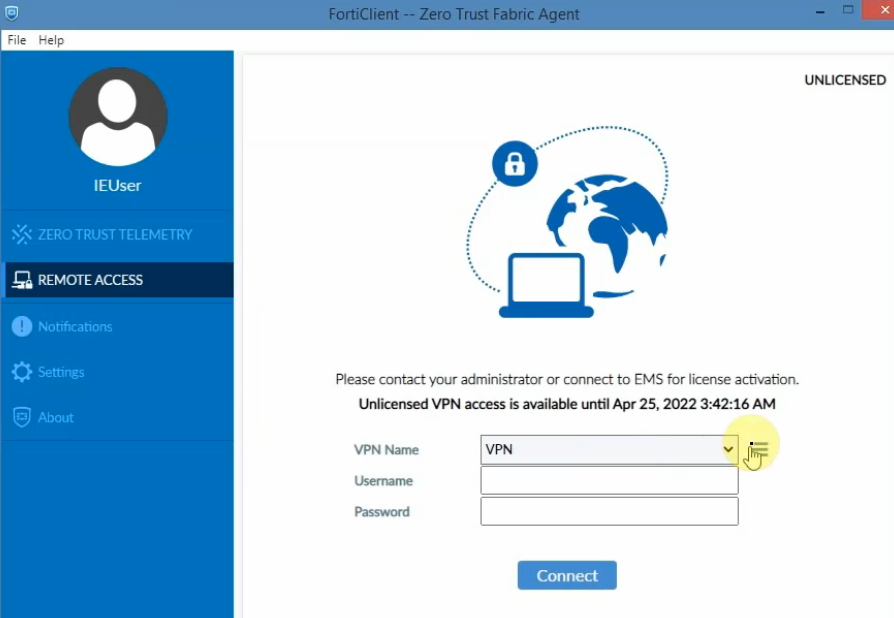
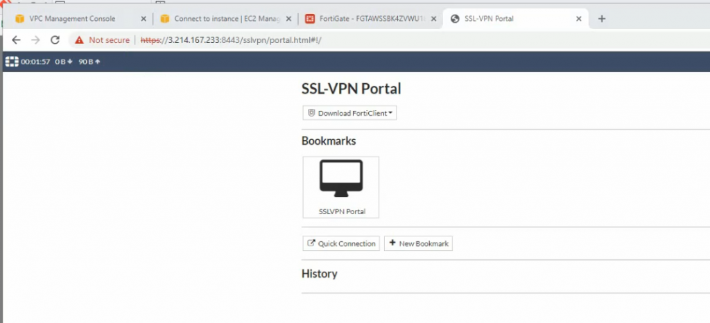
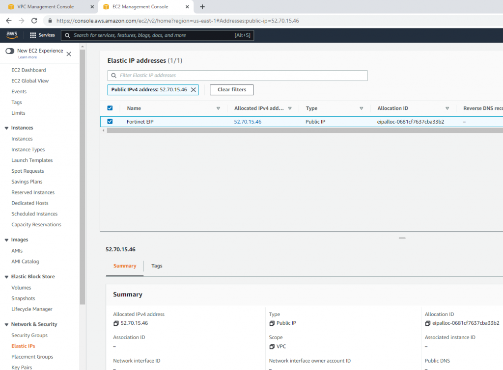
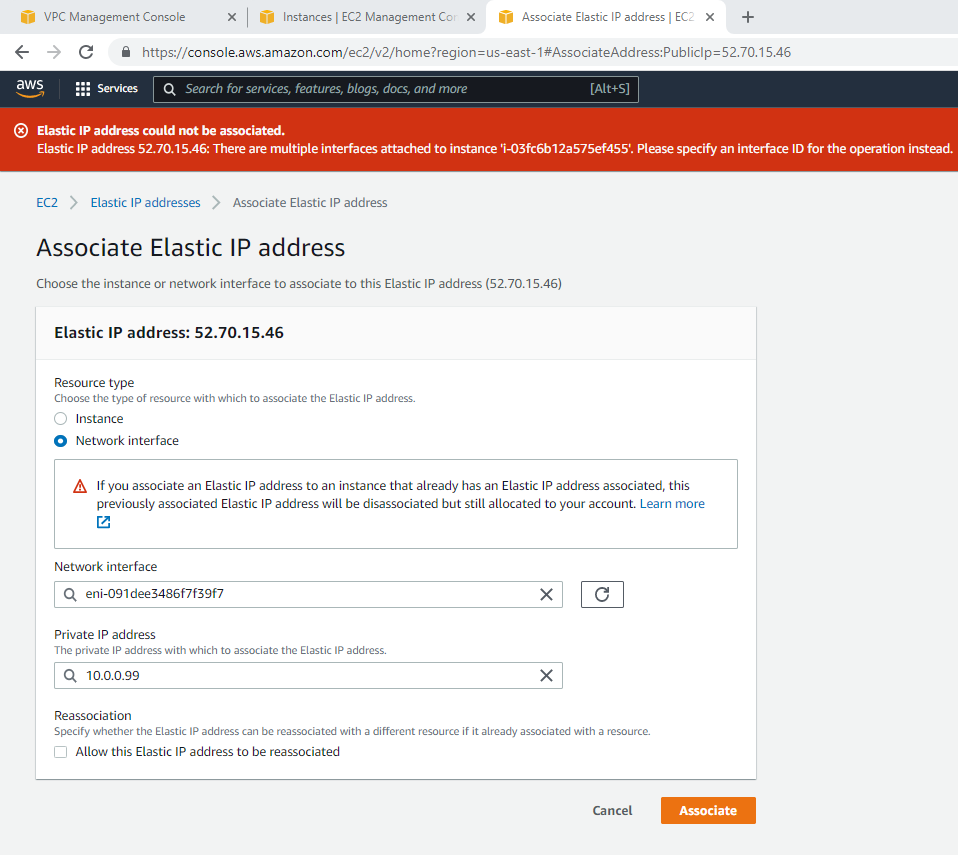
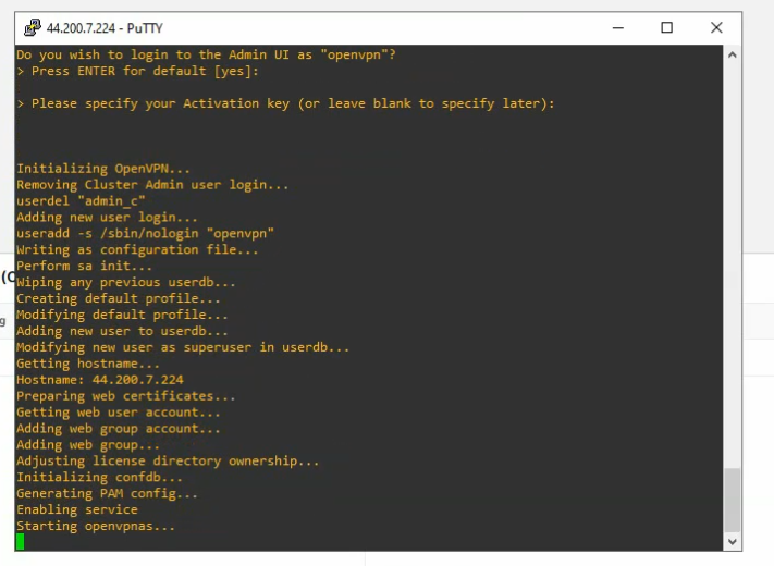
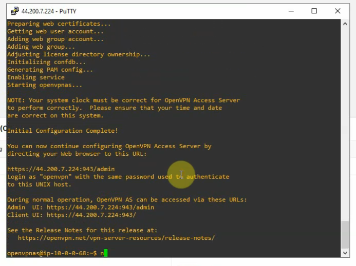
Create a new OpenVPN server instance on AWS.
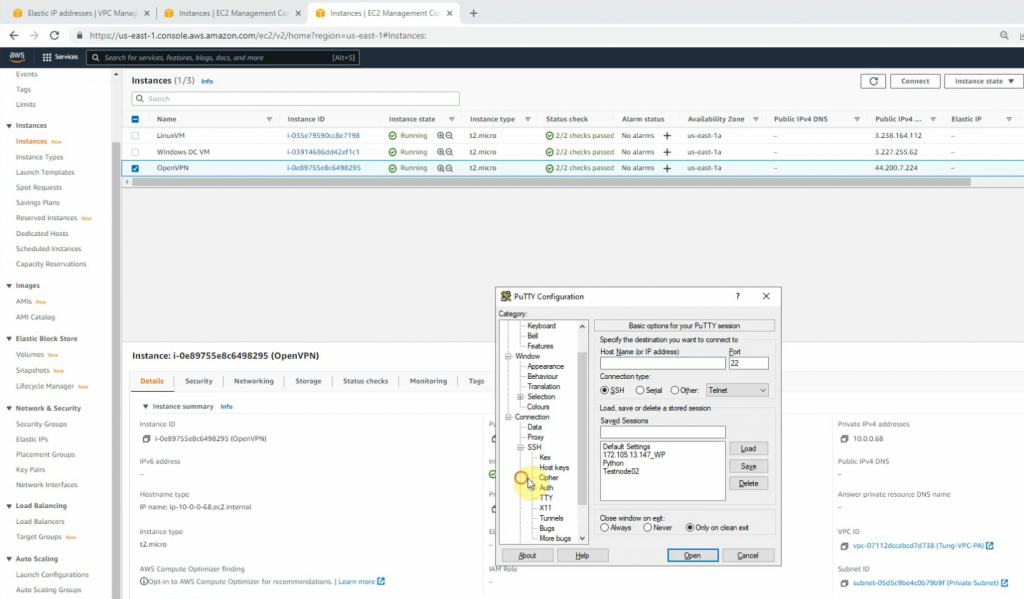
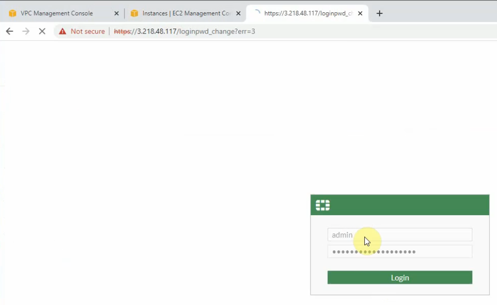
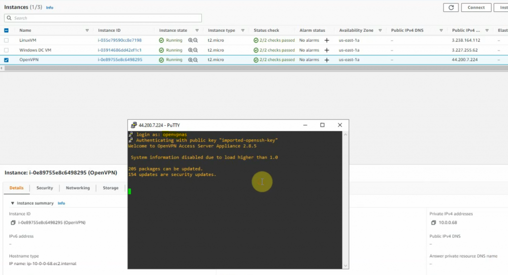
Access the OpenVPN server via SSH. Use openvpnas as a user to log in.
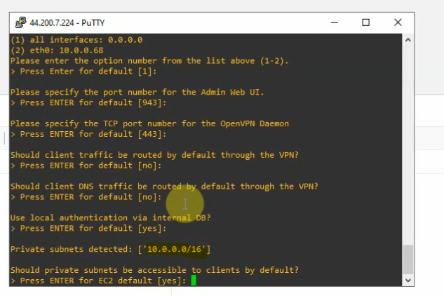
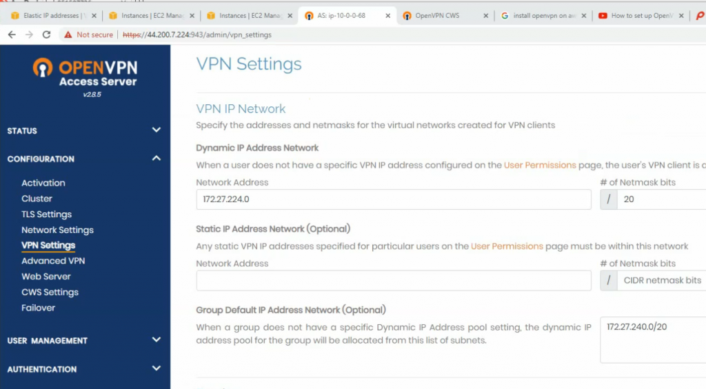
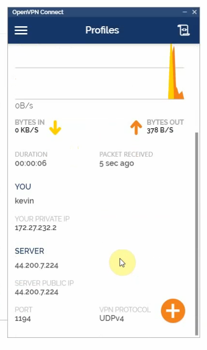
Check the private subnet on OpenVPN is matching with the private subnet on AWS.
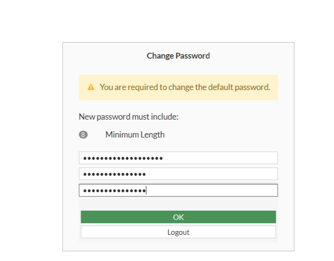
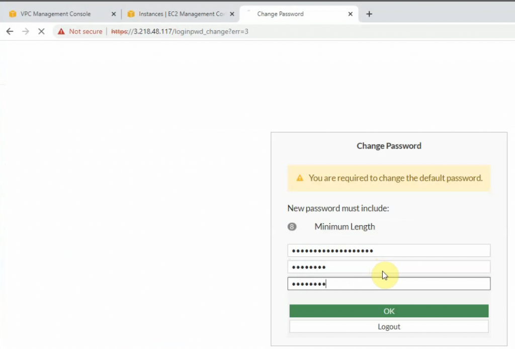
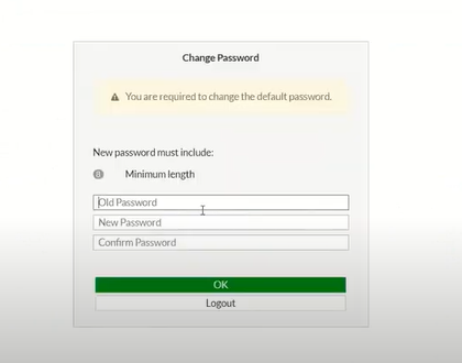
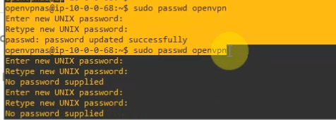
Change the password of openvpn.
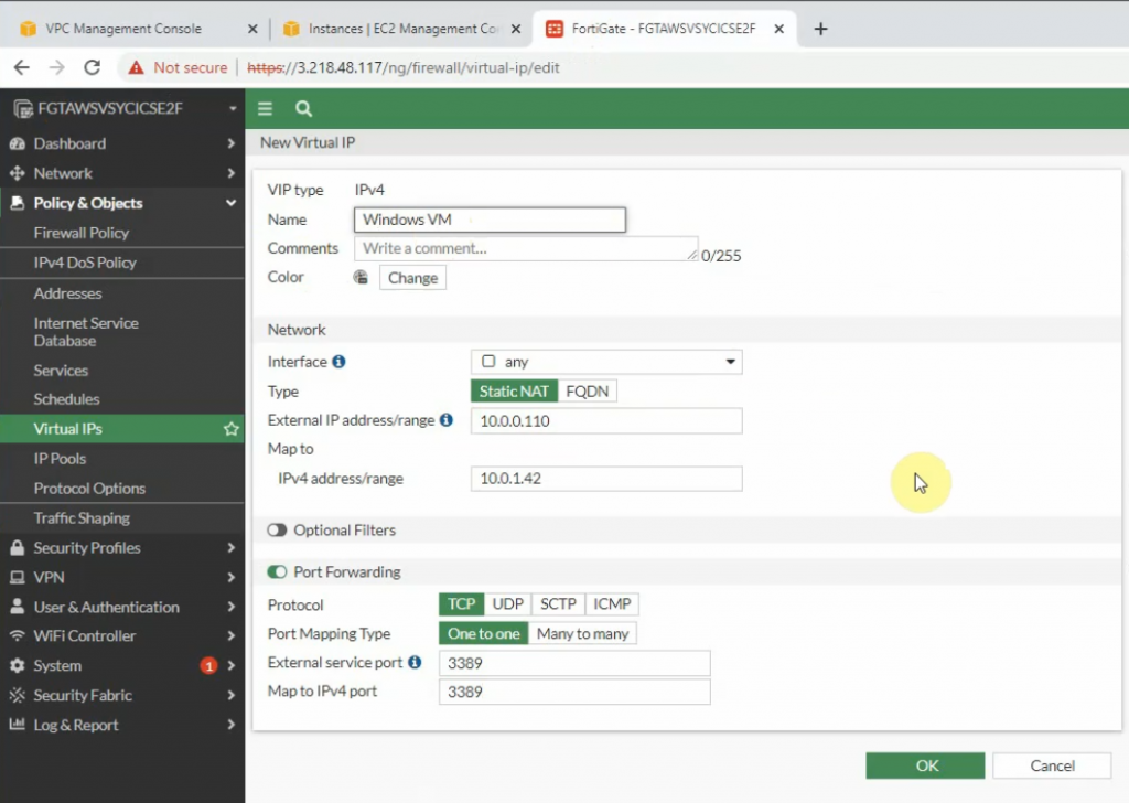
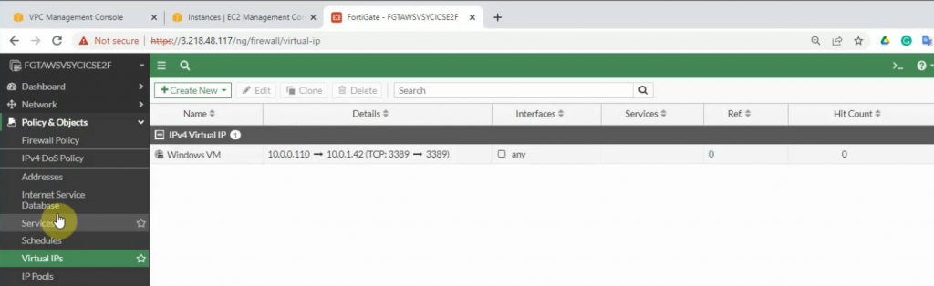
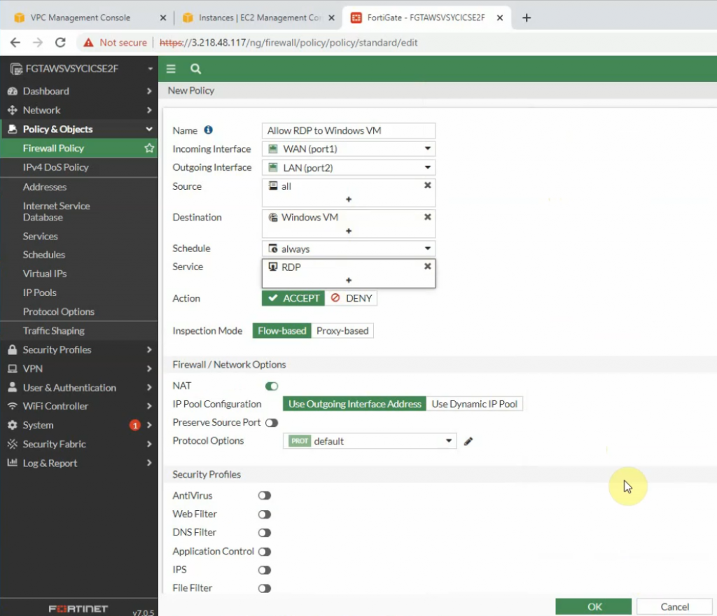
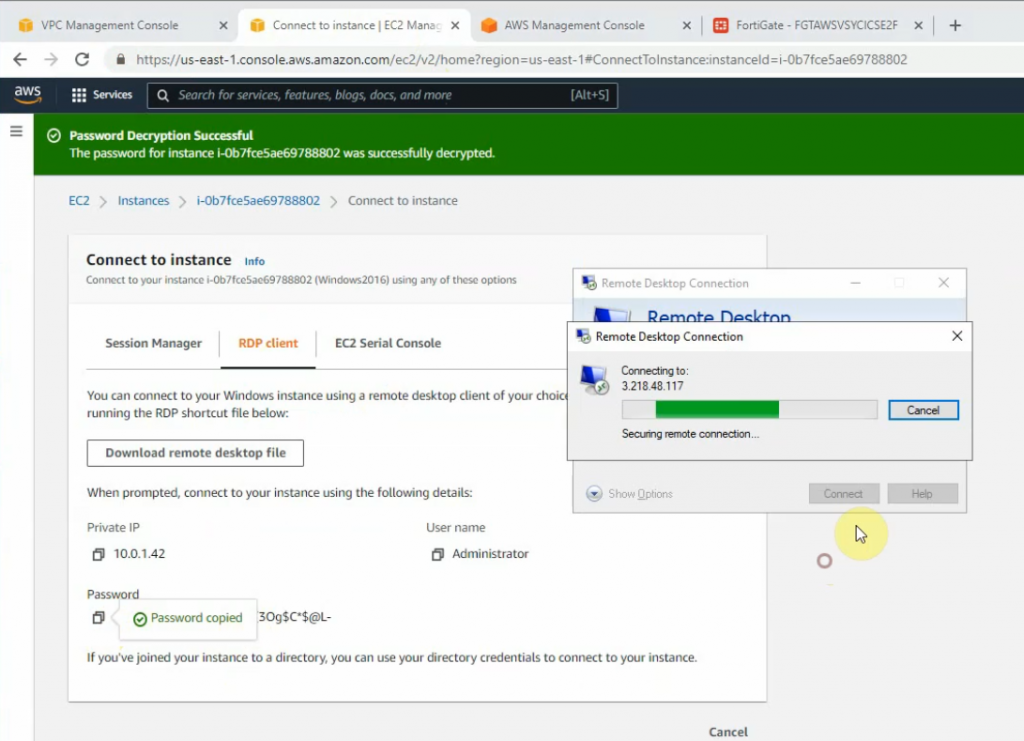
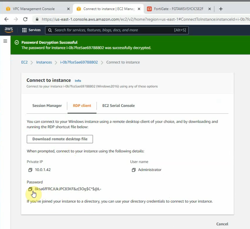
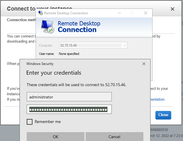
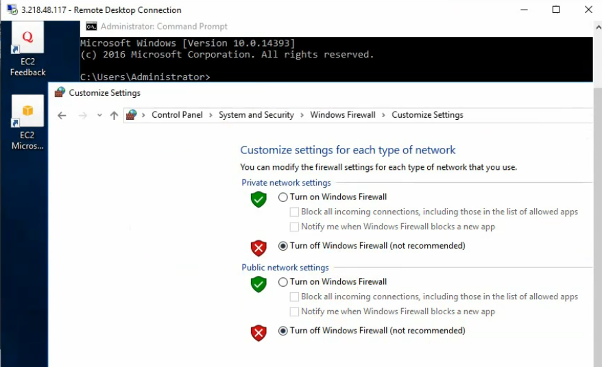
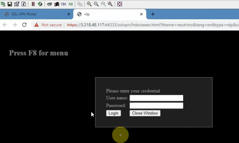
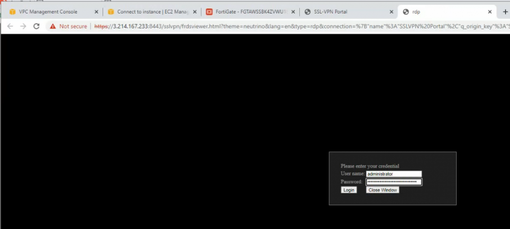
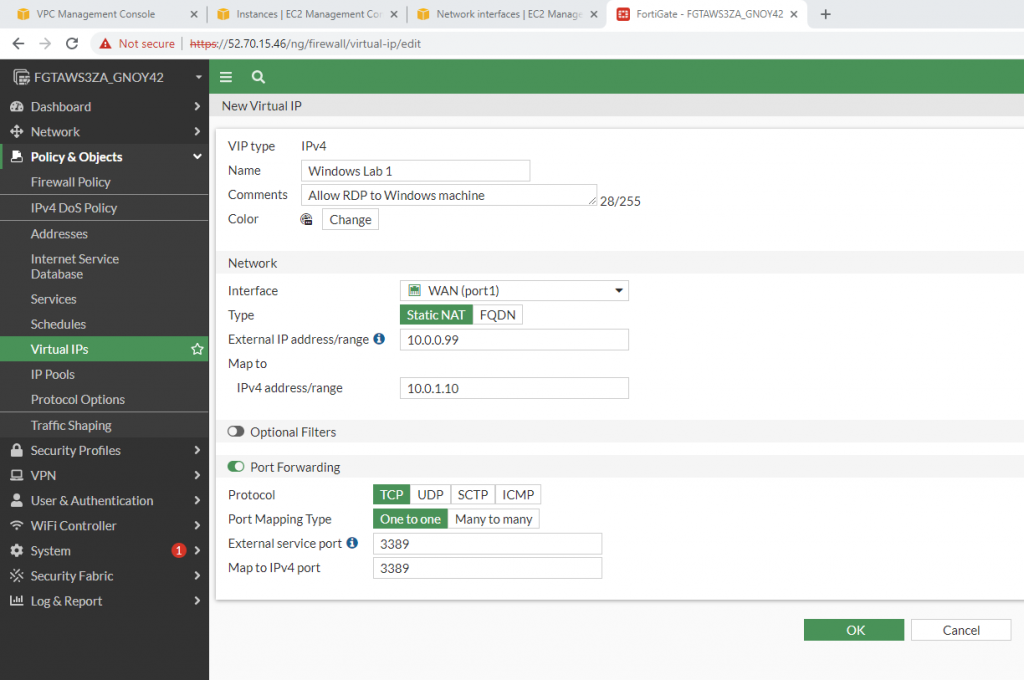
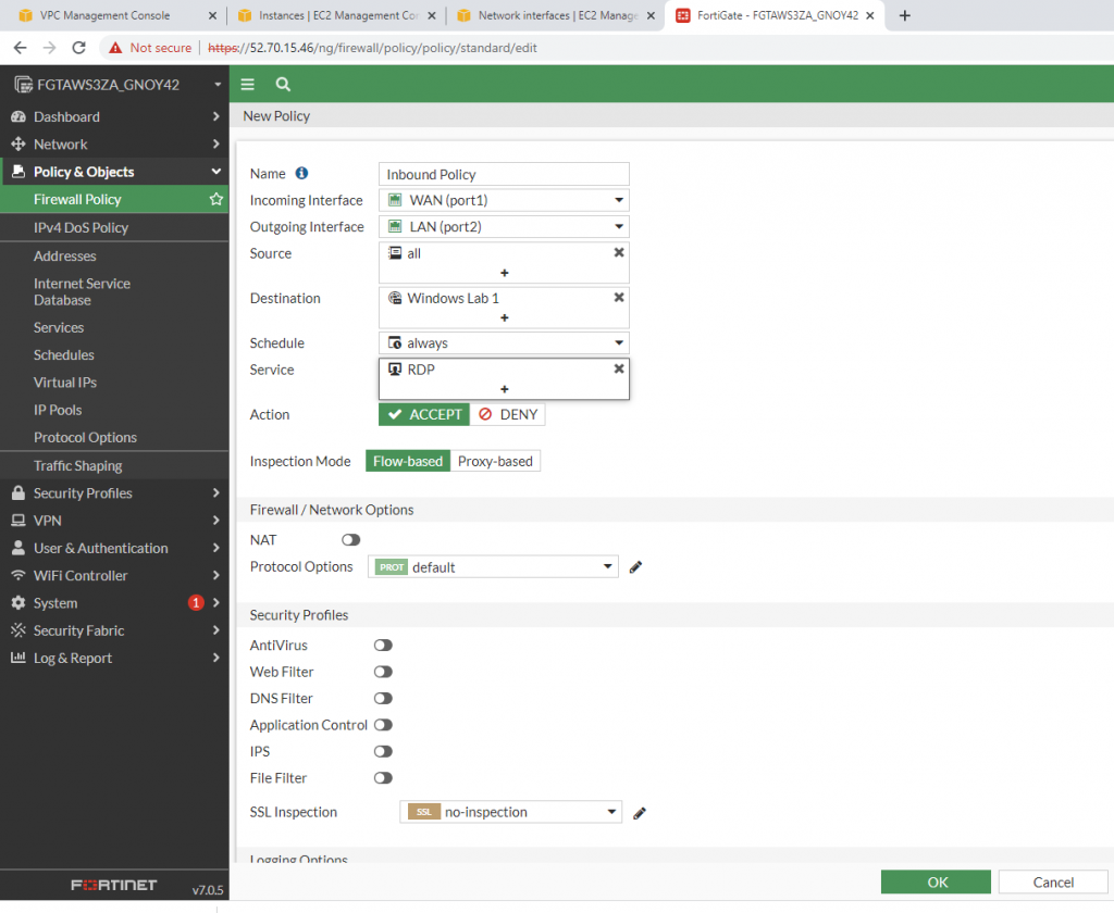
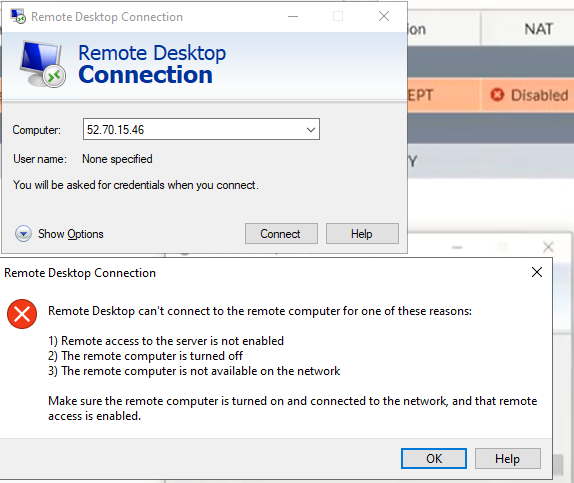
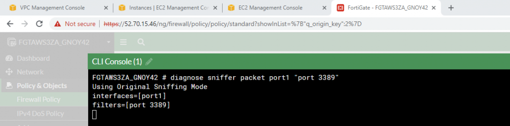
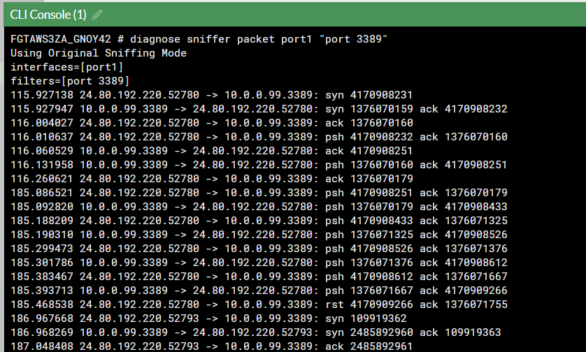
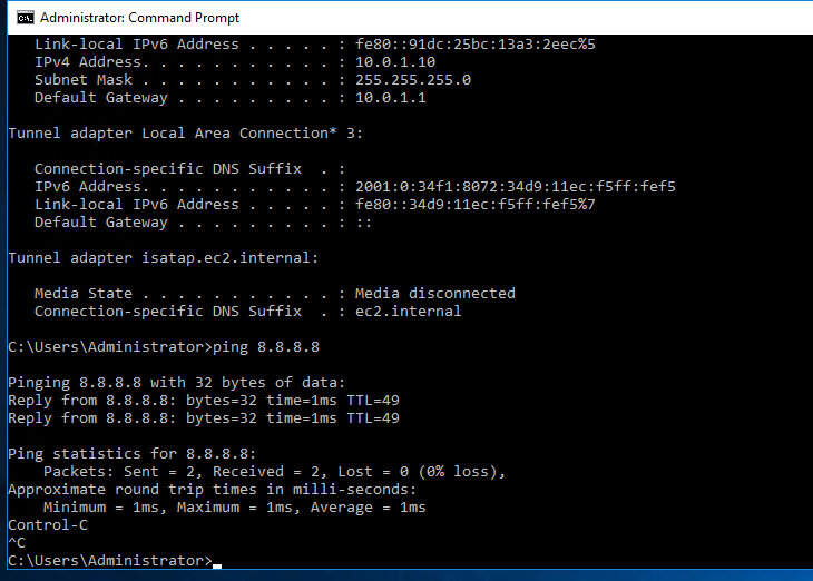
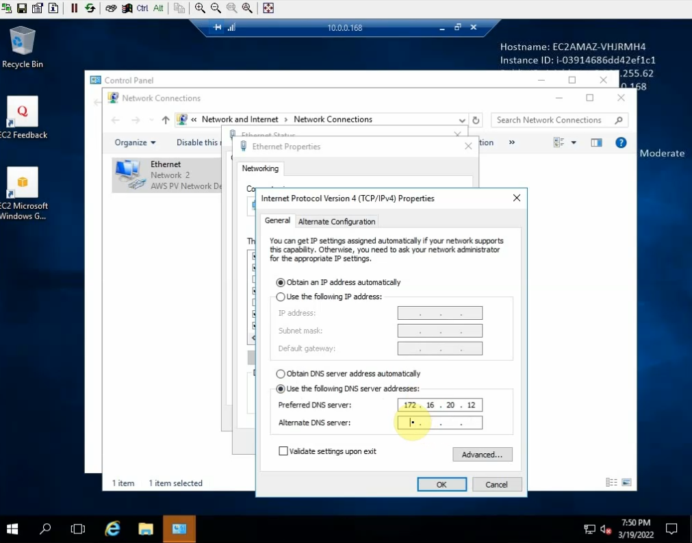
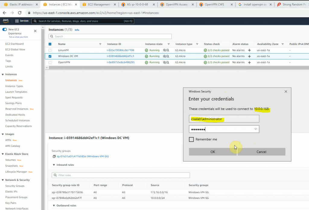
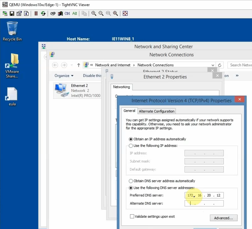
From Windows 2016 VM on GNS3, access RDP to Windows instance on AWS. Change DNS setting to DC1 on-prem.
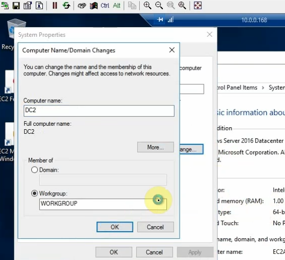
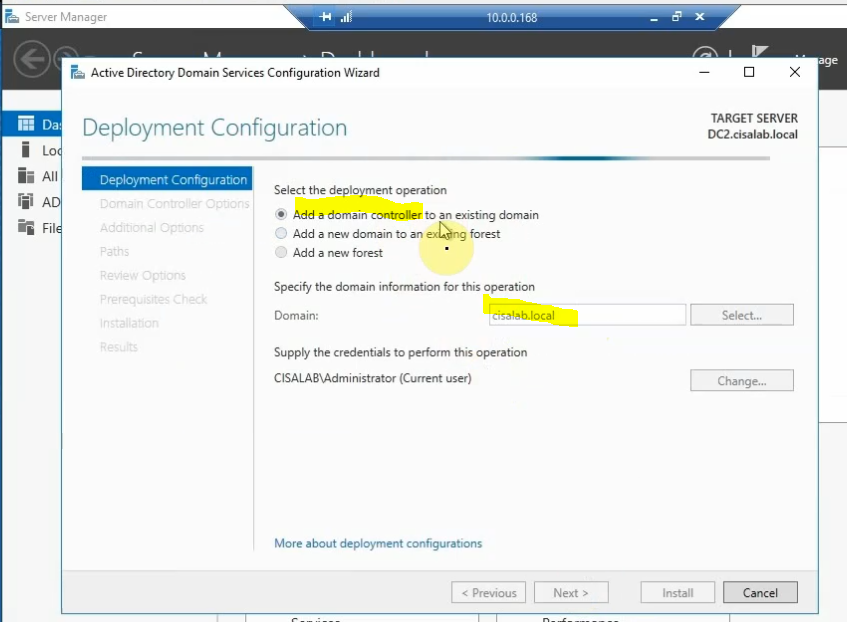
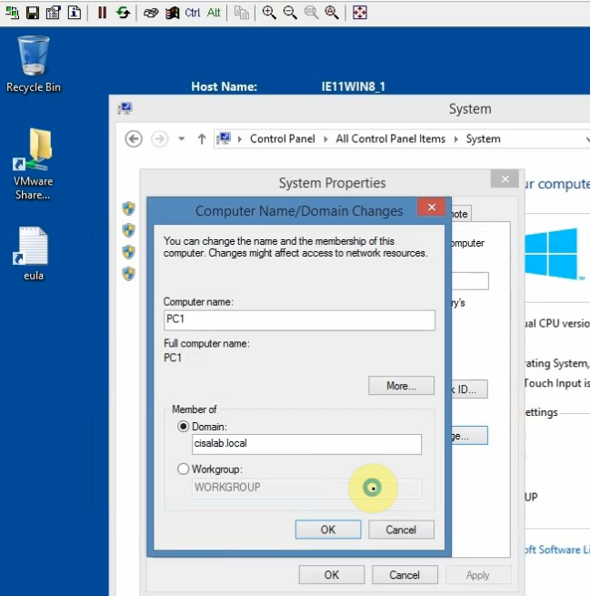
Join the machine to domain on-prem and promote it to become additional domain controller.
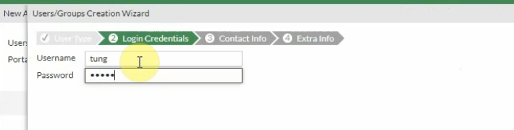
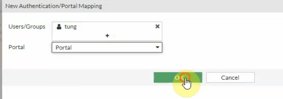
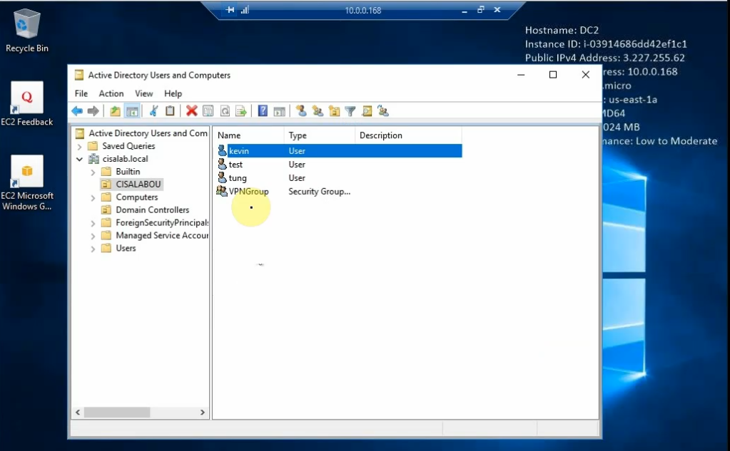
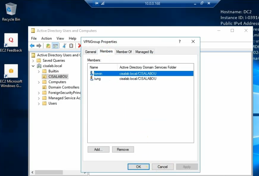
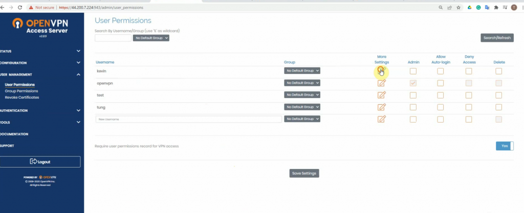
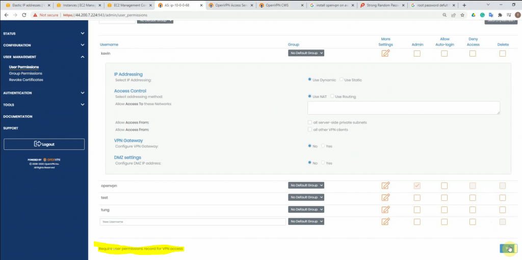
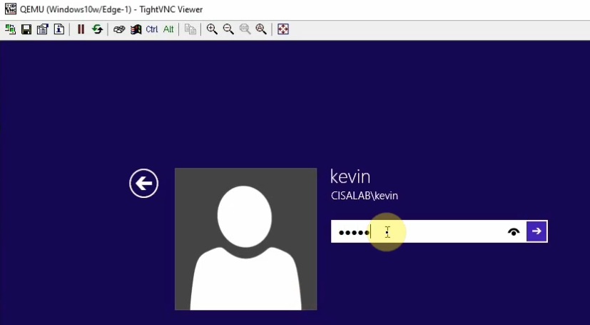
Create a couple of users to test: tung, kevin, test on domain controllers.
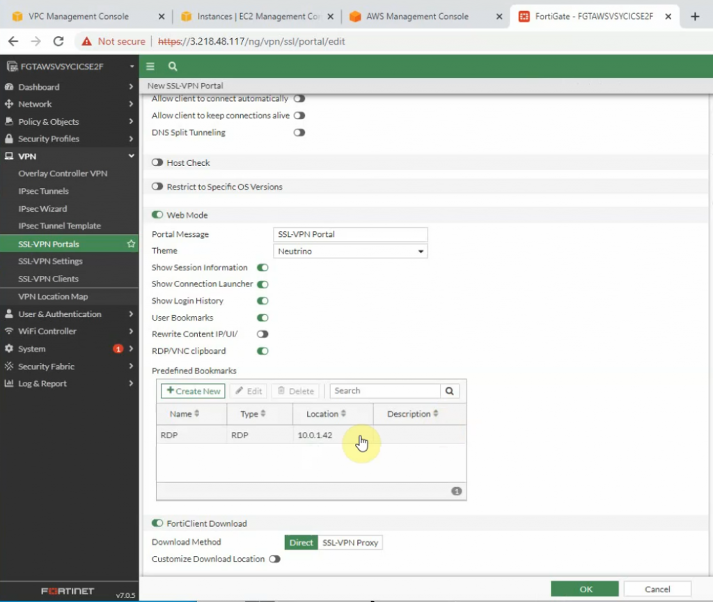
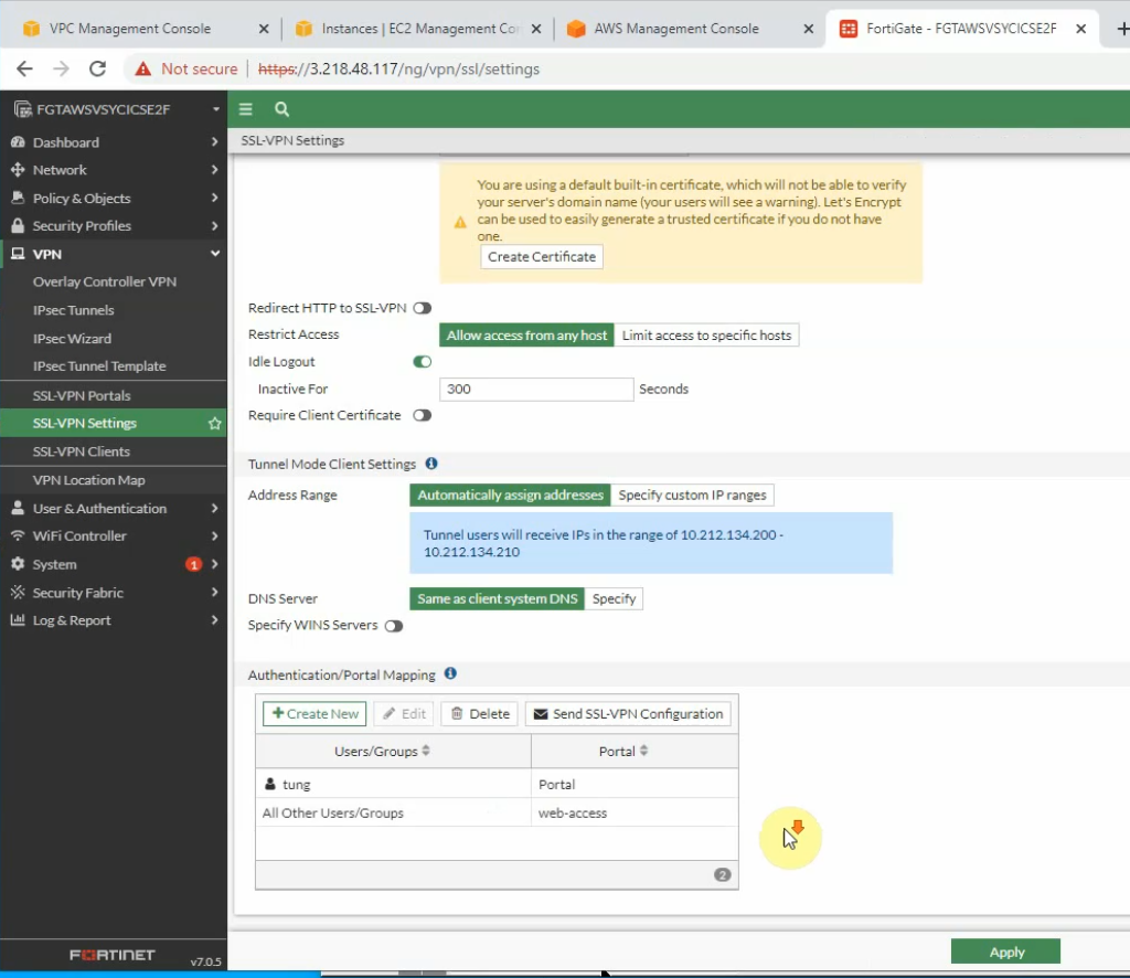
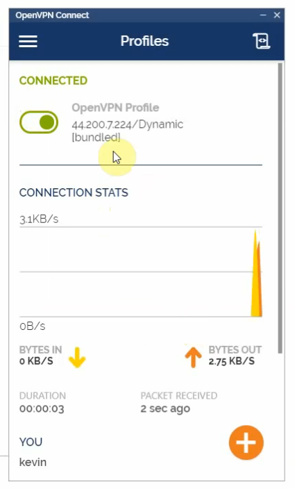
On OpenVPN.
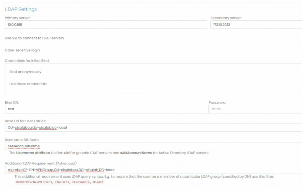
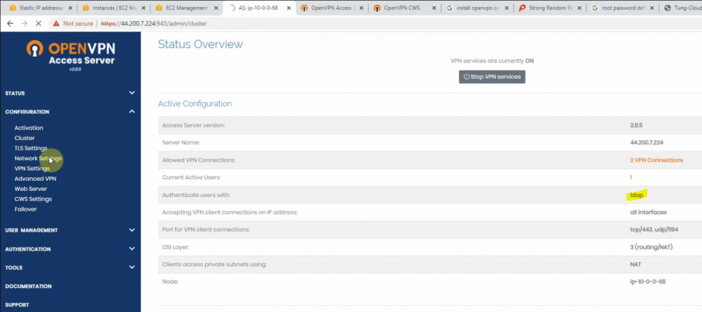
Change the setting to authenticate the OpenVPN tunnel via LDAP. We use both LDAP servers on AWS and on-prem.
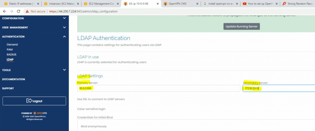
Configure LDAP settings to query the corresponding information on domain controllers.
Access to OpenVPN mgmt interface.
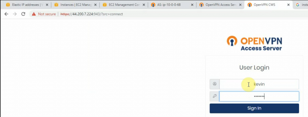
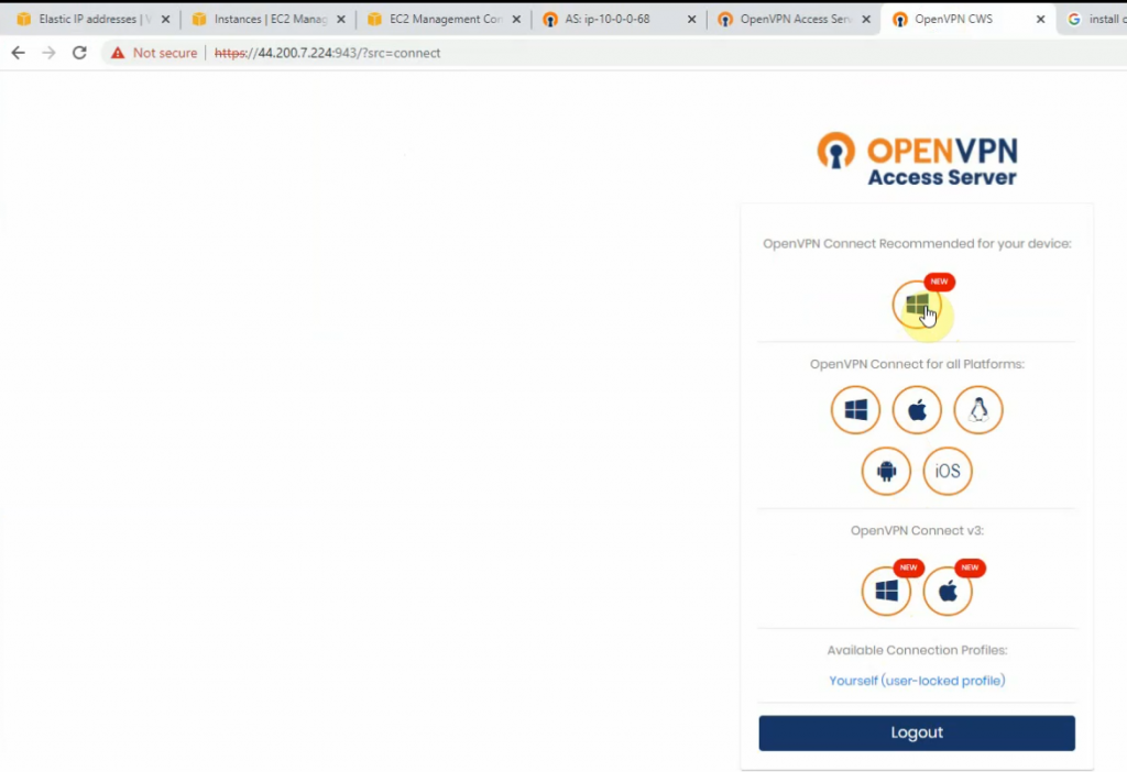
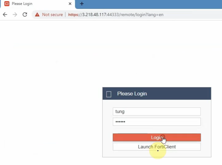
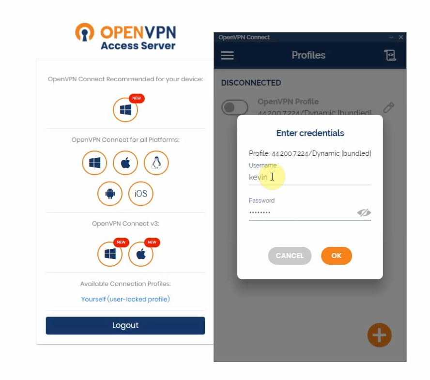
Using a kevin user to log in.
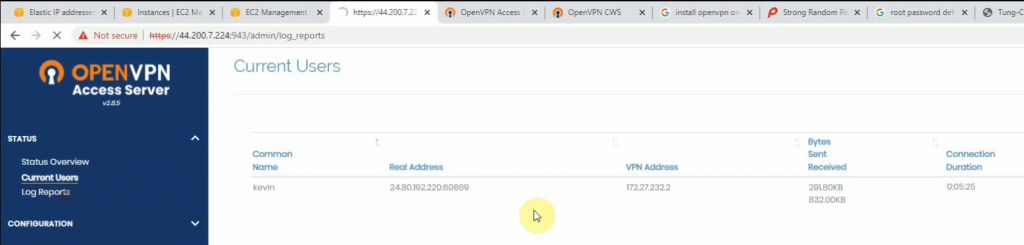
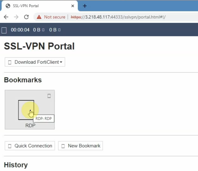
Access a web server on a private subnet on AWS.
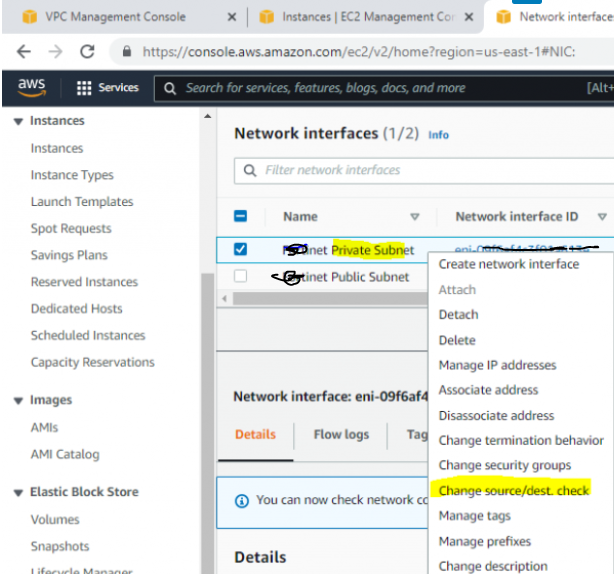
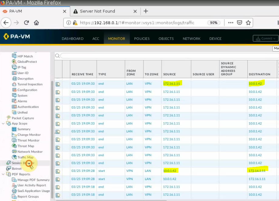
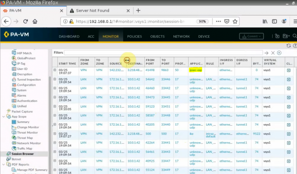
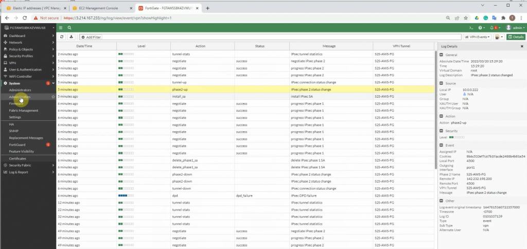
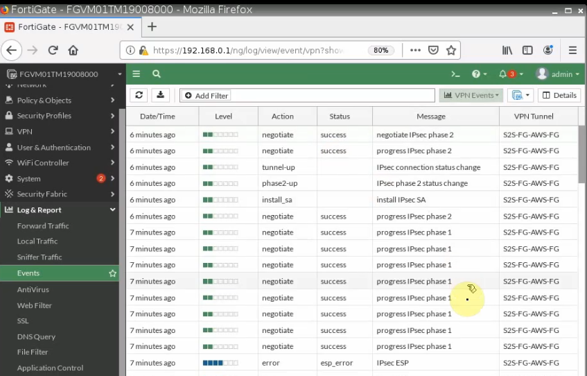
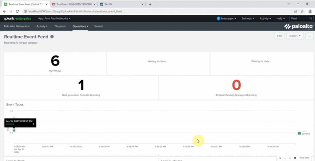
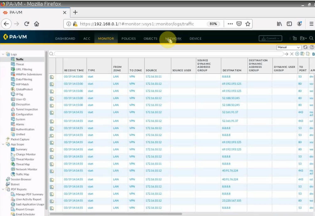
Monitor Security traffic on PA.
Join Windows 10 to the domain.
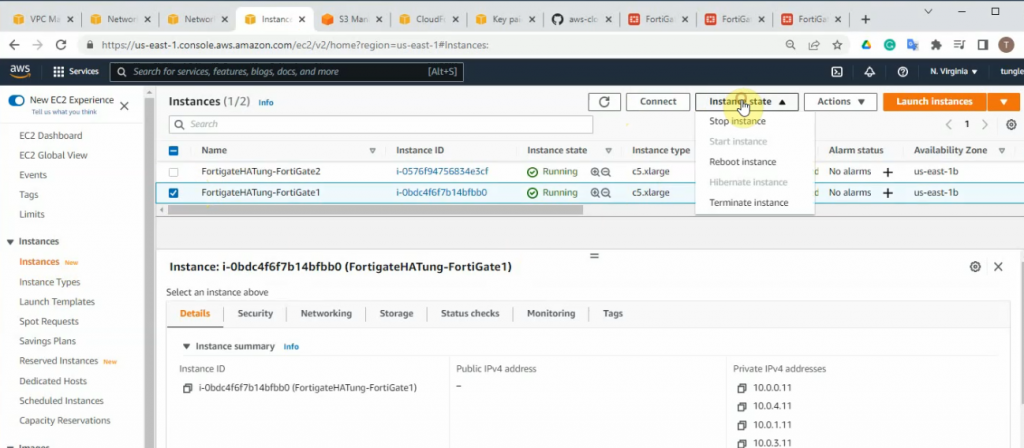
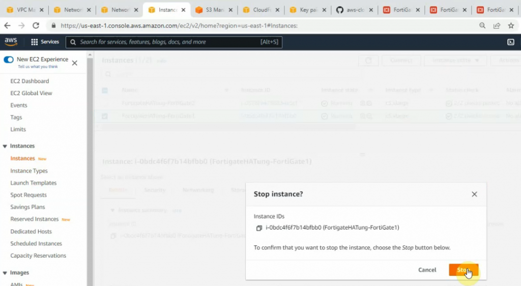
Disconnect interface from DC1 to SW2 to simulate migrating servers to AWS cloud.
Windows 10 is still accessible to the domain on DC2 on AWS.
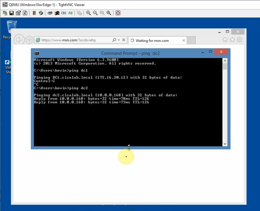
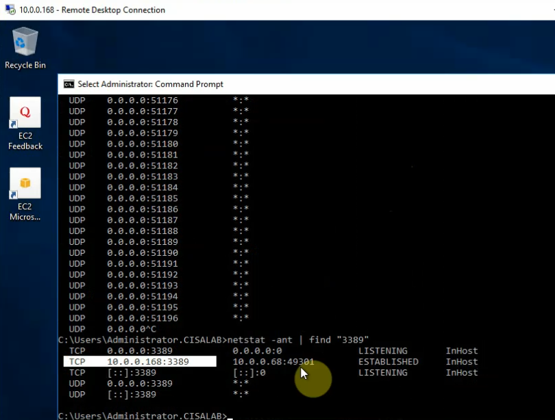
Access RDP to DC2 and a web server on AWS.
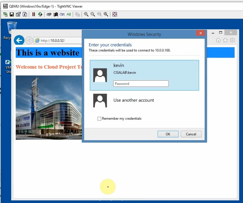
Domain users are able to access a domain controller on AWS and a web server on AWS when the domain controller on-prem was down.