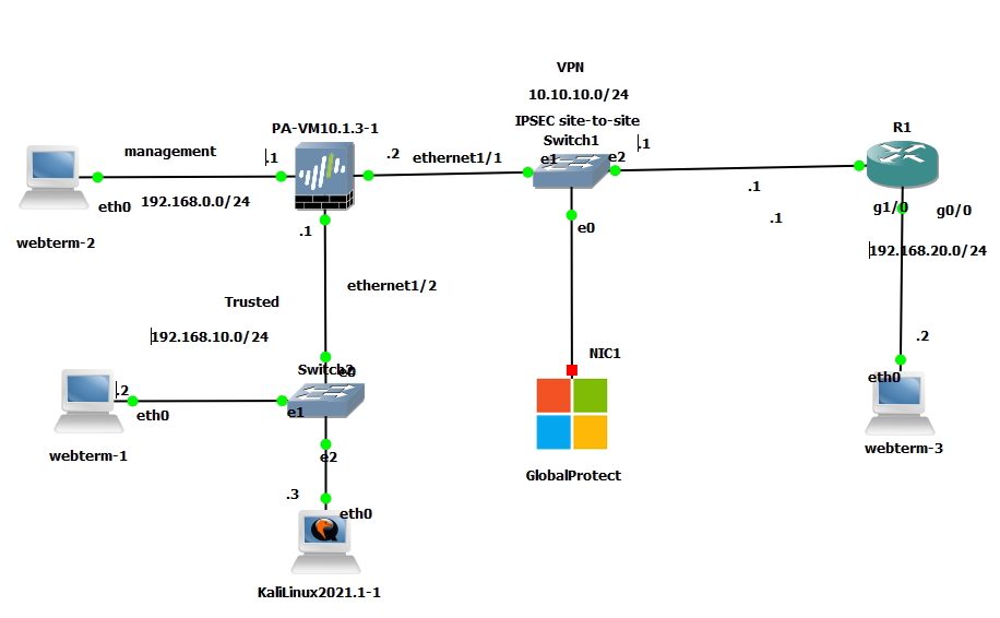
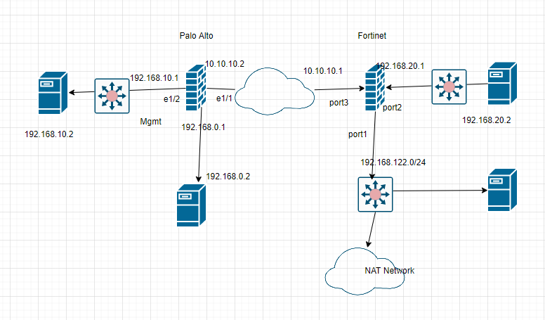
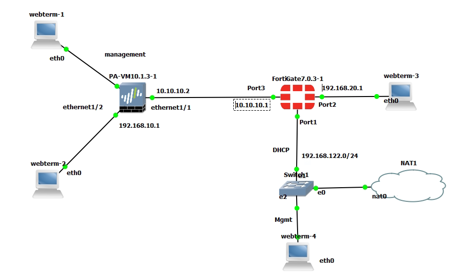
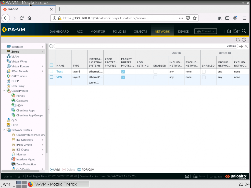
This is the lab to use to set up the IPSEC site-to-site tunnel between both devices.
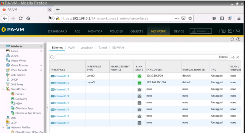
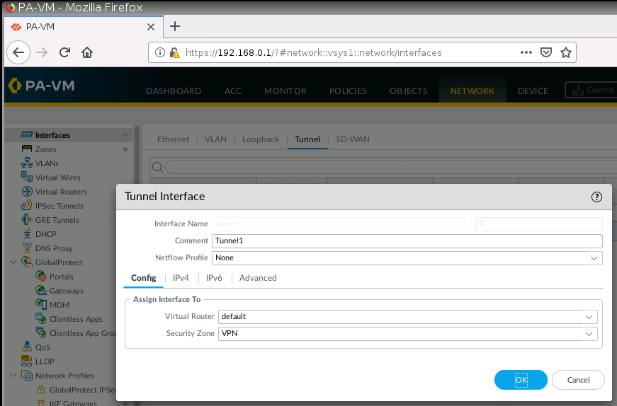
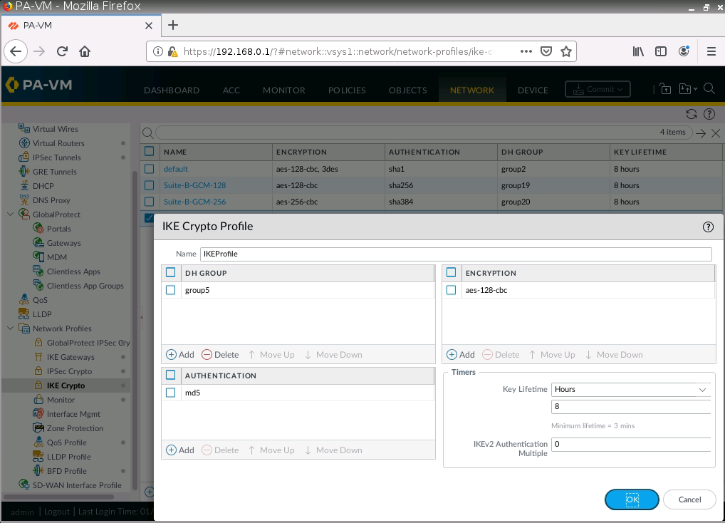
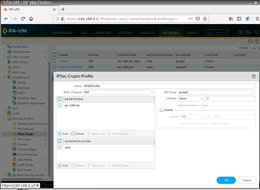
On Palo Alto.
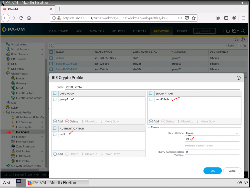
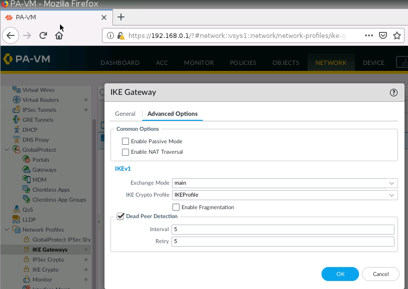
IKE Crypto.
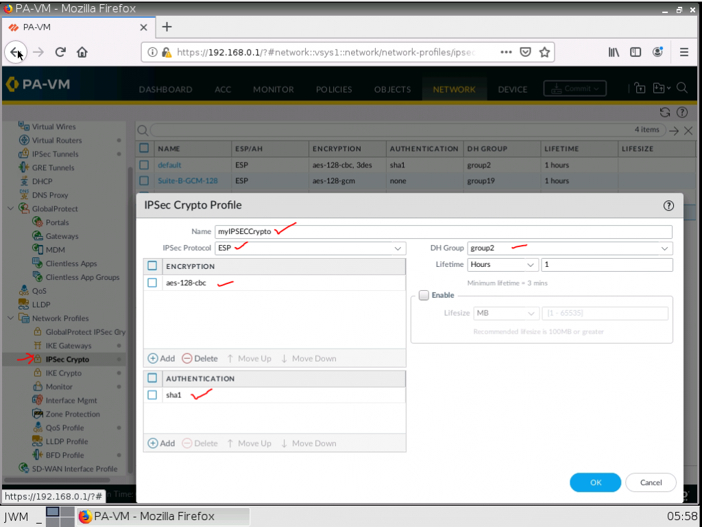
IPSEC Crypto.
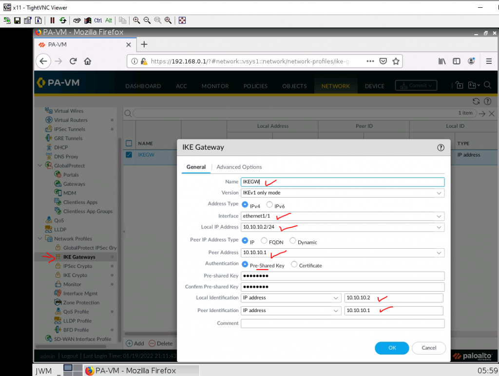
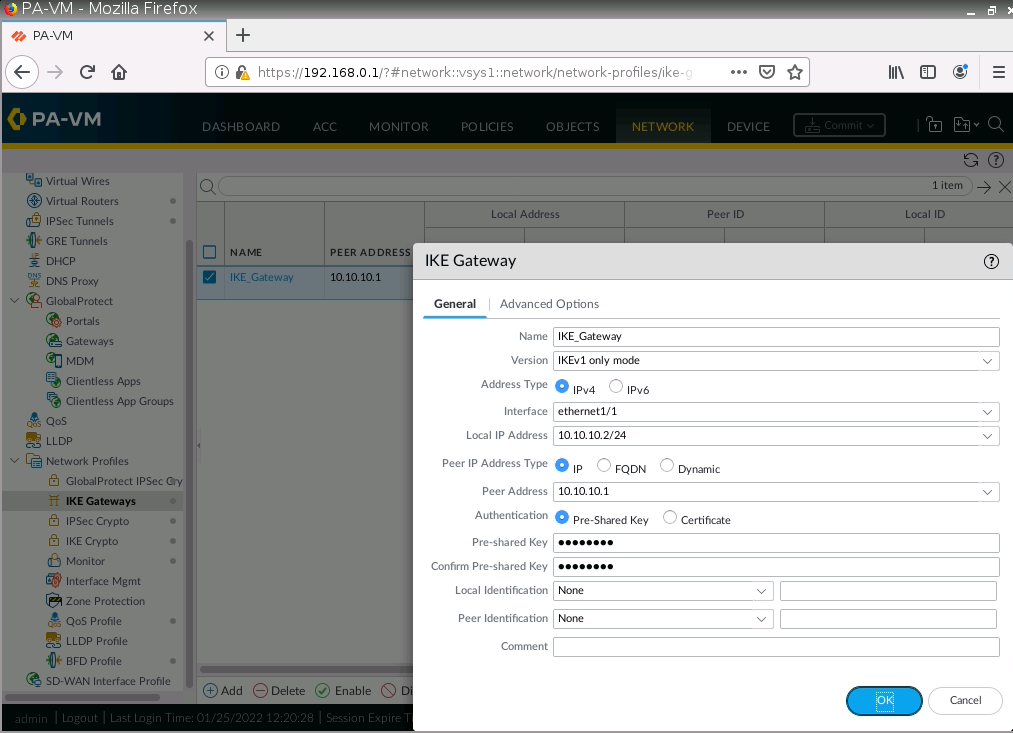
IKE Gateway.
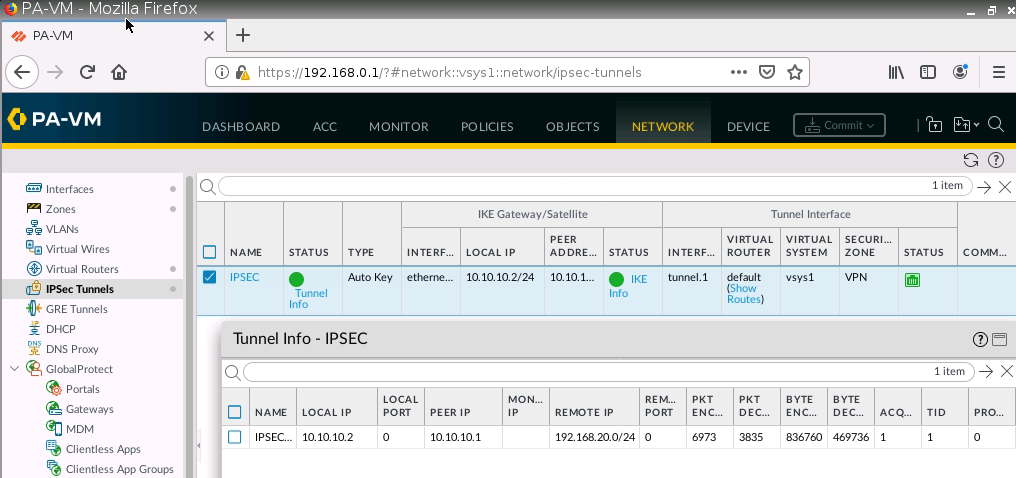
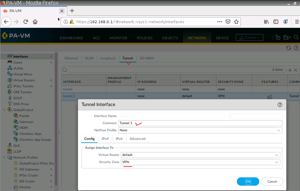
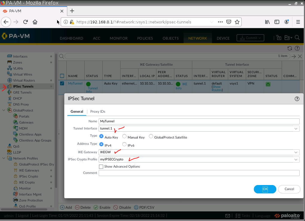
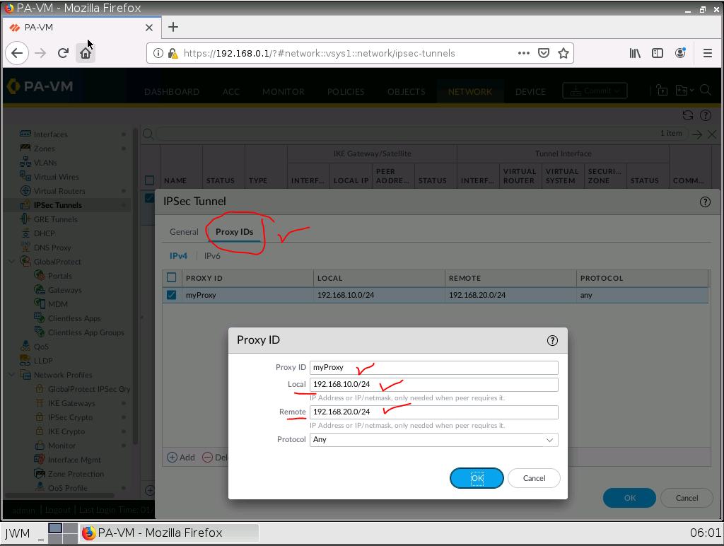
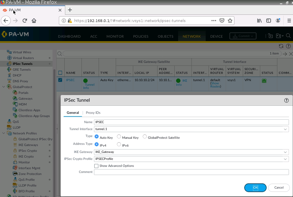
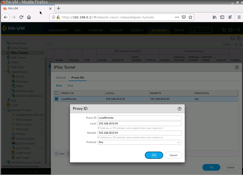
IPSec tunnel.
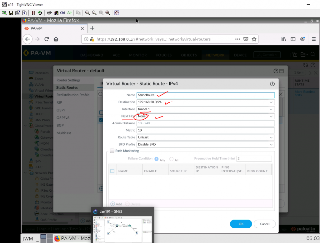
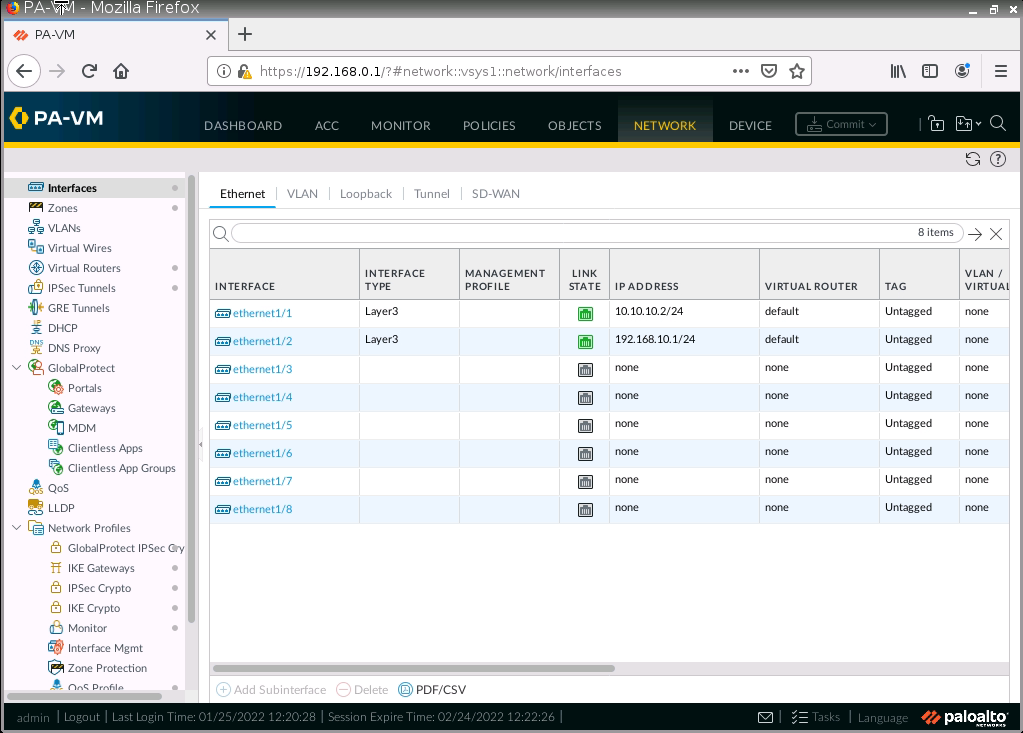
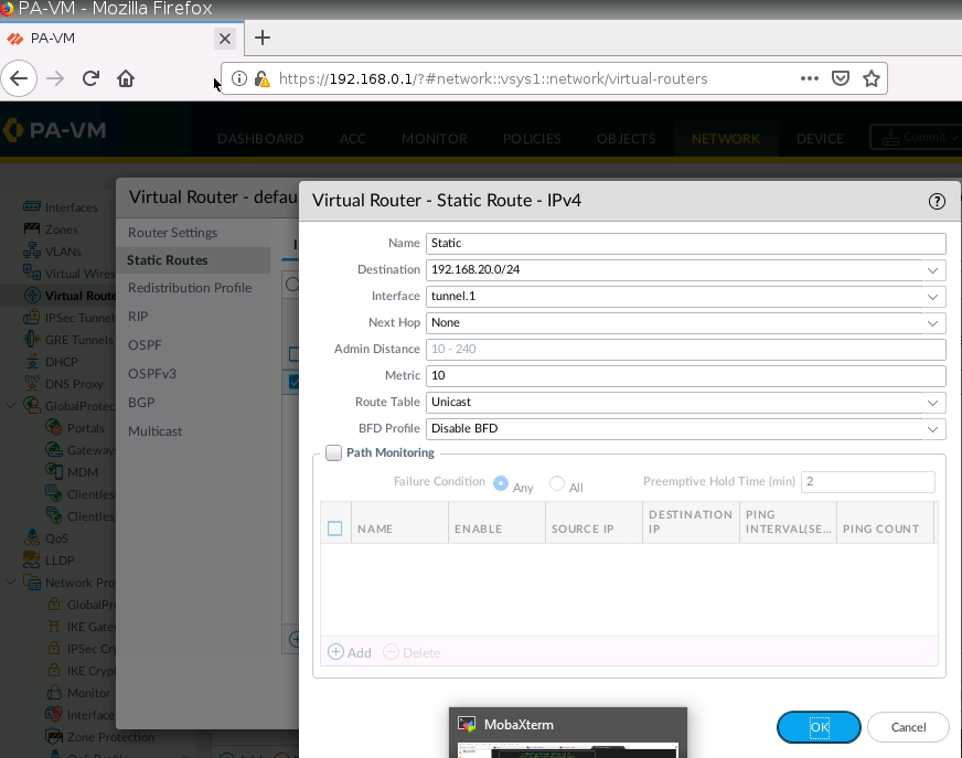
Create a virtual route from PA to Fortinet.
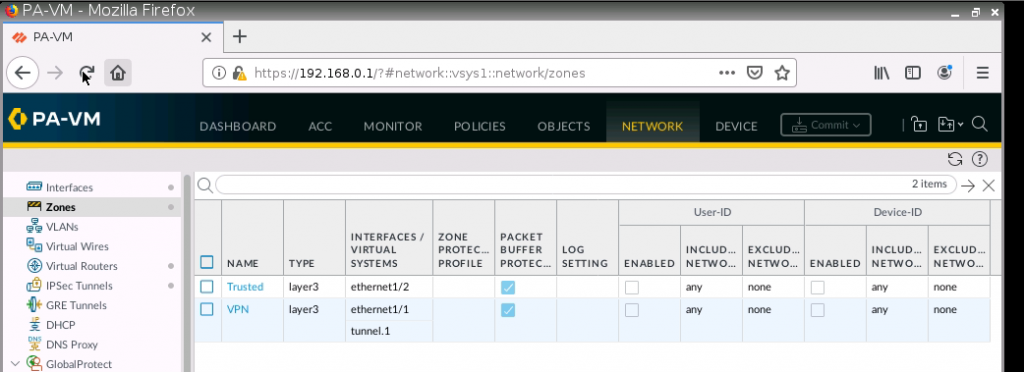
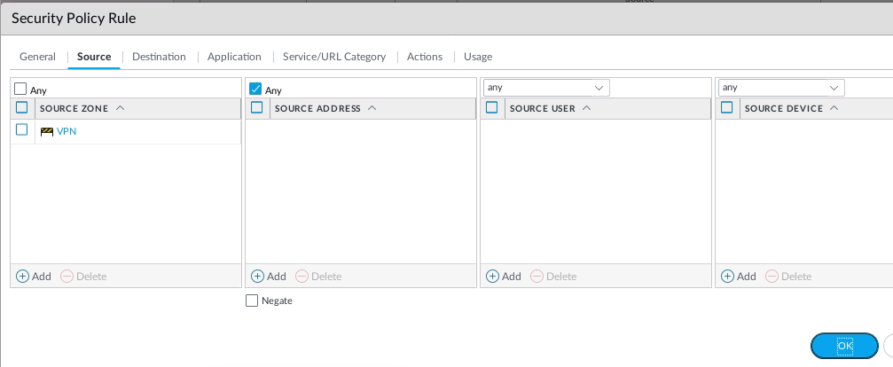
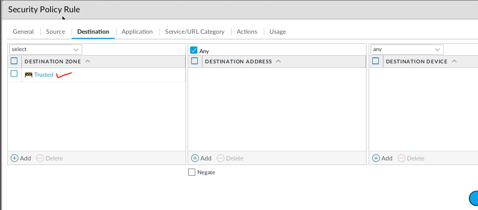
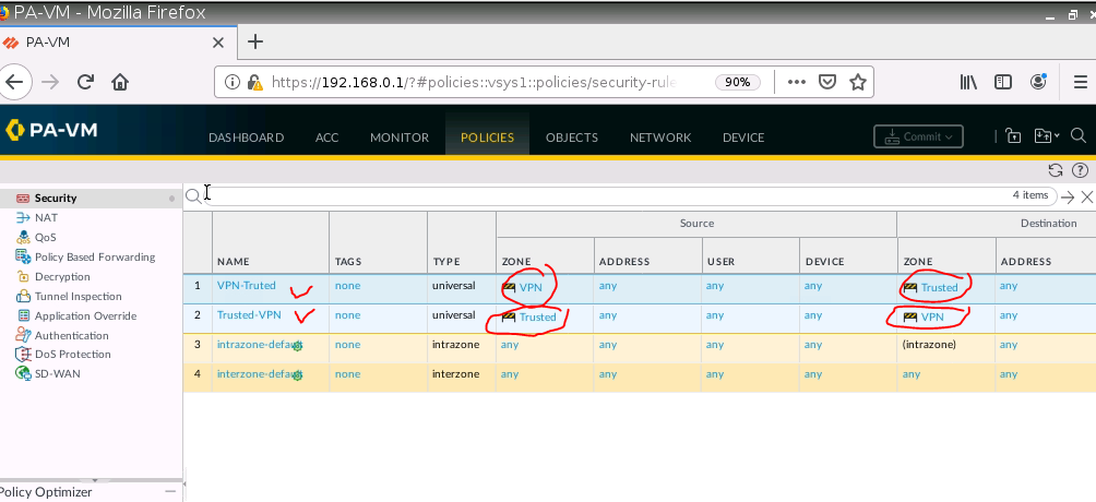
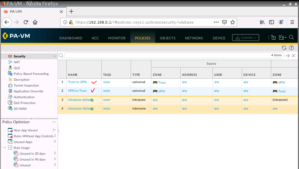
Create two Security Policies to allow traffic from the “Trusted Zone” of PA to the “Trusted Zone” of Fortinet.
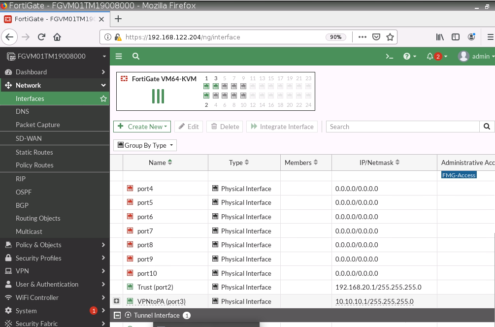
Configure Fortinet.
config system interface
edit port1
set mode dhcp
set allowaccess ping httpd http fgfm
next
end
show system interface
# show system interface to get IP Address from DHCP
Go to Webterm to configure Fortinet.
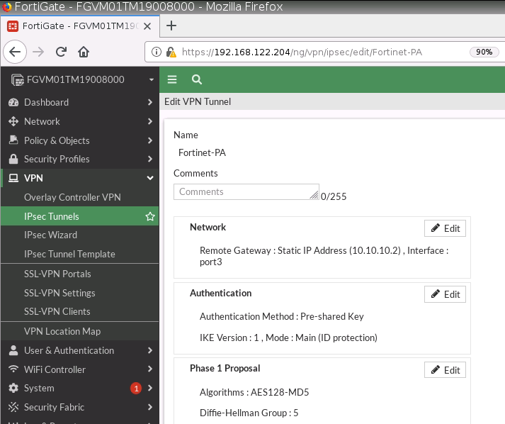
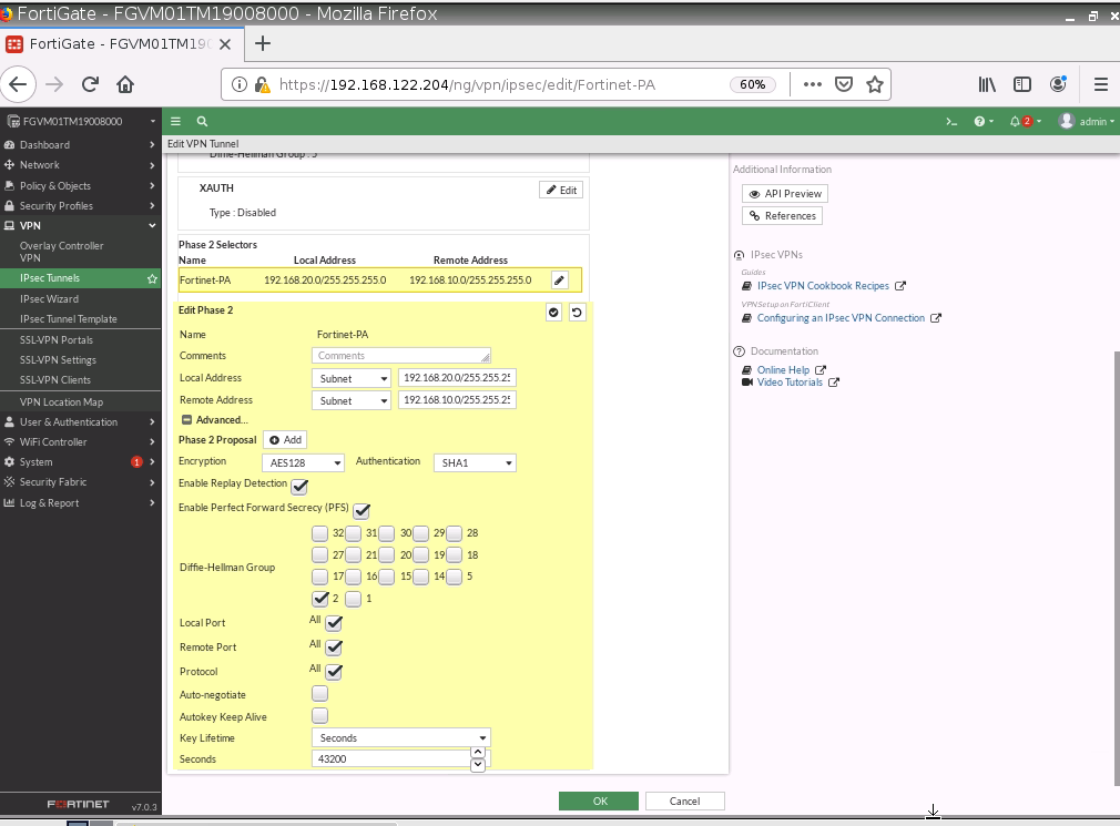
Configure a custom VPN Tunnel with the following information.
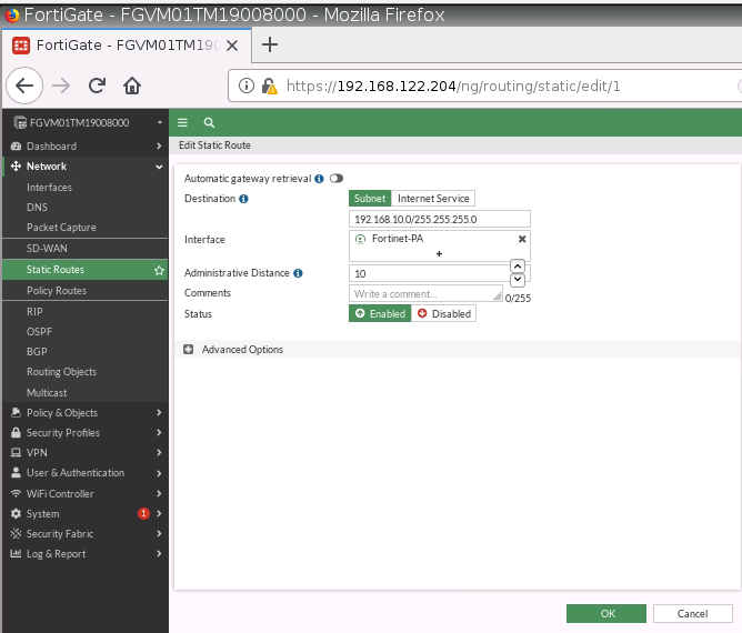
Configure a static route to allow traffic from Trusted Zone (192.168.20.0/24) on Fortinet to the Trusted Zone (192.168.10.0/24) on PA.
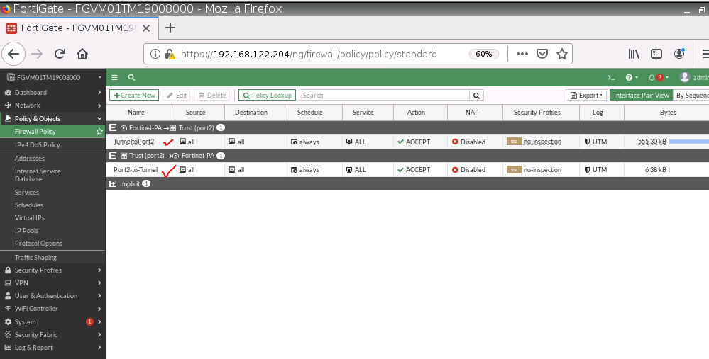
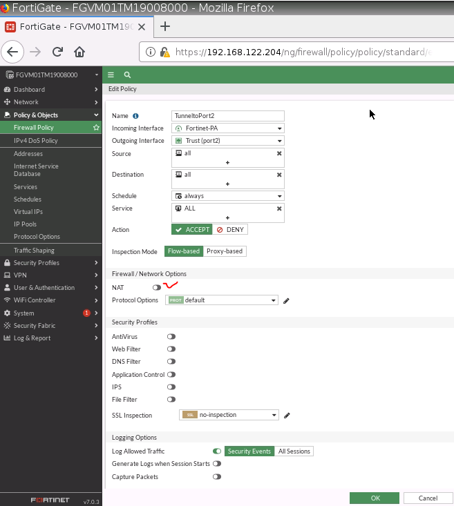
Create two Security policies to allow traffic from VPN to Trusted Zone and vice versa.
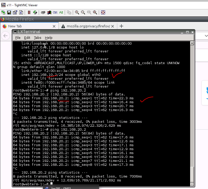
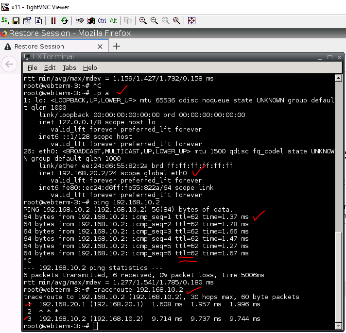
Ping and traceroute from a VM on Fortinet to another VM on Palo Alto.
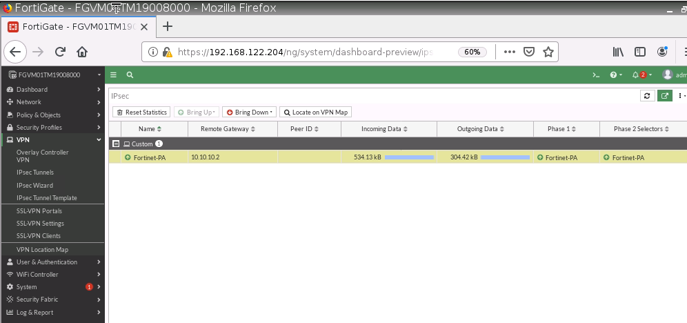
Monitor IPSEC tunnel on Fortinet.
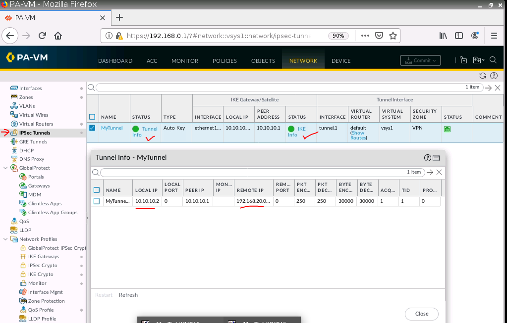
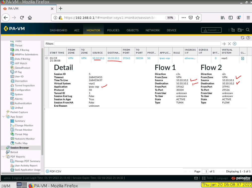
Monitor IPSEC tunnel on PA.