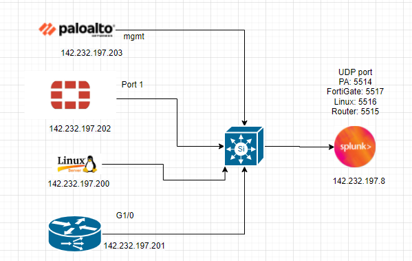
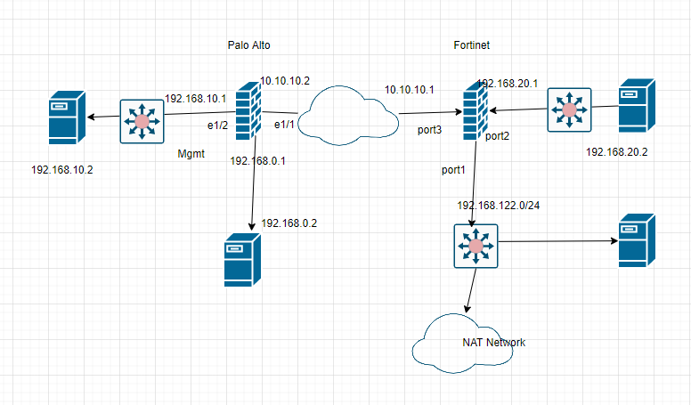
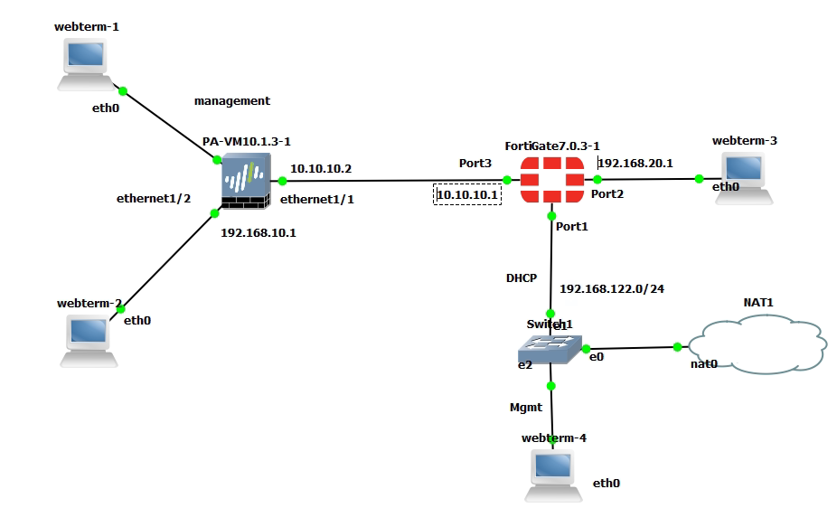
Category Archives: FortiGate

Deploying FortiGate on Amazon AWS

Diagram.

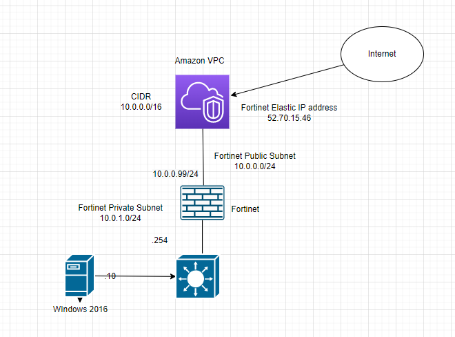
Below are a couple of steps to deploy Fortinet on AWS.
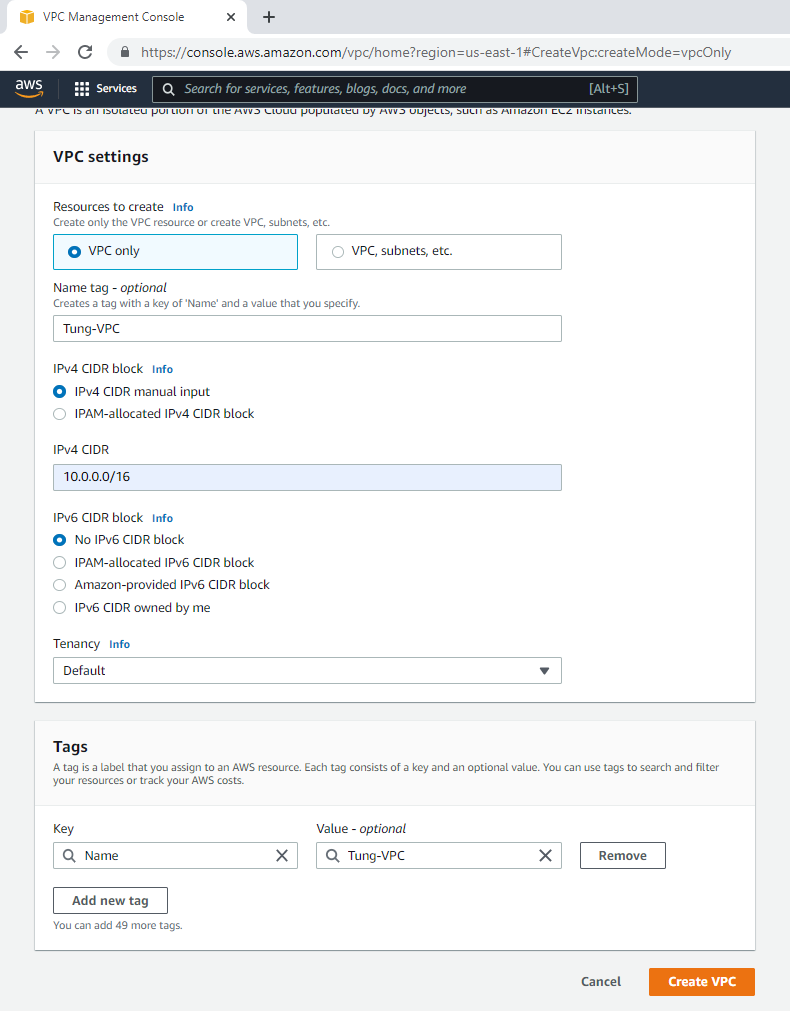
Create a new VPC.

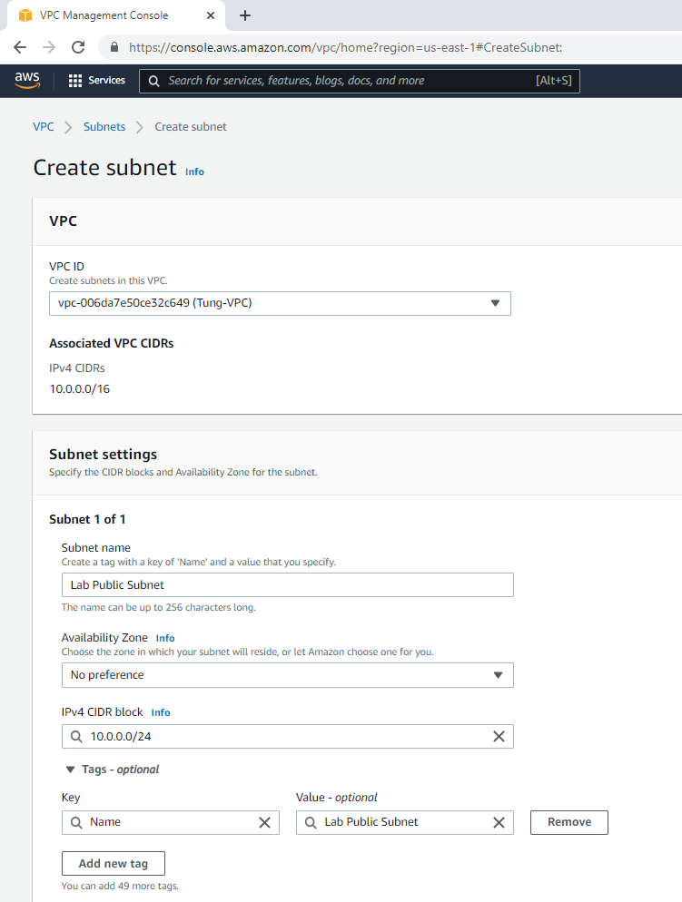
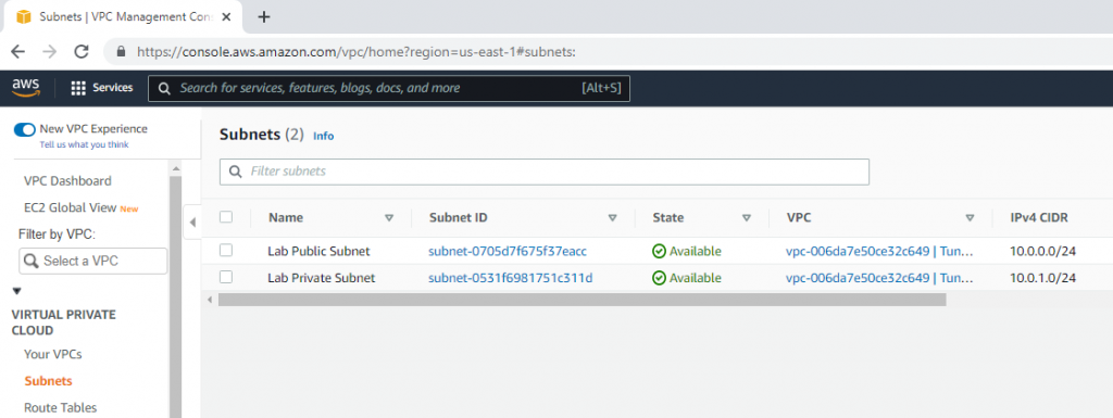
Create a public subnet.

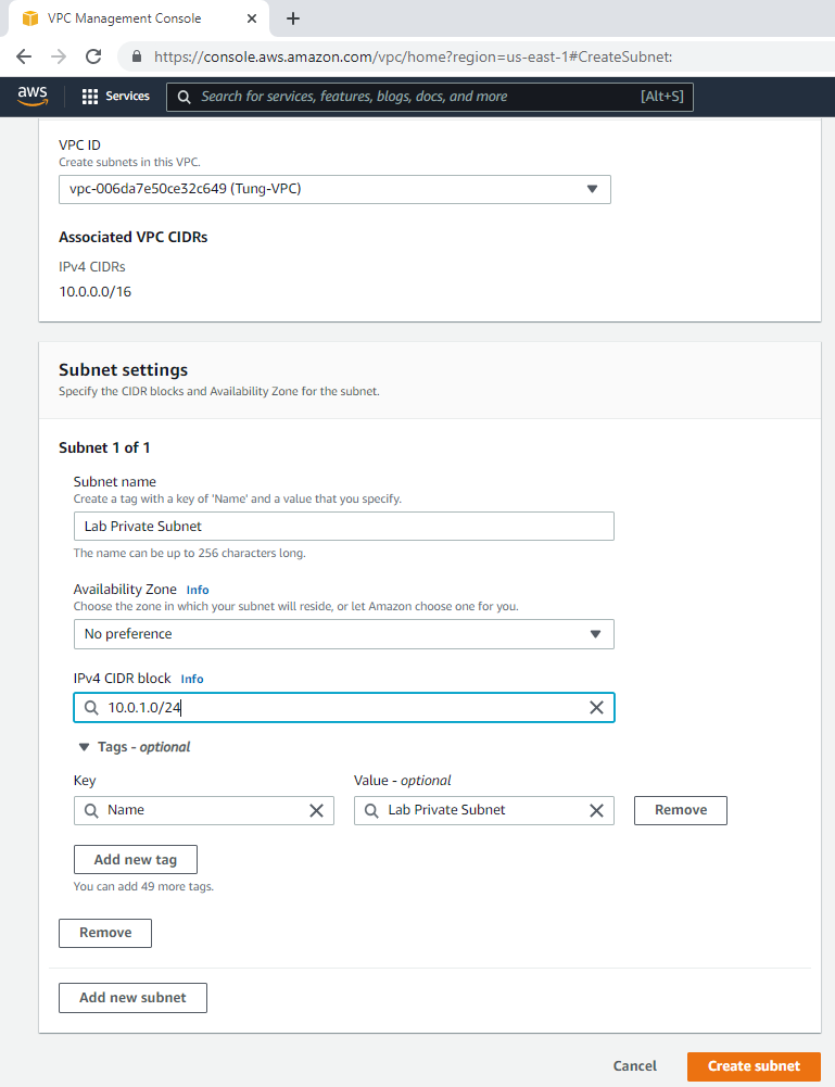
Create a private subnet.

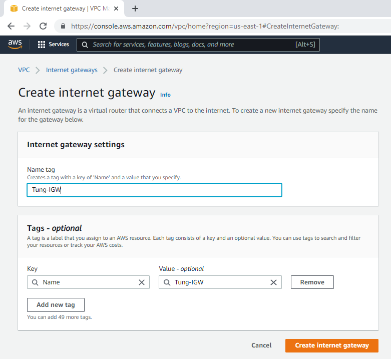
Create an Internet gateway.

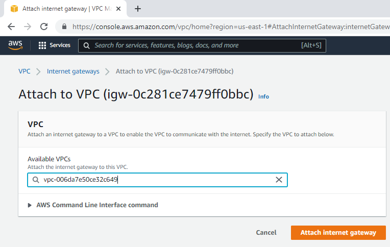
Attach the gateway to your VPC.

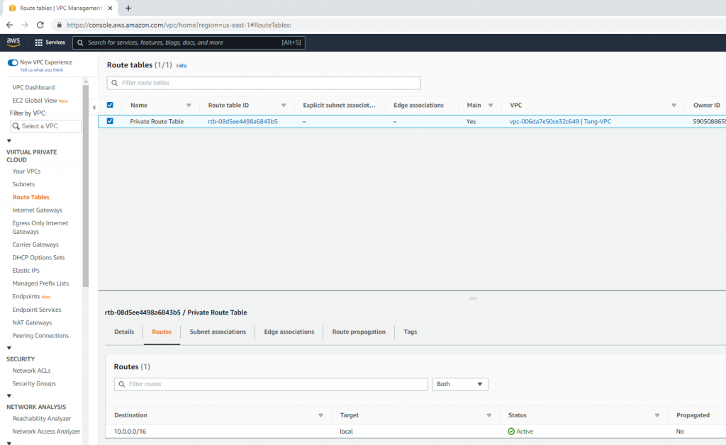
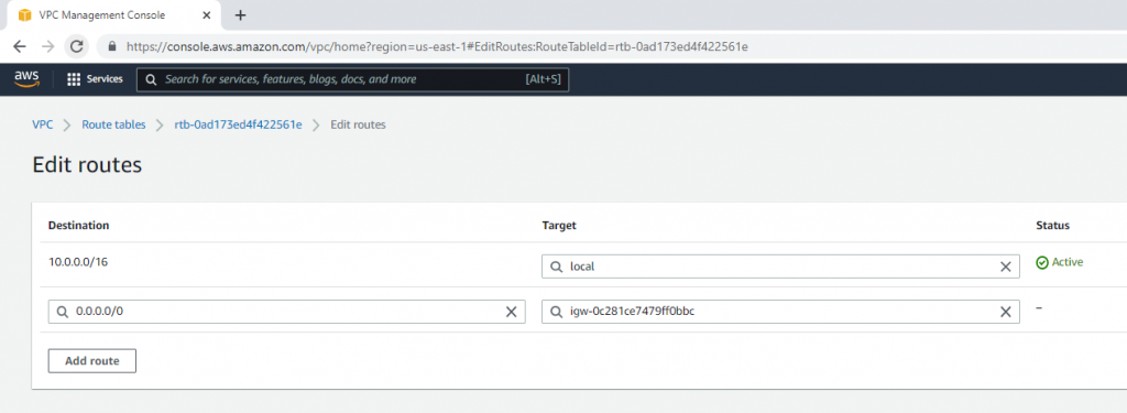
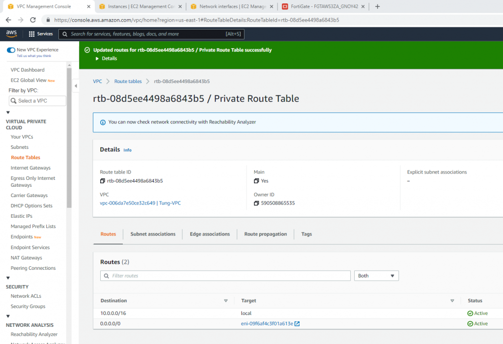
Edit Route table, change default Route table to Private Route Table.

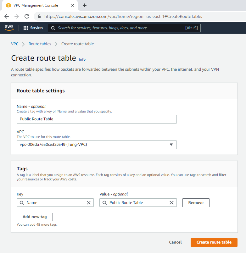
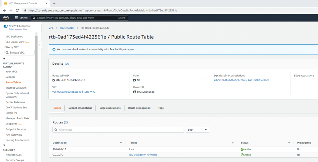
Create a Public Route Table.

Edit the route and route all traffic to Internet Gateway.

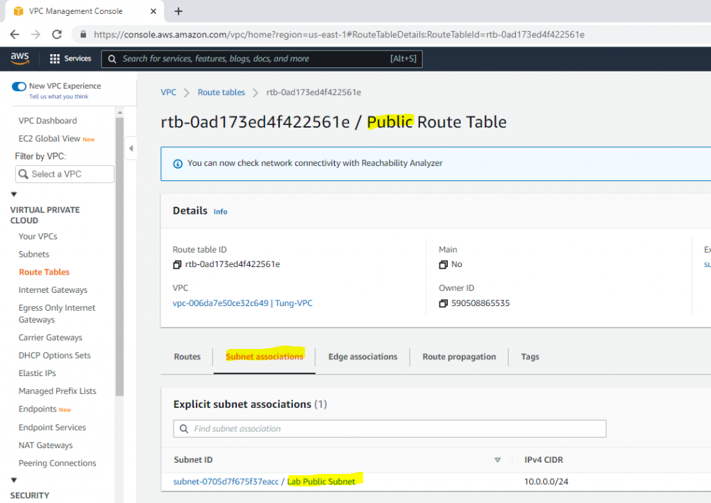
Link Lab Public Subnet to Public Route Table.

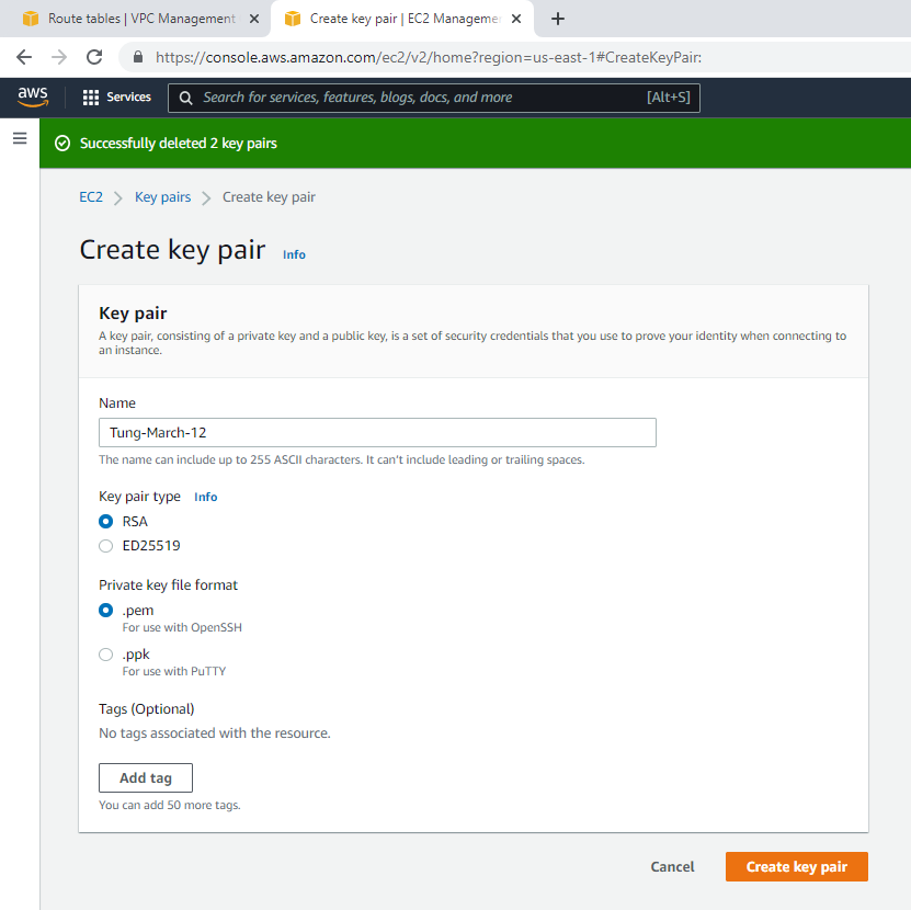
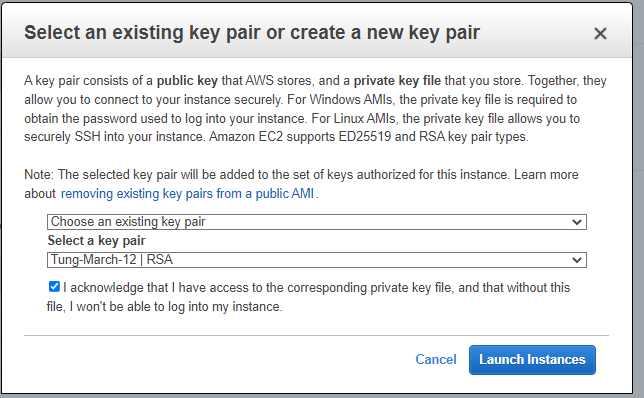
Create a new key pair.

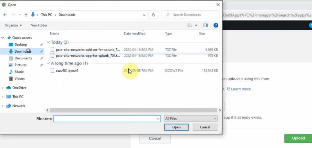
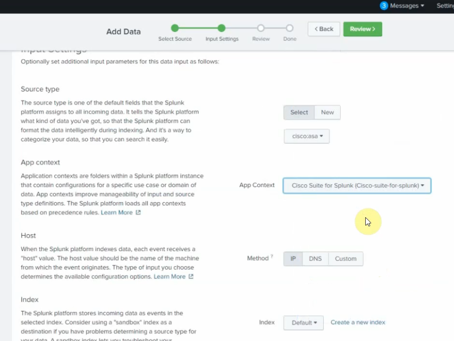
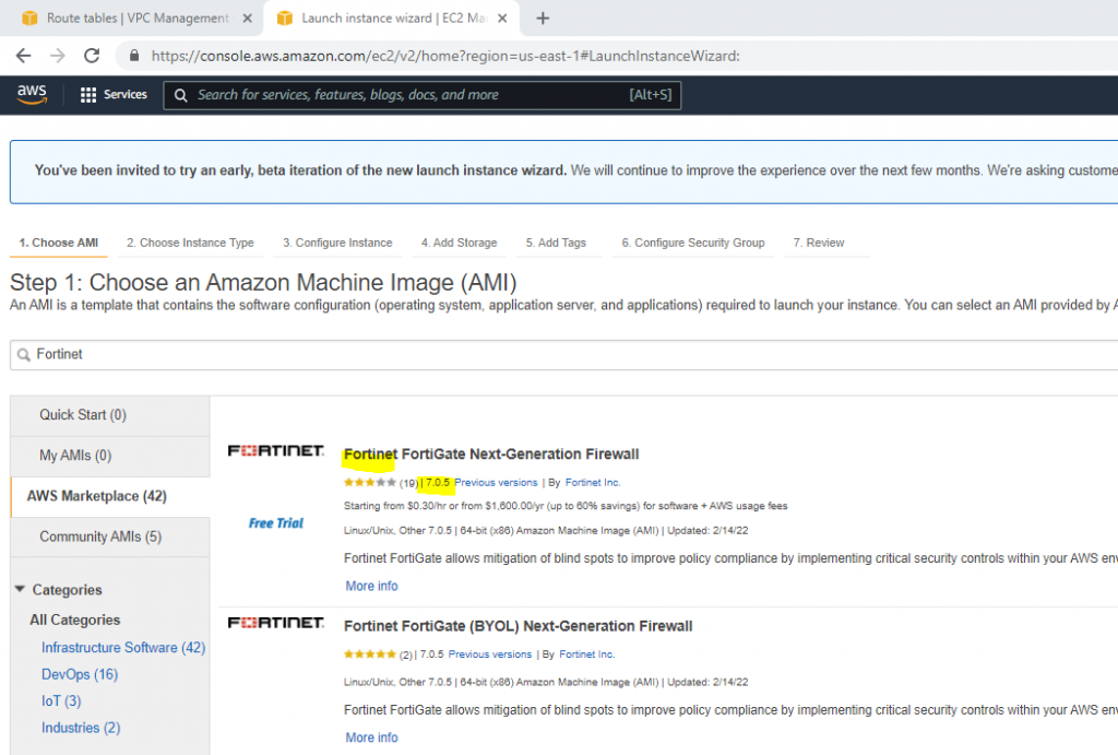
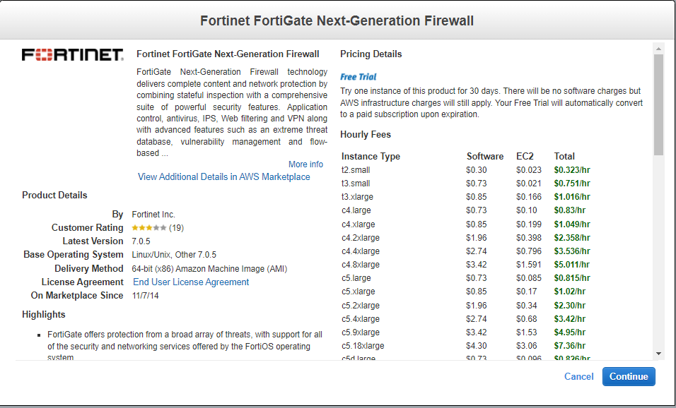
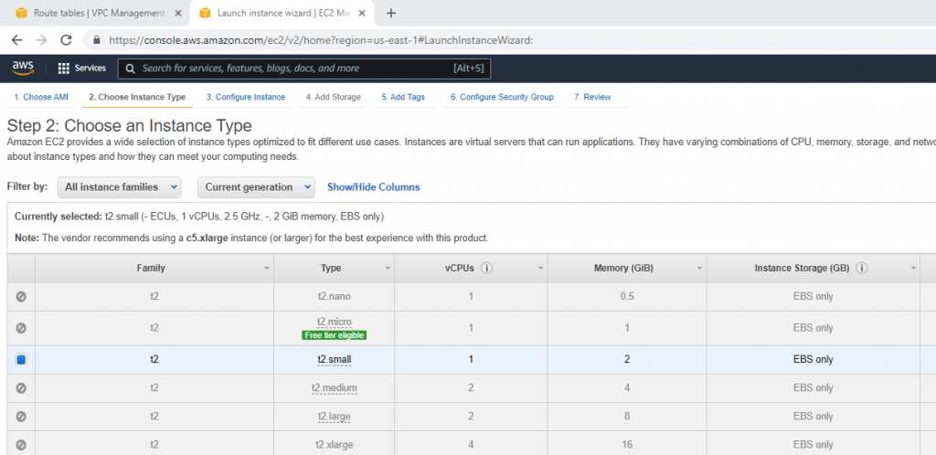
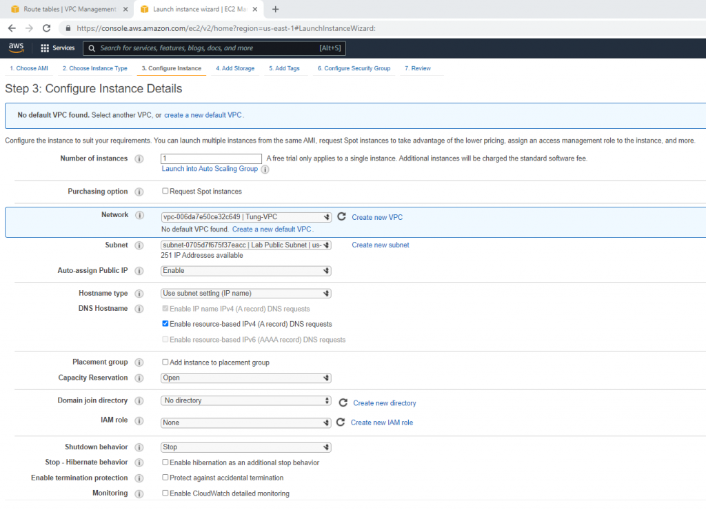
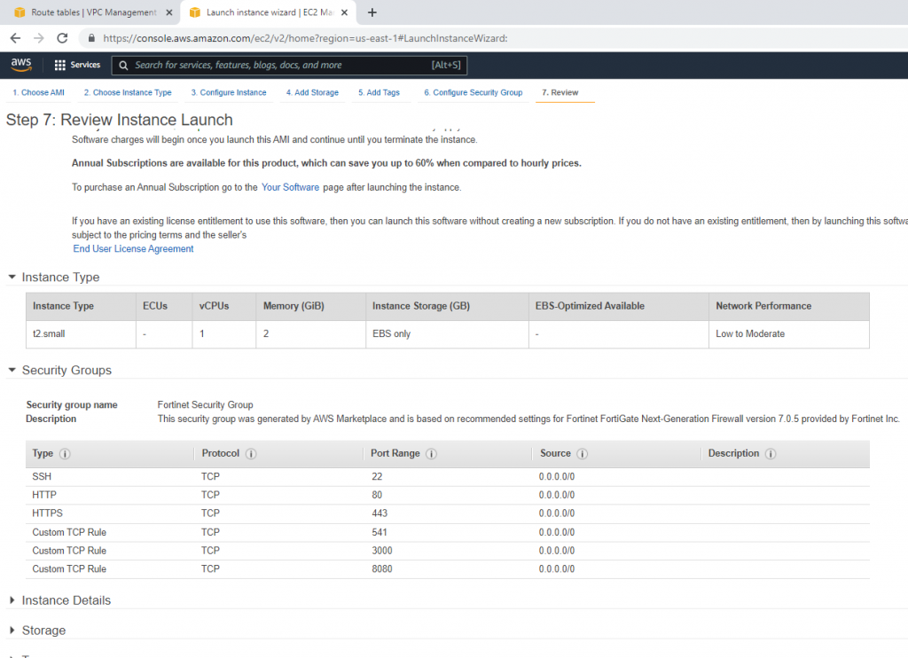
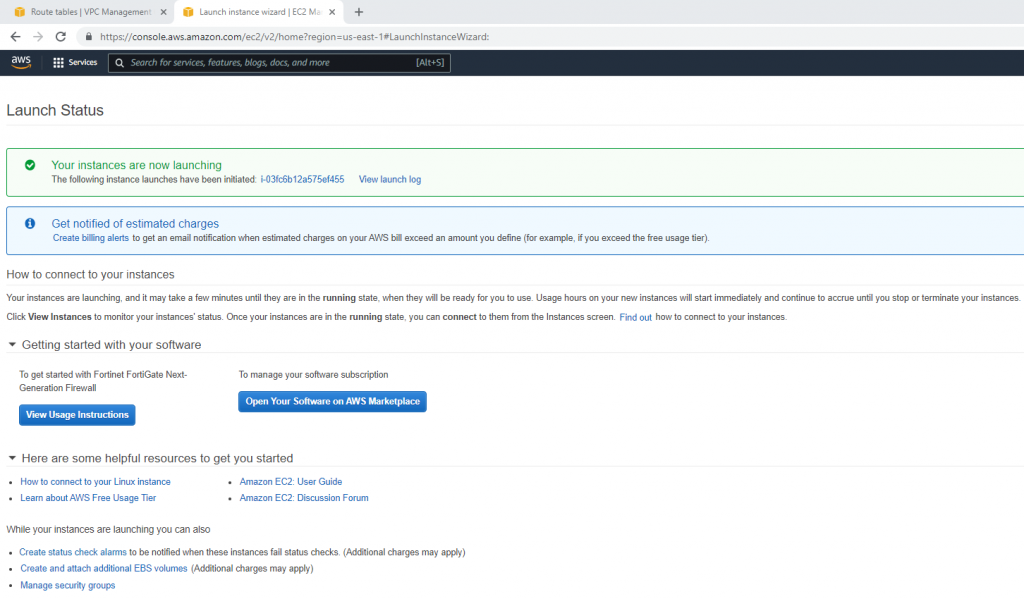
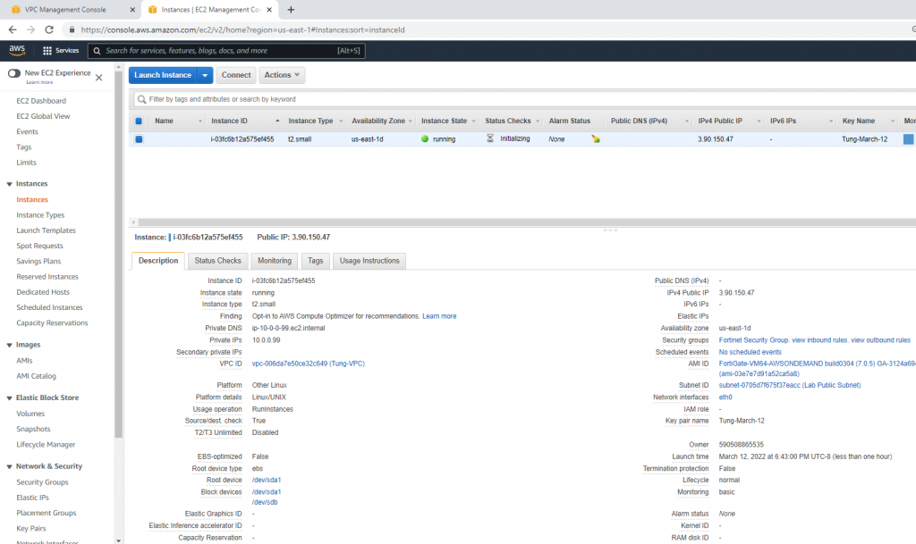
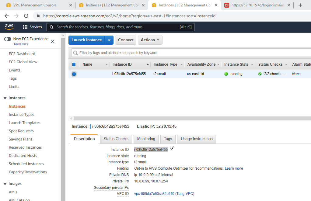
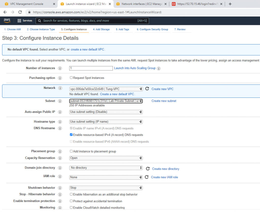
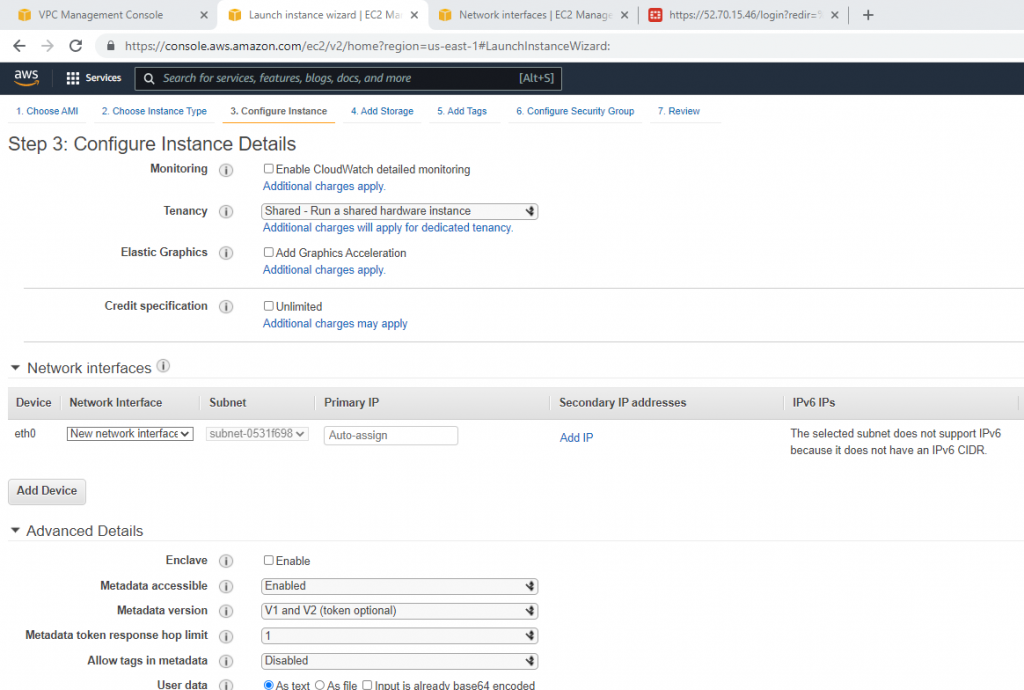
Go to EC2, and deploy Fortinet on AWS.

Select your VPC, the subnet belongs to Lab Public Subnet. Also Auto-assign Public IP is Enable.
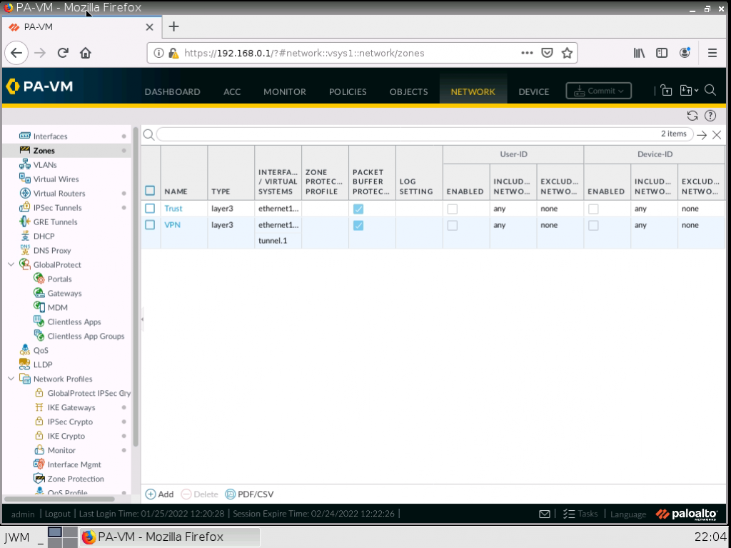
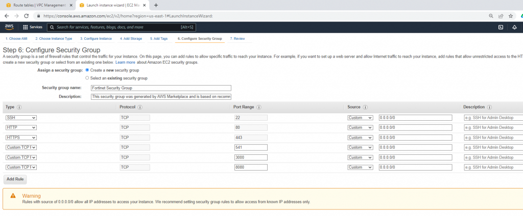
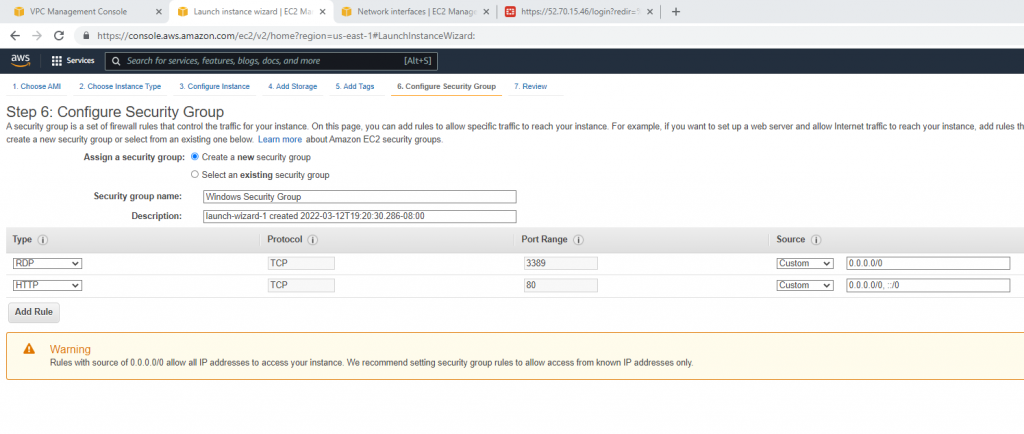
Security Group.

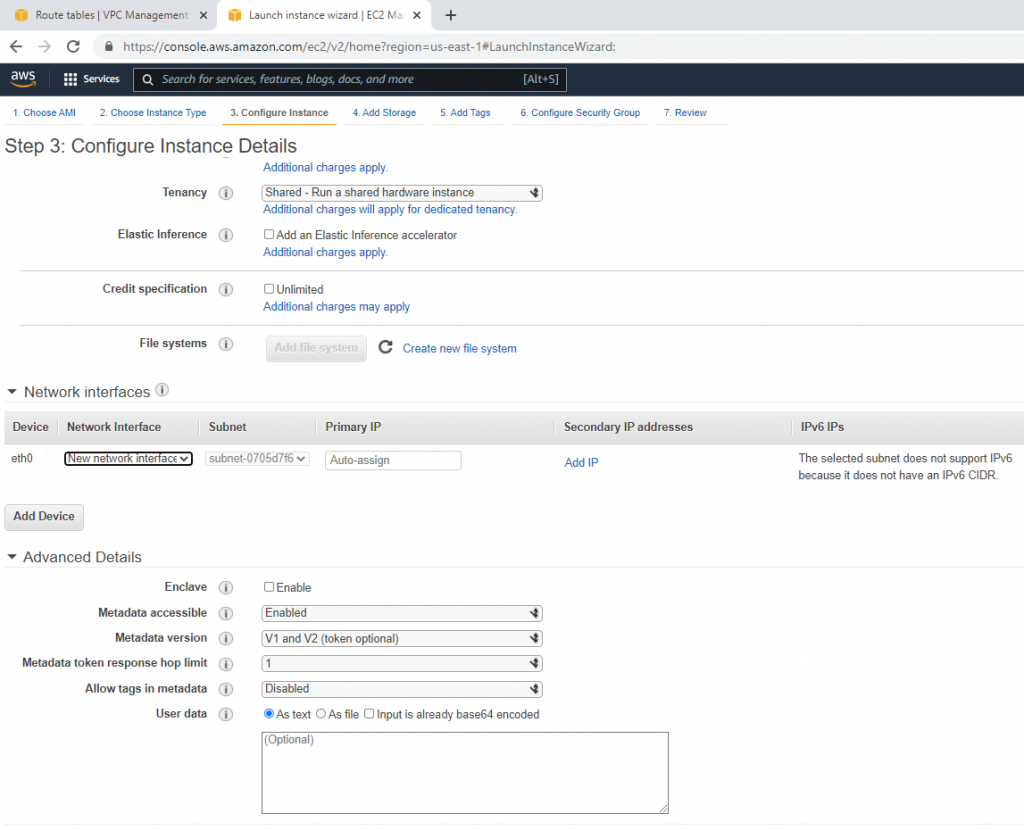
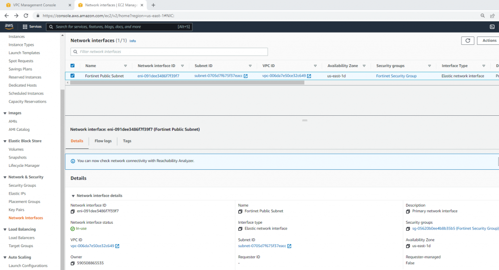
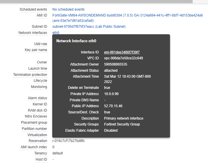
Go to Network interfaces. Change the interface to Fortinet Public Subnet.

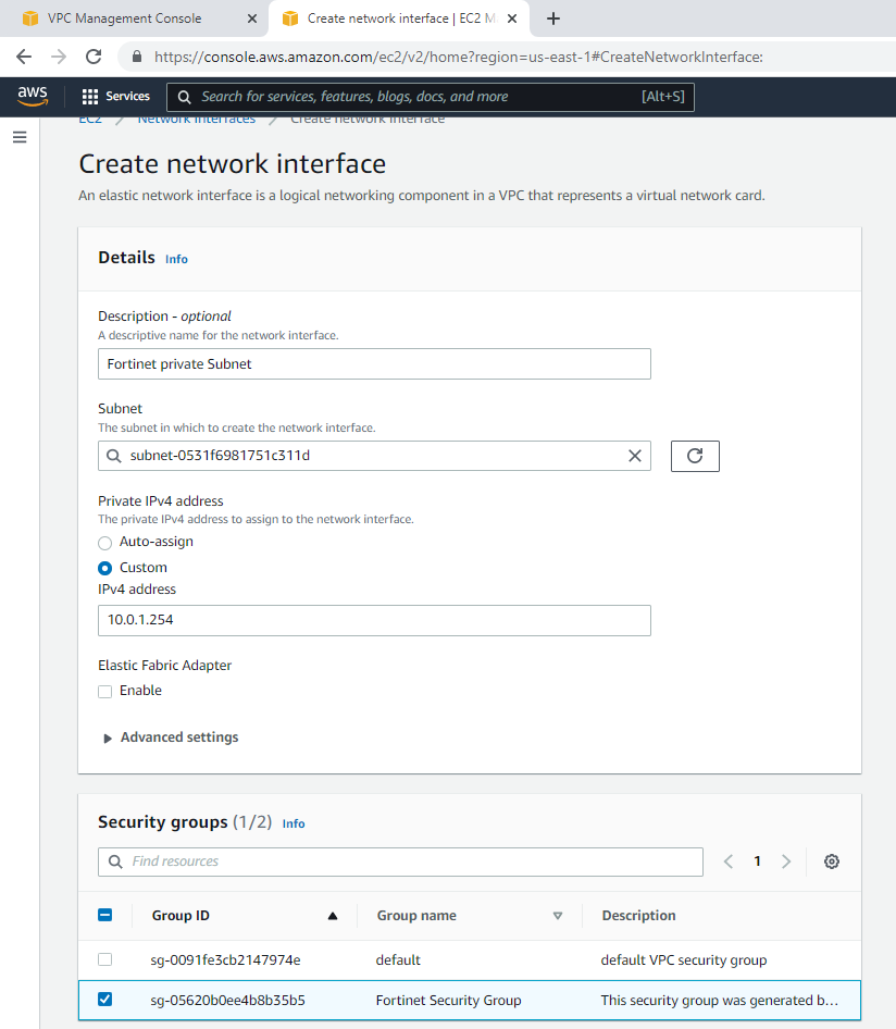
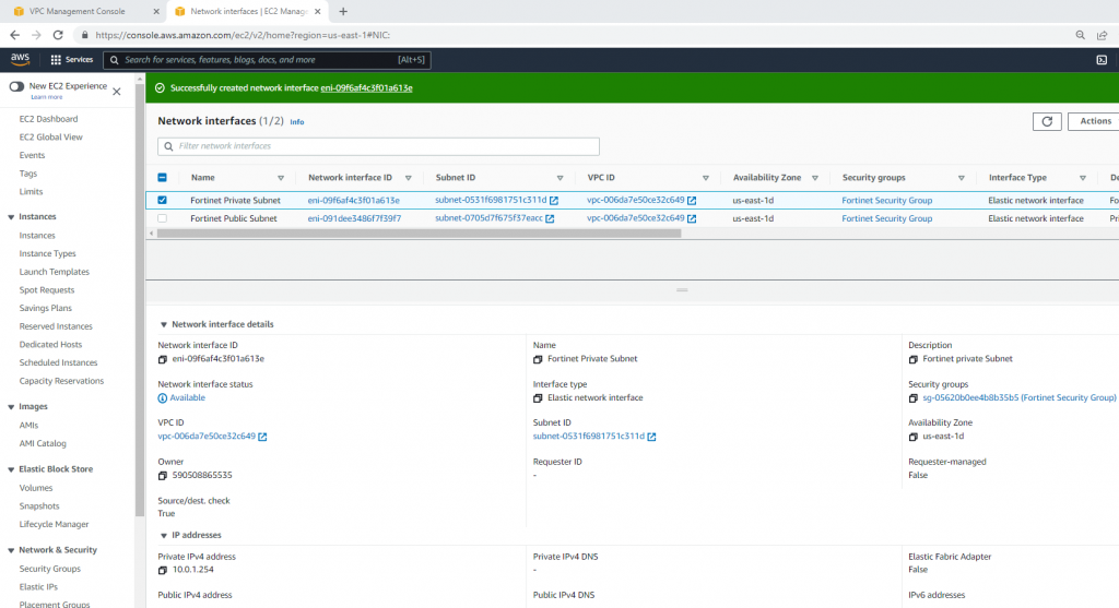
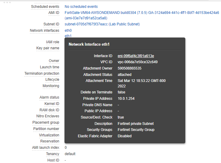
Create a new Fortinet Private subnet.

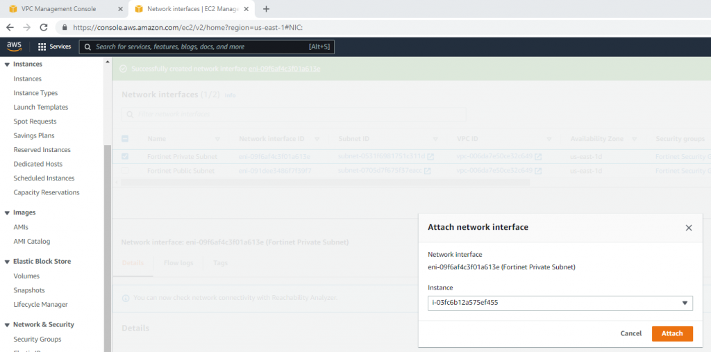
Attach this network interface to Fortinet EC2.

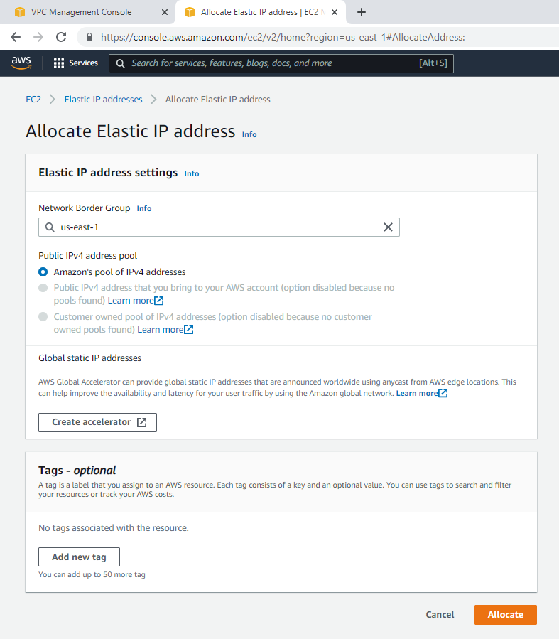
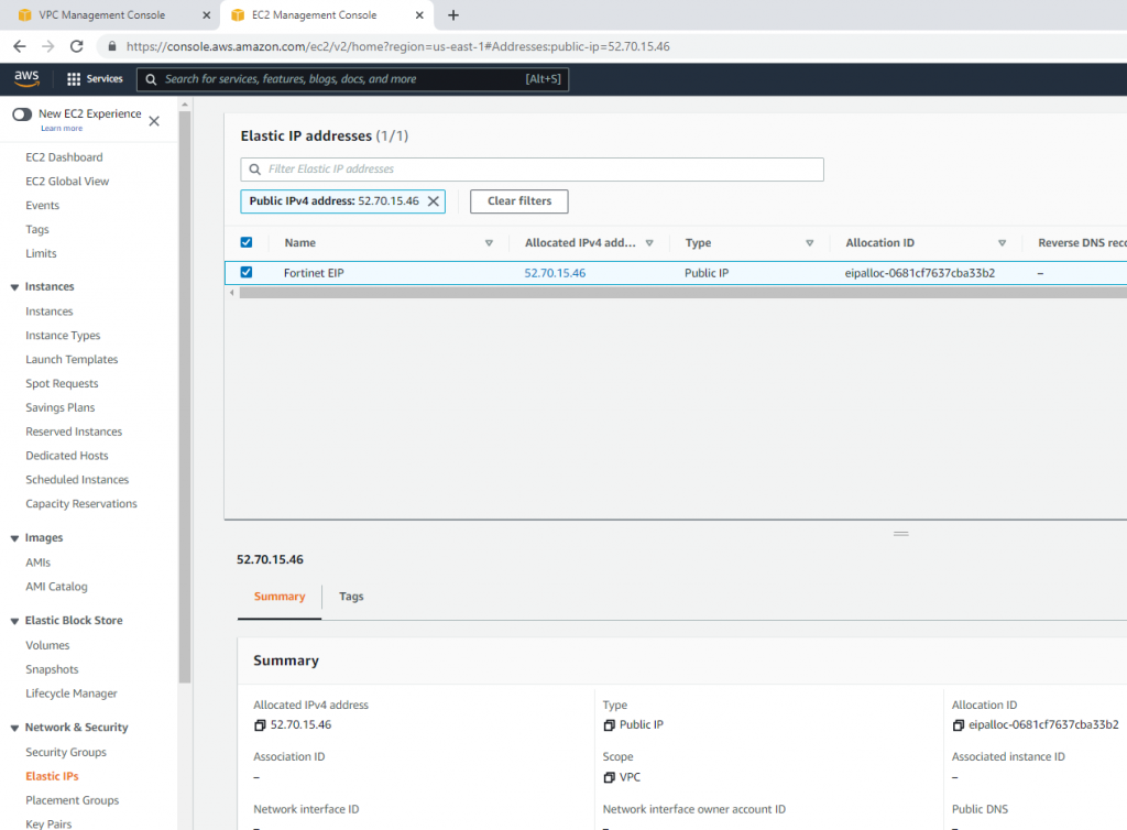
Create a new Elastic IP address.

Change to Fortinet EIP.

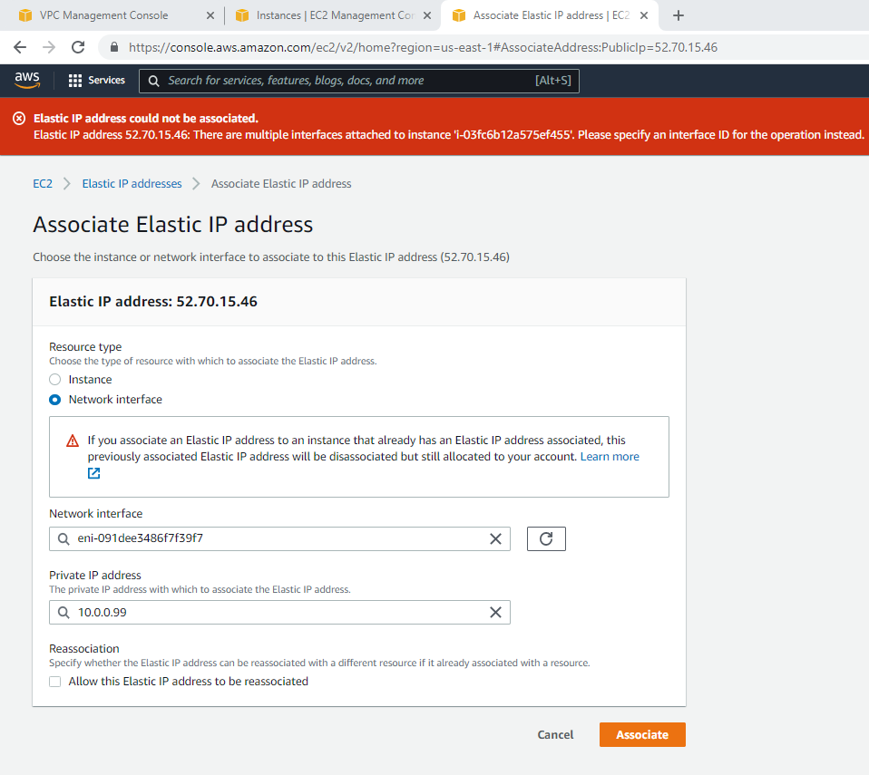
Associate this Elastic IP address to Fortinet EC2.

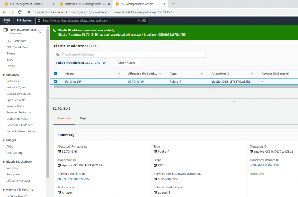
Now, Fortinet has two interfaces. One is Private, and another one is Public.

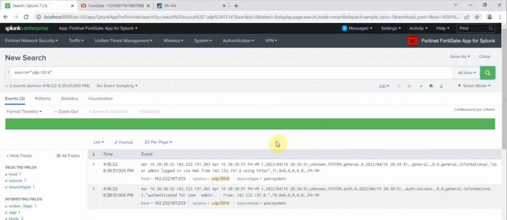
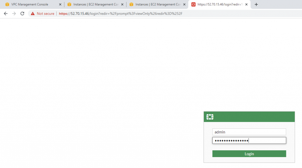
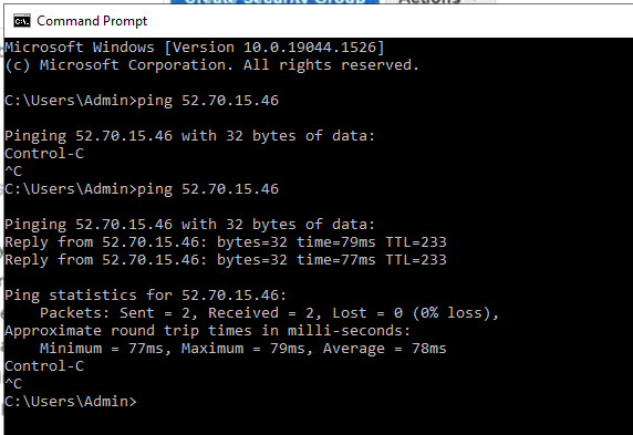
Access Fortinet via the Internet.
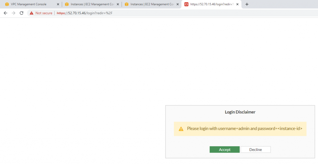
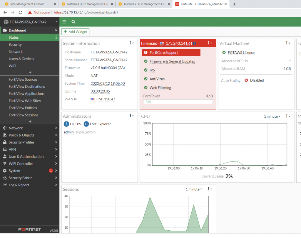
Login to Fortinet.

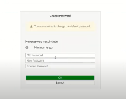
Change password to login to Fortinet.
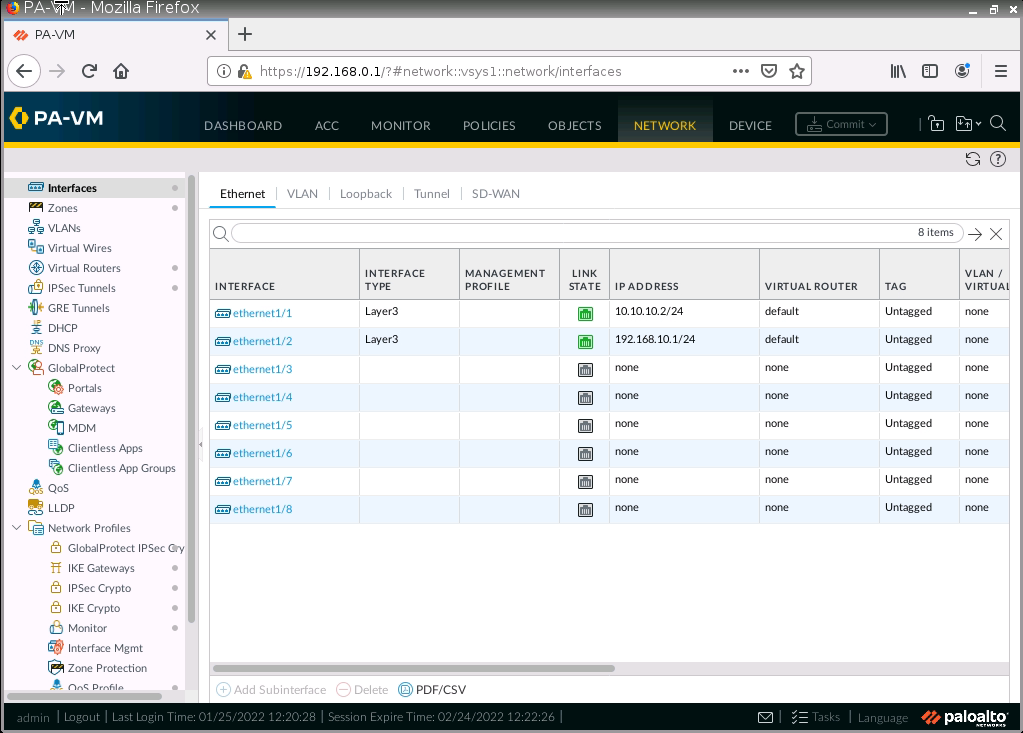
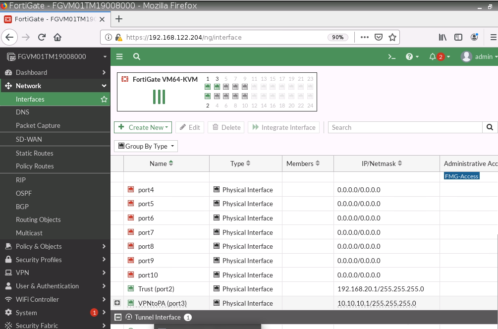
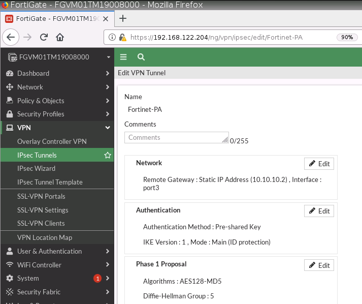
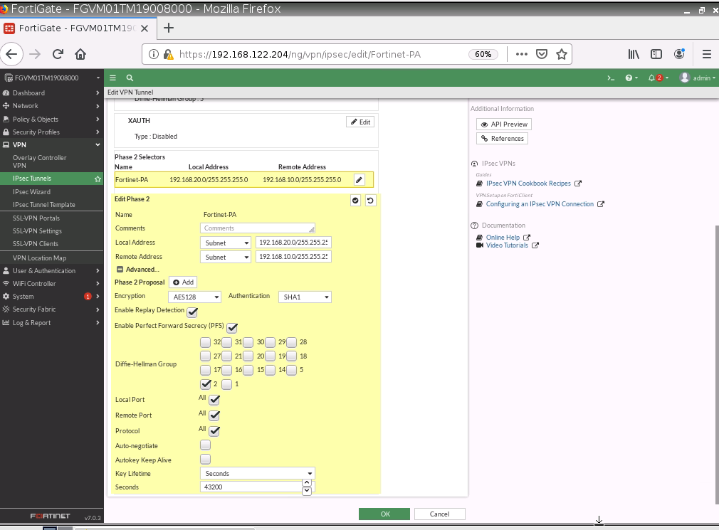
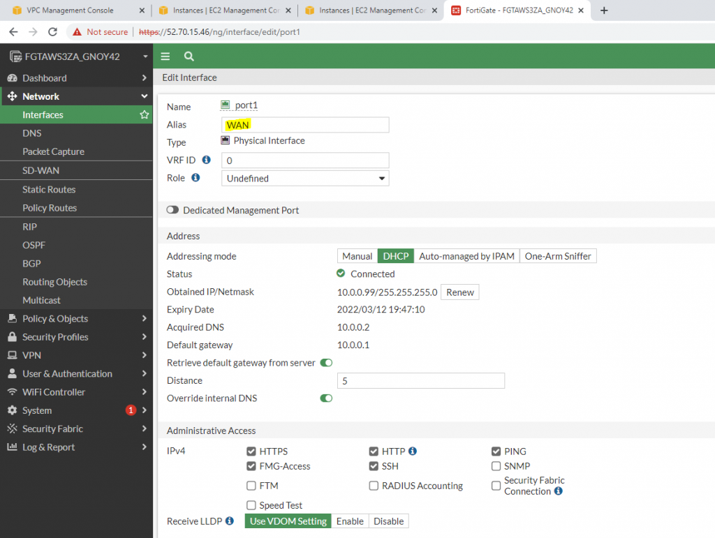
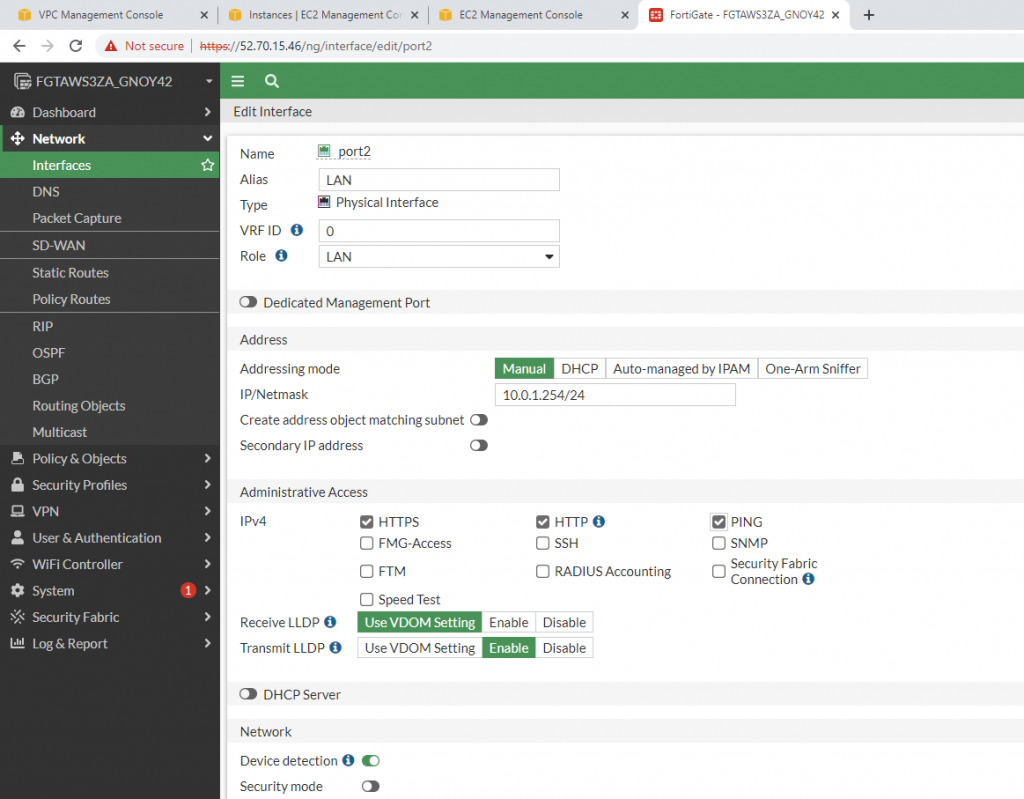
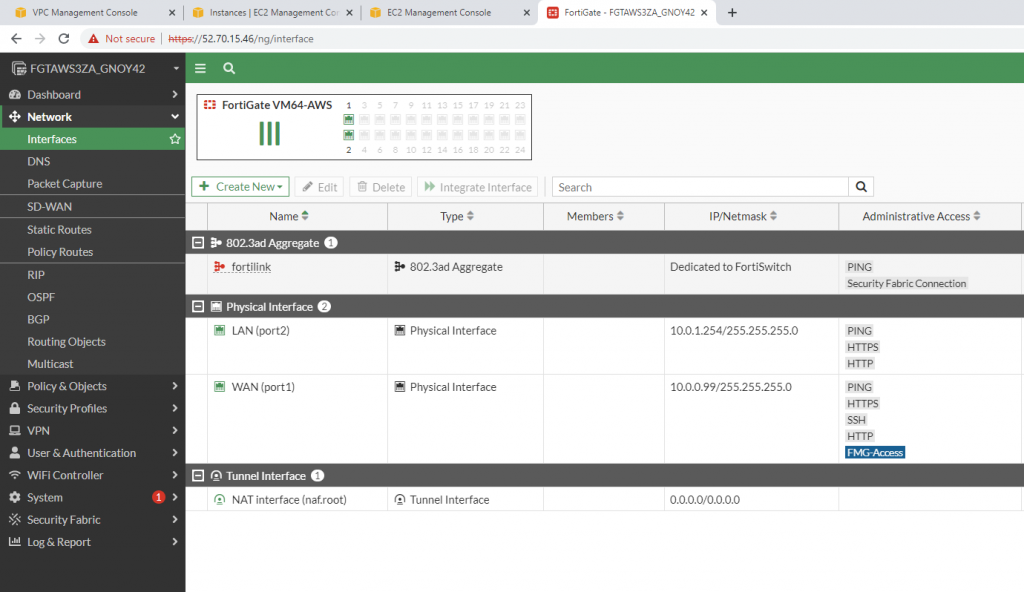
Edit interfaces.

WAN interface.

LAN interface.

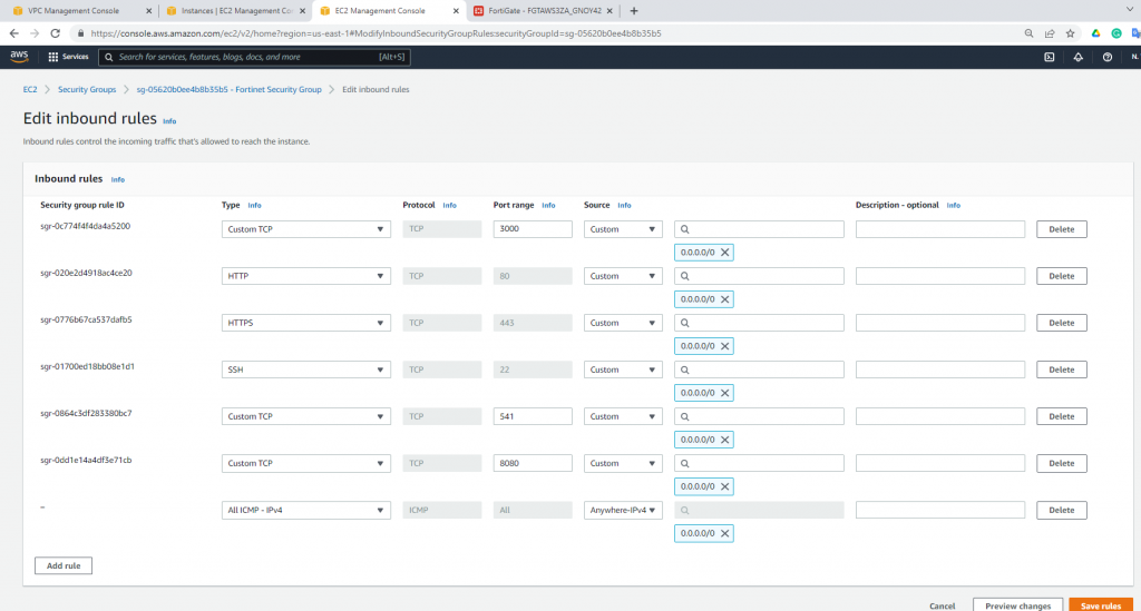
Edit Security Group to allow to ping Fortinet.

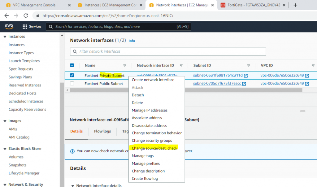
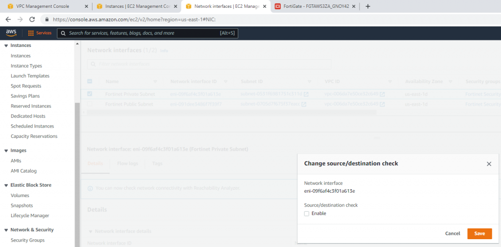
Disable Source and Destination Check on “Fortinet Private subnet”.

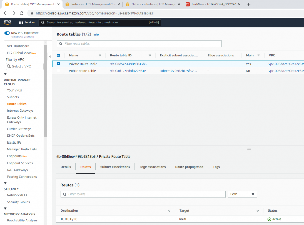
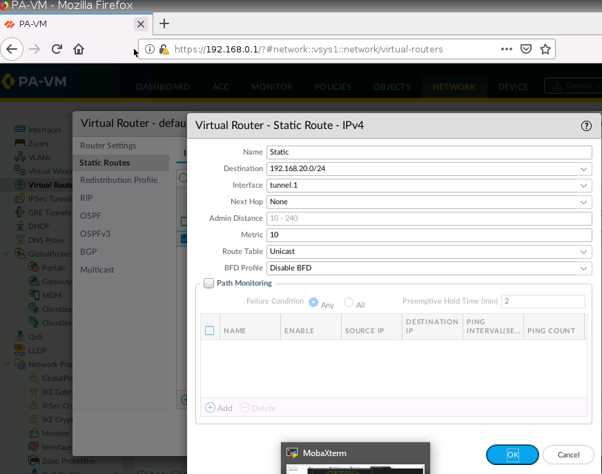
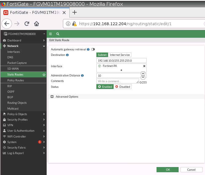
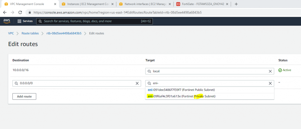
Now, change the route to route private subnet traffic via Fortinet Private subnet interface.

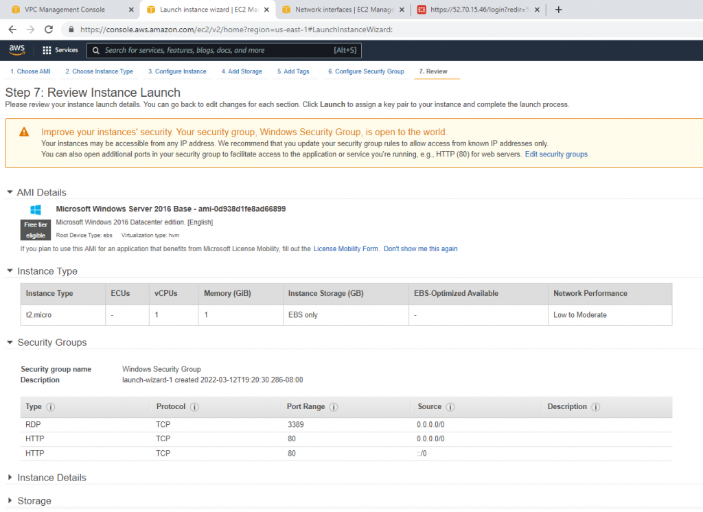
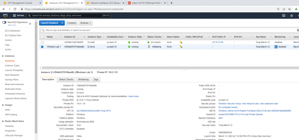
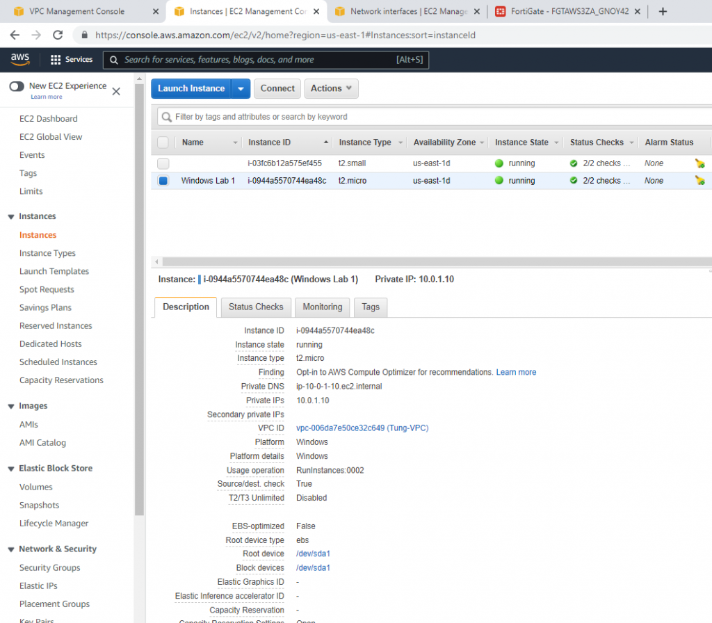
Create a new Windows 2016 VM EC2. The machine is belonged to “Lab private Subnet”.

Create a new Windows Security Group to allow HTTP and RDP traffic.

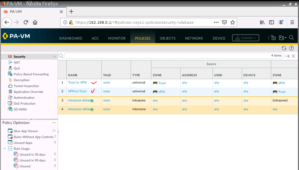
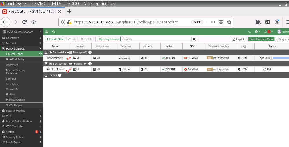
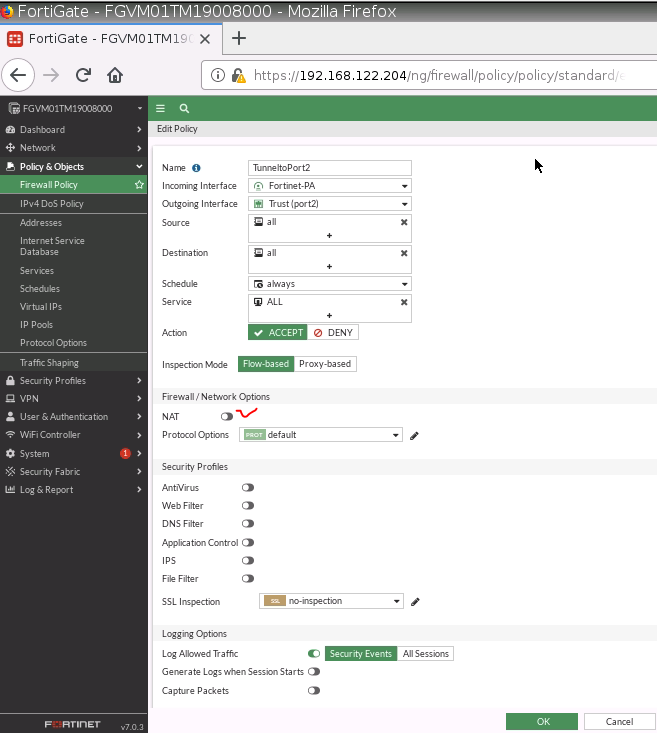
Back to Fortinet to configure FIrewall Policy to allow traffic from Fortinet Private subnet to access the Internet.

Configure port forwarding to allow traffic.

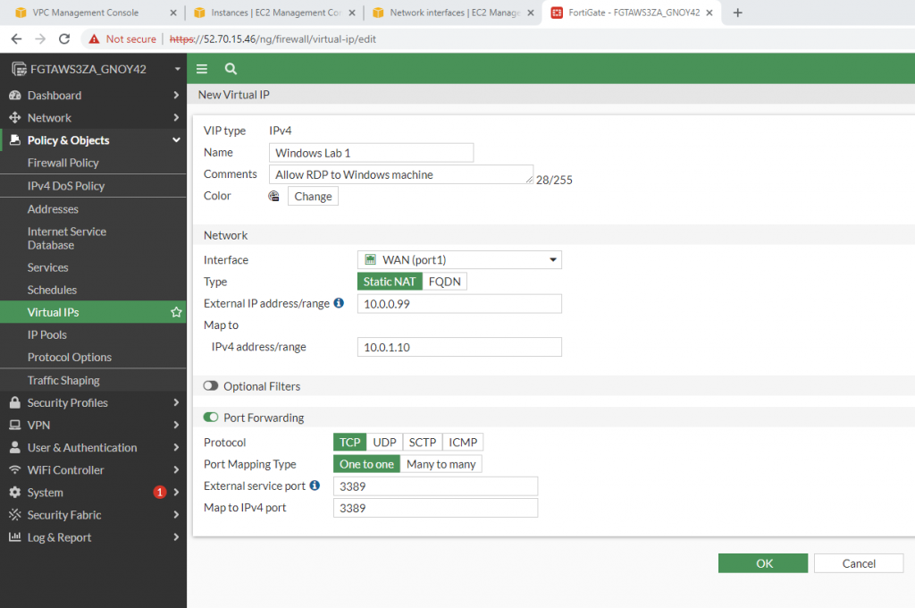
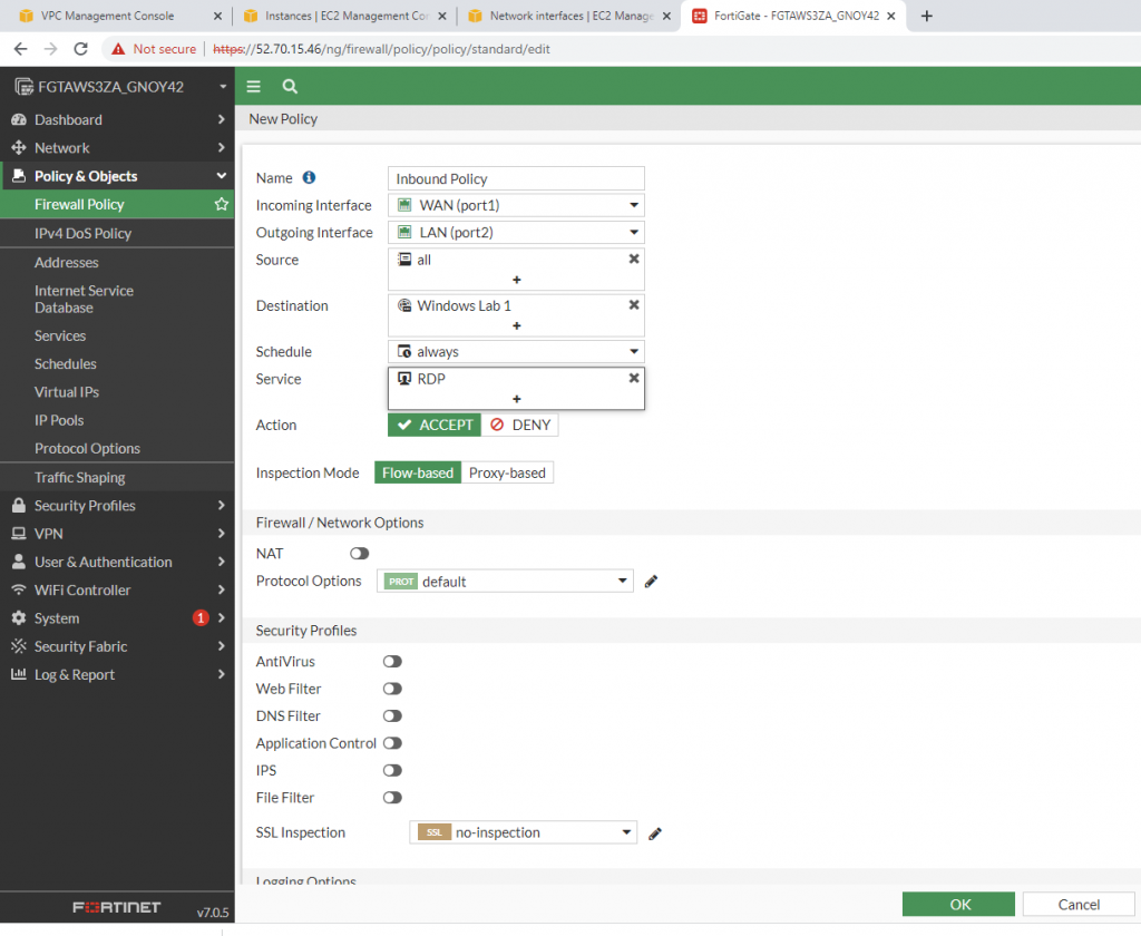
Allow inbound traffic from WAN to this machine.

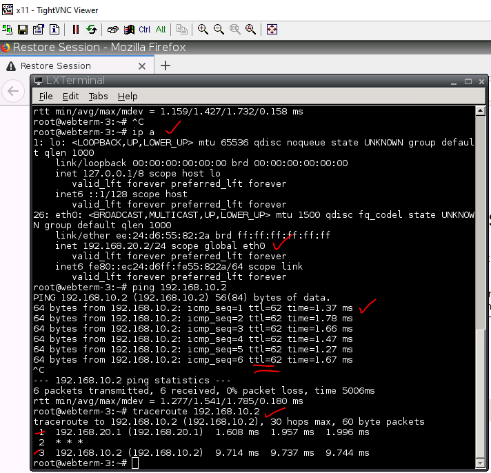
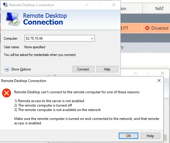
Try to access the machine.

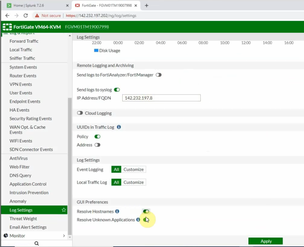
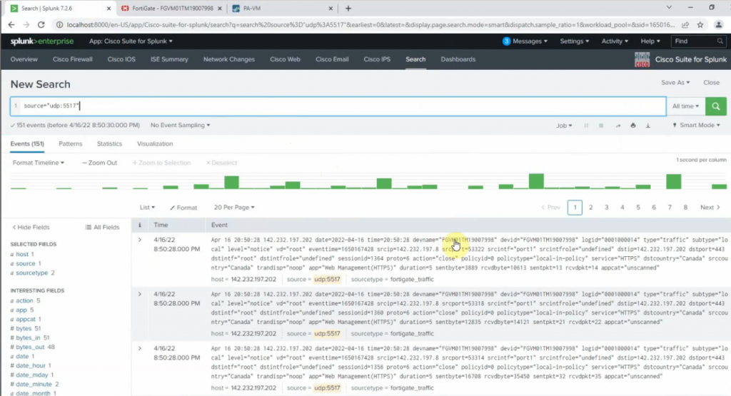
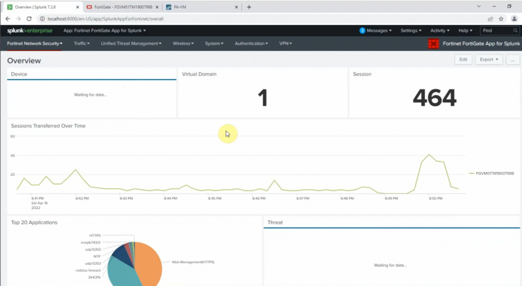
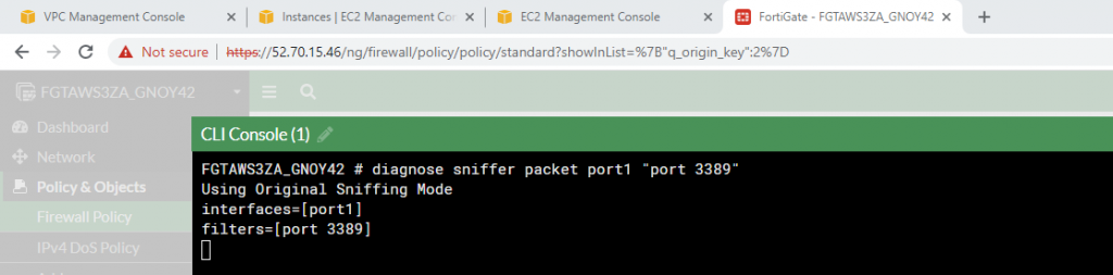
Sniffer traffic on Fortinet.

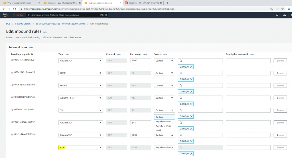
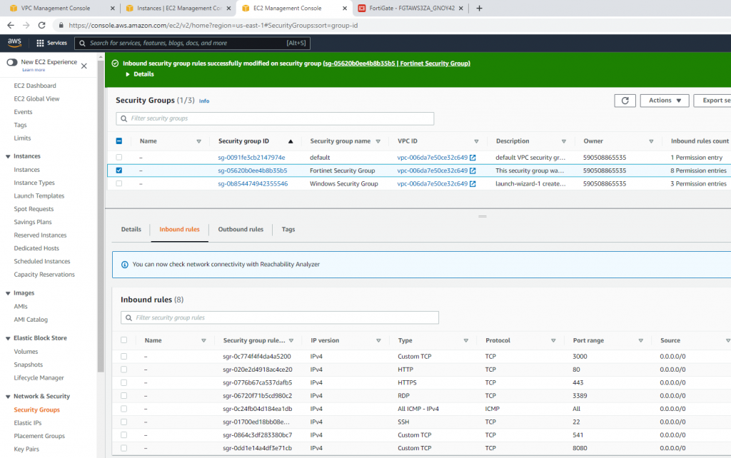
Modify the Security group to allow RDP.

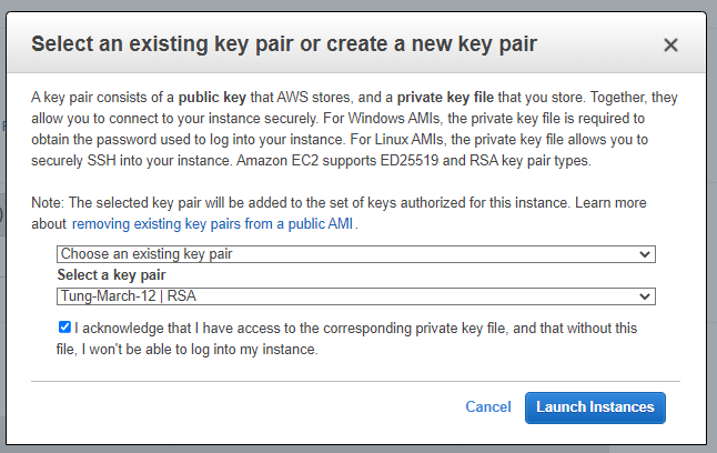
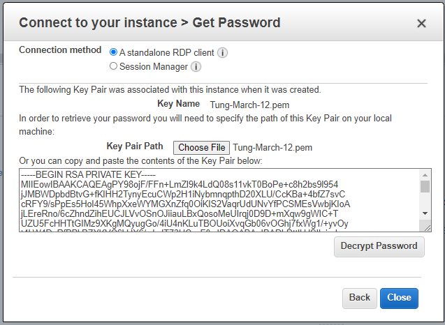
Load private key to decrypt Windows password.

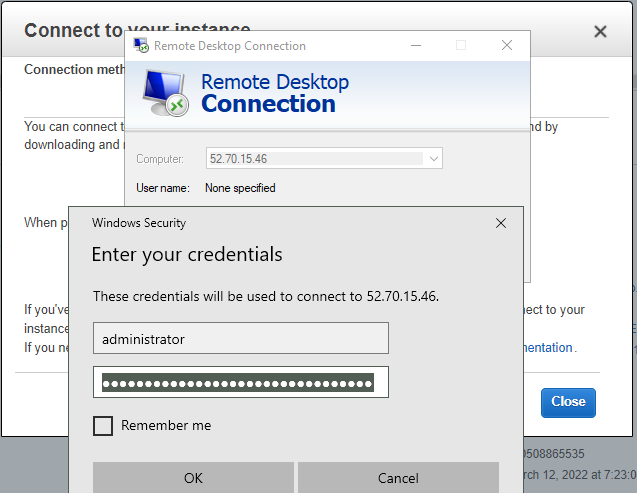
Access RDP to Windows 2016 instance on AWS.

Now we can see the RDP traffic via Fortinet.

diagnose sniffer packet port1 "port 3389"

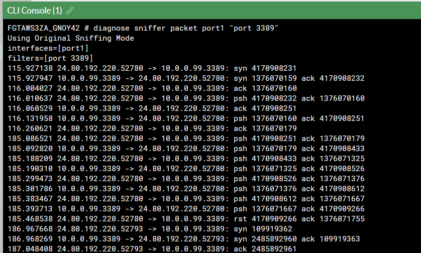
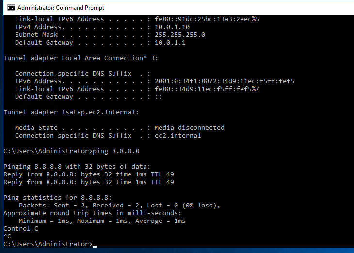
The Windows machine is able to access the Internet.

Send Palo Alto, FortiGate, Cisco Router, and Linux Server logs to Splunk

This is a diagram that I have used to deploy this lab.

Log in to Splunk, and download Cisco Suite for Splunk, Fortigate, and Palo Alto app for Splunk.

Click Install app from file.

On Splunk.

+ Palo Alto

Go to Settings – Data inputs – New Local UDP.

Enter the port 5514 on the Port setting

Source type: pan_log

App Control: Palo Alto Networks

Method: IP

Index: Default

On Palo Alto, configure to send logs to Splunk server with destination port is 5514.

Commit, log off and log on to generate logs.

Back to Splunk.

Click Palo Alto App – Operations – Real-time Event Feed.

+ Cisco Router R1.

conf t
logging trap informational
logging host 142.232.197.8 transport udp port 5515 

On Splunk.

Port 5515

Source type: cisco:asa

App Context: Cisco Suite for Splunk

Method: IP

Index: default.

Back to Router, send sample logs to Splunk.

end
send log "Tung Le"
send log "Tung Le"

+ On Kali Linux.

sudo su
nano /etc/rsyslog.conf
##Add the following line to the end of the file. The listening port is 5516.
*.*                @142.232.198.8:5516

Restart rsyslog service.

systemctl restart rsyslog
systemctl status rsyslog

Back to Splunk, configure the listening port for the Linux server is 5516

source type: Syslog

app context: Apps Browser

Back to Kali, type the command below to generate logs to Splunk.

logger "Tung Le"

+ FortiGate:

Configure FortiGate to send logs to Splunk via the UDP port 5517.

config log syslogd setting
set status enable
set server 142.232.197.8
set port 5517
end 

Log into FortiGate, and enable the setting below to send logs to Splunk.

On Splunk, configure port is 5517.

Source type: fgt_log

App Context: FortiGate

Method: IP

Index: Default

Log off FortiGate, type w wrong password to generate logs.

Create an IPSEC site-to-site tunnel between Palo Alto And FortiGate.

This is the lab to use to set up the IPSEC site-to-site tunnel between both devices.

On Palo Alto.

IKE Crypto.

IPSEC Crypto.

IKE Gateway.

IPSec tunnel.

Create a virtual route from PA to Fortinet.

Create two Security Policies to allow traffic from the “Trusted Zone” of PA to the “Trusted Zone” of Fortinet.

Configure Fortinet.

config system interface
edit port1
set mode dhcp
set allowaccess ping httpd http fgfm
next
end
show system interface 
# show system interface to get IP Address from DHCP

Go to Webterm to configure Fortinet.

Configure a custom VPN Tunnel with the following information.

Configure a static route to allow traffic from Trusted Zone (192.168.20.0/24) on Fortinet to the Trusted Zone (192.168.10.0/24) on PA.

Create two Security policies to allow traffic from VPN to Trusted Zone and vice versa.

Ping and traceroute from a VM on Fortinet to another VM on Palo Alto.

Monitor IPSEC tunnel on Fortinet.

Monitor IPSEC tunnel on PA.

Configure host-check for SSLVPN connections on FortiGate

This is a diagram to do a host-check SSLVPN connections lab.

Enable tunnel-mode SSLVPN

Enable host-check for Antivirus and Firewall enabled on Fortinet.

Windows machine is up to date and Windows Firewall is enabled.

Setup Forticlient on Windows machine.

Move to unpatched and disabled Windows firewall’s machine.

SSLVPN connection is failed.

Enabled Windows Firewall

Windows OS is not up to date.

Creating an SSLVPN connection again, it was failed.

Checking on Forticlient log and Fortinet Web management console.

Configure DoS Policy on FortiGate

This is a diagram to do a Fortinet Dos Lab.

Fortinet – Policy and Objects – IPv4 DoS Policy.

Change TCP_port_scan setting to 5 and ICMP_flood setting to 4.

Configure quarantine setting on the Fortinet DoS Policy.

config firewall DoS-policy

    edit 1

        set interface “port1”

        set srcaddr “all”

        set dstaddr “all”

        set service “ALL”

        config anomaly

            edit “icmp_flood”

                set status enable

                set log enable

                set quarantine attacker

                set quarantine-expiry 5m 

                set quarantine-log disable

                set threshold 4

            next

        config anomaly

            edit “tcp_port_scan”

                set status enable

                set log enable

                set quarantine attacker

                set quarantine-expiry 5m 

                set quarantine-log disable

                set threshold 5

            next

Sending 5 packets per second, Fortinet starts to block the excessive ICMP packets.

Check Fortinet Anomaly log.

Fortinet Fortiview.

Fortinet Monitor – Banned IP. AT IP Address was blocked by Fortinet Firewall.

Doing port scan on Kali machine by using Nmap command.

Fortinet was blocked port scan on the opened port 80.